 Hans Jørgen Grimstad
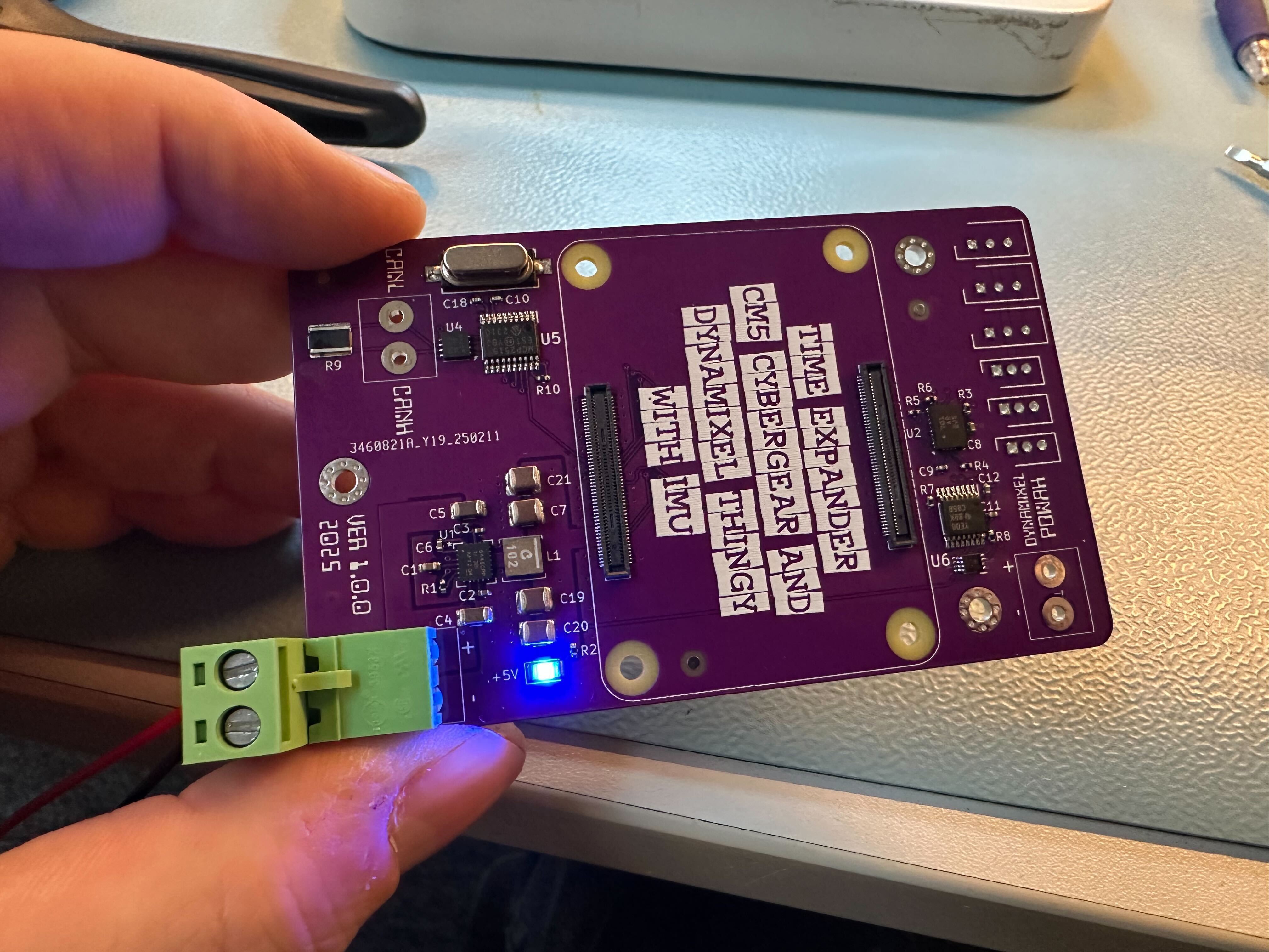
Just finished assembling two of the boards. So far, I have only tested the 5V power rail. Power LED lights up and no detectable current draw withouth the CM5 in place. This is a good sign, since there is no smoke coming out and no shorts between power and ground anywhere.
My biggest worry was the tolerances of the CM5 connectors, but the footprint / placement seems to be ok. The module snapped into place without any problems.
Next, I'll have to verify that the pinout is OK. Since I am going to use both SPI, I2C and UART + a couple of GPIO pins, it is entirely possible that I have made a mistake that will require a modification and a new revision (200 pins and mutually exlusive I/O function assignments is a recipe for future facepalms)


Discussions
Become a Hackaday.io Member
Create an account to leave a comment. Already have an account? Log In.