 kuokuo702
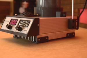
3D-Printed Version Stringing Demo
This video provides a real-world example of how the machine operates and handles stringing efficiently. If you have any questions or feedback, feel free to leave a comment!
Functions
- LB/KG display and setting
- Pre-Stretch function
- Constant-Pull system
- Knot function
- Tension adjustment manually during tensioning
- Tension calibration
- Stringing timer
- Tension timer
- Tension counter and boot counter
- Detailed recording of tensioning logs
- Pull speed with 9-speed selection
3D-Printed Parts Download
PicoBETH HW 3D Printed Version
Caution: Avoid using PLA for printing as its strength may degrade over time.
3D Viewing Model (Non-Printable)
Parts List
Main Components
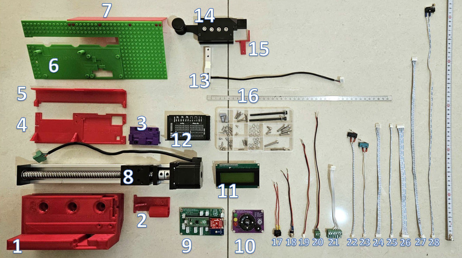
| No. | Name |
|---|---|
| 1 | Part-1 Main Body |
| 2 | Part-2 Rear Limit Mount |
| 3 | Part-3 Load Cell Bracket |
| 4 | Part-4 PCB and TB6600 Mount |
| 5 | Part-5 Power and Switch Cover |
| 6 | Part-6 LCD and Button Mount |
| 7 | Part-7 Rear Cover |
| 8 | SGX 1610 200mm Sliding Table |
| 9 | PCB Mainboard, Raspberry Pico, SparkFun HX711, Buzzer |
| 10 | PCB Button Board |
| 11 | 2004 i2c LCD |
| 12 | TB6600 Stepper Motor Driver |
| 13 | NJ5 20kg Load Cell (YZC-133) |
| 14 | WISE 2086 Clip Head |
| 15 | Activation Switch Mount |
| 16 | Ø4 20cm Wire Wrap |
| 17 | Power Switch 12cm |
| 18 | DC Jack Cable 15cm |
| 19 | Mainboard Power Cable 20cm |
| 20 | TB6600 Power Cable 28cm |
| 21 | XH2.54mm 4P Stepper Motor Signal Cable 15cm |
| 22 | XH2.54mm 2P Front Limit Switch Cable 20cm |
| 23 | XH2.54mm 2P Rear Limit Switch Cable 20cm |
| 24 | XH2.54mm 4P LED Signal Cable (Same Direction) 25cm |
| 25 | XH2.54mm 2P Cancel Button Cable (Same Direction) 25cm |
| 26 | XH2.54mm 6P Five-Way Button Cable (Same Direction) 25cm |
| 27 | XH2.54mm 4P LCD Signal Cable 40cm |
| 28 | XH2.54mm 2P Clip Activation Switch Cable 50cm |
Warning: Power cables must not be thinner than 22 AWG.
Screw List
| No. | Name | Quantity |
|---|---|---|
| A | Gray Spring Wire Connectors | 3 |
| B | M3 × 10mm Self-Tapping Screws | 8 |
| C | M3 × 6mm Self-Tapping Screws | 15 |
| D | M2.6 × 10mm Self-Tapping Screws | 4 |
| E | M3 × 6mm Round-Head Screws | 2 |
| F | M4 × 16mm Hex Screws | 4 |
| G | M4 × 20mm Hex Screws | 4 |
| H | M4 × 30mm Hex Screws | 2 |
| I | M4 × 8mm Hex Screws | 2 |
| J | M4 Spring Washers | 10 |
| K | M4 Flat Washers | 10 |
| L | M5 × 80mm Hex Screws + Washers | 2 |
Assembly Steps
Follow the YouTube Tutorial Video for detailed assembly instructions.
Step 1: 3D-Printed Parts
Main Body (PART-1)
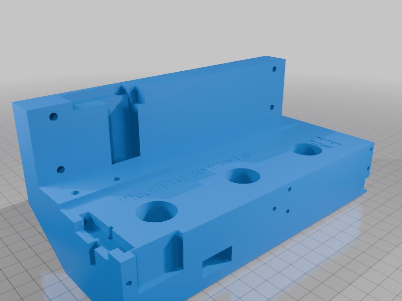
- The main body must withstand significant deformation forces. Recommended print settings:
- Wall Thickness: At least 5mm
- Infill: At least 30%

Load Cell Bracket (PART-3)
This part serves as the mounting bracket for the Load Cell and the sliding table. Recommended print settings:
- Infill: 100%
Step 2: Assembling the Main Body (Part-1)
- Attach the bottom of the main body to the sliding table using M4 x 30mm screws + spring washers + flat washers x2 (keep them slightly loose for adjustment).
- Attach the sides of the main body to the sliding table using M4 x 20mm screws + spring washers + flat washers x4 (keep them slightly loose for adjustment).
- Align the main body with the sliding table.
- Tighten the bottom M4 x 30mm screws x2 to a torque of 1.5 Nm.
- Tighten the side M4 x 20mm screws x4 to a torque of 1.5 Nm.
Caution: Ensure washers are installed, and tighten screws to the recommended torque to prevent damage to the 3D-printed parts.
Step 3: Assembling the PCB and TB6600 Mount (Part-4)
- Secure the TB6600 to the mount using M3 x 10mm self-tapping screws x4.
- Secure the PCB using M3 x 10mm self-tapping screws x2 and M3 x 6mm self-tapping screws x2.
- Connect the TB6600 power cables, control signal cables, and motor signal cables.
- Secure the TB6600 mount to the frame using M3 x 10mm self-tapping screws x2.
Step 4: Wiring the Power Cables
- Install the power switch and DC jack onto the Power Cover (Part-5).
- Insert the mainboard power cable into the mainboard.
- Use gray spring wire connectors to connect the DC jack positive wire to...
 BoboPL
 Becky Stern
 Greg Zumwalt
 Micahel Guerero