 Konstantin D.
This project was inspired by the book of Sten Odenwald 'Exploring Space Weather with DIY Magnetometers'.
The book presents several simple DIY ways of registering the changes in geomagnetic field.
Among them there is a chapter describing how to use a sensitive magnetometer board RM3100 connected to Arduino UNO micro-controller. Magnetometer was developed by PNI Sensor Corporation; there is a detailed guide from PNI for interfacing this sensor with Arduino platform; the guide is available at https://github.com/hnguy169/RM3100-Arduino/tree/main
For the reference, here is RM3100 specification from PNI:
https://www.tri-m.com/products/pni/RM3100-User-Manual.pdf
Arduino-based construction described in the book is very basic; so I decided to try this sensor board myself having in mind to produce somewhat more elaborated design; when working on this small project I had a lot of fun and also learned some new tricks. So I think it might be worth sharing my experience with the community of fellow makers and also to express a gratitude to Sten Odenwald for sharing with us such an inspirational piece of his own knowledge and experience.
So below are the main features of my implementation of Arduino-based magnetometer:
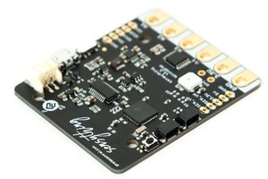
1. ESP32 board as a main controller(MCU). It allows to overcome RAM restrictions of most Arduino boards; it is also capable of connecting to Internet with WiFi.
2. Magnetometer RM3100 communicates with MCU through SPI interface
3. SD-card board is attached to MCU (SPI interface as well) and every minute averaged magnetometer reading alone with exact timestamp is stored on micro-SD card in .csv file. Upon every power-on MCU creates automatically a new file on SD with unique name.
SD card can be extracted during the working cycle without stopping the measurements; if SD card is re-inserted, a new file with timestamp is created on the card and data is placed into the new file;
4. There is a simple two-color LED indicator of MCU functioning: permanent red while connecting to WiFi router/modem, blinking red if SD card is missing, blinking green when data processing is normal.
5. MCU reads magnetometer data based on the state of 'data ready' pin of RM3100; magnetometer "cycle counts" parameter is set to 400. (I found that setting this parameter to 800 does not increase sensitivity but greatly increase the noise level. )
MCU reads 3 components of magnetic field and calculates the total value as
After that it calculates moving average value Bavg
6. There is a high precision RTC (real time clock) board attached to MCU via I2C interface. RTC uses DS3231 chip with temperature compensation. RTC board provides a timestamp for creating a data file on SD and also for each magnetometer measurement; it also generates an alert (changes the status of designated pin) every 60 seconds; when this alert occurs the current value of Bavg is recorded on SD along with current timestamp.
7. Besides recording data on SD card, the measurements are also sent to the internet to IoT platform ThingSpeak.com.
WiFI connection credentials and ThingSpeak channel API write key are stored on SD and can be easily adjusted;
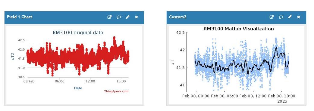
Using this data MCU connects to my local cable modem/router (Comcast) through WiFi; after connection with network is established it sends every minute a http request with Bavg value to api.thingspeak.com to my free account. This account has a public channel where the data is visualized as a time series plot. ThingSpeak.com provides only basic visualization, but it also offers to utilize Matlab Visualization application for more sophisticated processing of incoming data.
So I made a simple template-based program for Matlab app: it implements Savitzky–Golay filtering of incoming data and displays the result as a smooth curve superimposed over the original data points.
Here is an example of ThingSpeak visualization of magnetometer data:
I also decided to insure...
Read more »
 Ashwin K Whitchurch
 Makerfabs
 electronicsworkshops