Close
0%
0%

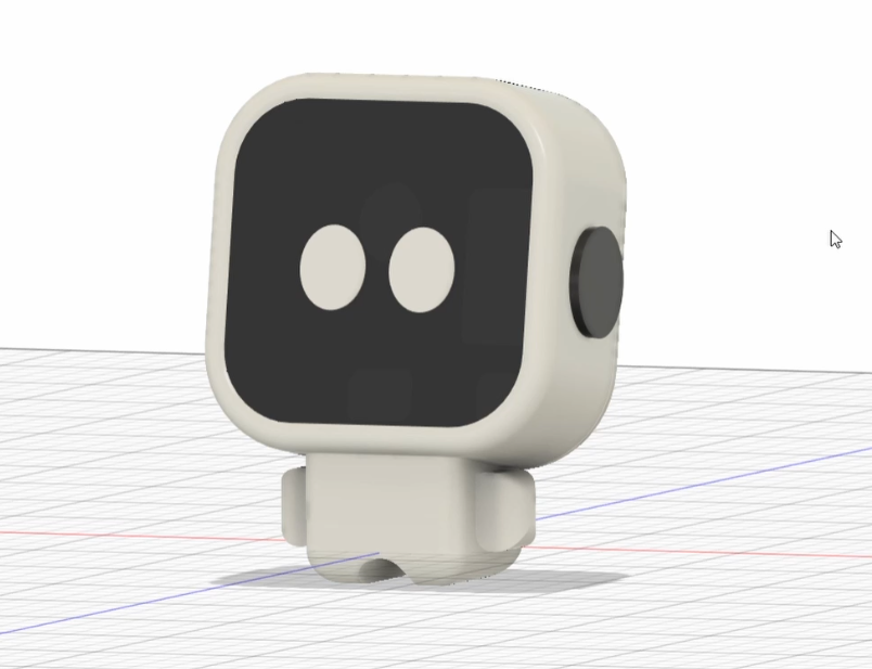
A robot that uses emotions to indicate room health

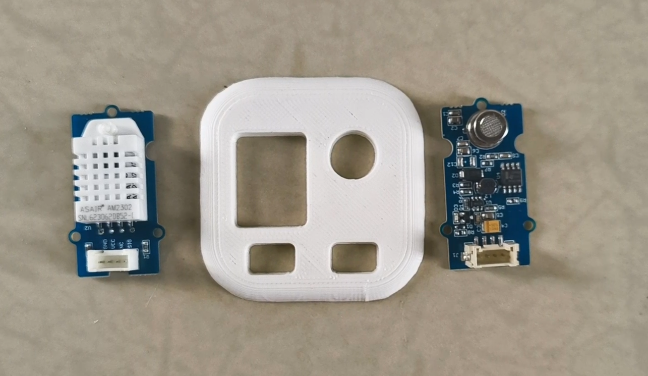
This is version 2 of my previous project - Gus. This little guy uses eye emotions to show how good (or bad) your room health is.

Similar projects worth following
Gus is basically your adorable desktop buddy with these super expressive eyes. He even blinks randomly, just to make him feel more alive. Behind his head are a bunch of sensors that keep tabs on the temperature, humidity, and air quality around him.

And here's the cool part: his eye levels actually tell you how comfy your room is. So, if the air quality's not great, or the humidity's off, or the temperature's just not right, his eyelids start to droop, and he gets a little gloomy.

And there's a hidden touch sensor on top of his head. Whenever you're wondering why he's feeling down, just give him a little tap, and he'll show you exactly what the sensors are reading. That way, you'll know if you need to crack a window, turn on the fan, or whatever it takes to get him feeling fresh again.

Check out the full instructions on youtube.

Gus_2_0.ino

Main arduino code

ino - 6.52 kB - 02/20/2025 at 13:16

Download

head_back.stl

Standard Tesselated Geometry - 186.02 kB - 02/13/2025 at 04:25

Download

head.stl

Standard Tesselated Geometry - 339.54 kB - 02/13/2025 at 04:25

Download

legs.stl

Standard Tesselated Geometry - 85.43 kB - 02/13/2025 at 04:25

Download

body.stl

Standard Tesselated Geometry - 24.30 kB - 02/13/2025 at 04:25

Download

View all 8 files

  • 1 × xiao esp32c3
  • 1 × grove oled display 1.12"
  • 1 × DHT22 sensor
  • 1 × Grove air quality sensor
  • 1 × jumper wires / grove connectors

  • 1
    Design the CAD models

    So the first step in bringing Gus to life was getting his body designed in Fusion 360.

    Now, before diving into the details, I wanted to get a feel for his overall size. So, I started sketching out some really rough shapes of all the electronic components that will be going inside him. 

    To make absolutely sure everything would fit perfectly, I did a little online scavenging and downloaded CAD models of all the electronics from Grabcad.


    My idea for Gus was a big head to house the larger components and a cute little body for the microcontroller. And you know what? This look actually turned out to be very cute!

    I carefully positioned all those digital components within Gus's body, to make sure everything fit in perfectly. Unfortunately, I couldn’t find a CAD model for the air quality sensor, so I had to take my best guess at its size.

    To add to the final look, I made some tiny hands and feet.


    Finally, I exported the whole design and sent it off to be 3D printed. And honestly, for my very first time designing something specifically for 3D printing, it looks pretty good. 

  • 2
    A little fix

    The first thing I noticed after 3D printing was the air quality and temperature sensors weren't quite fitting into their designated slots.

    Well, looks like my first design wasn’t perfect after all.

     But thankfully, it was a pretty straightforward fix. I just used a hacksaw blade to carefully remove the lower sections of the slots, specifically below where the Grove connectors would go.

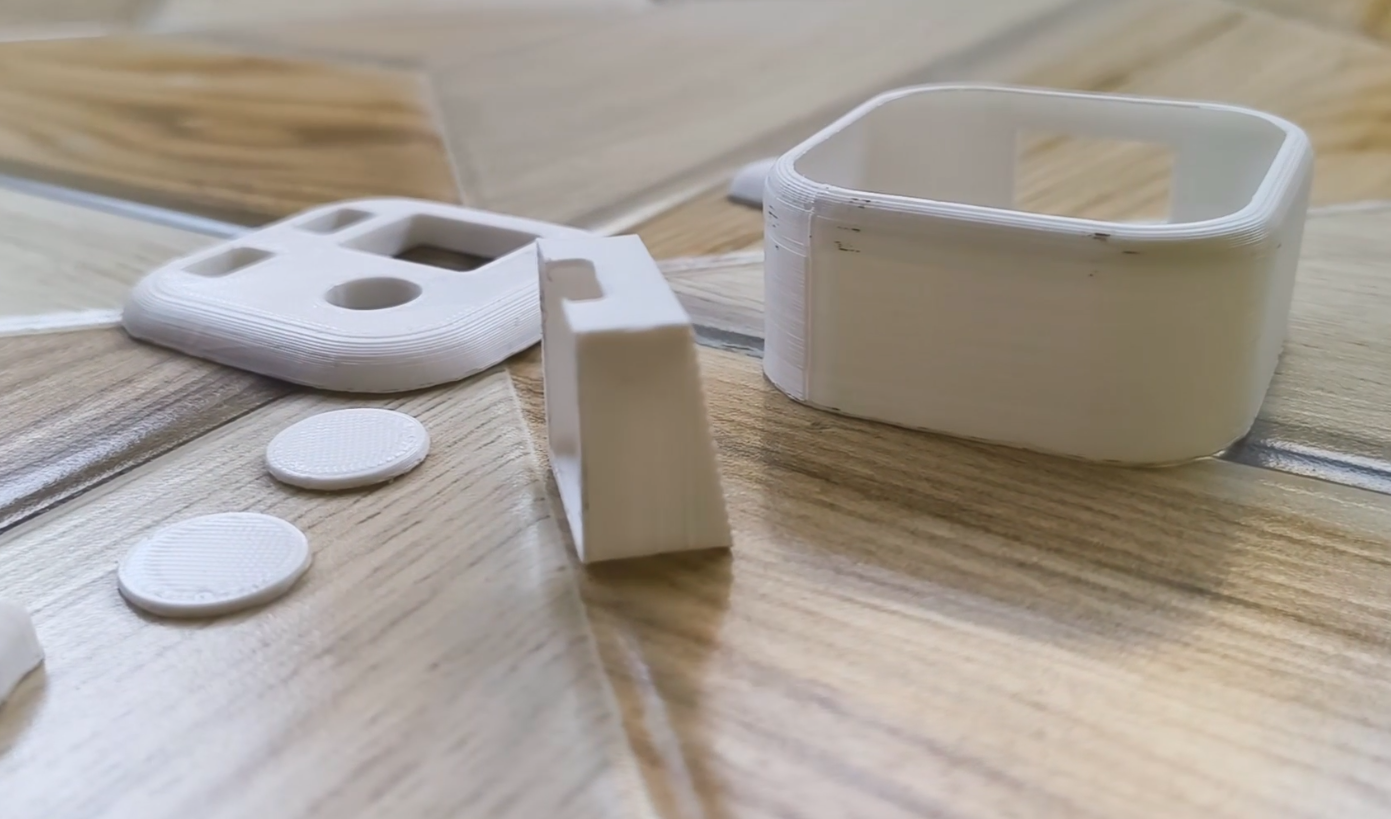
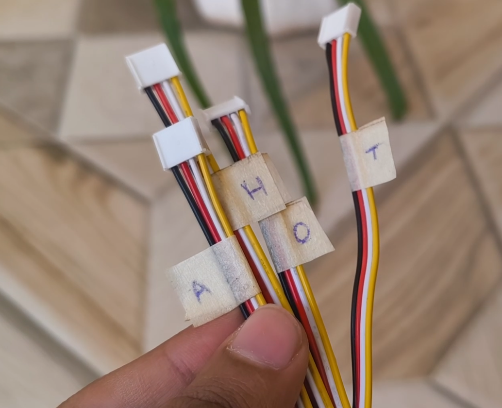
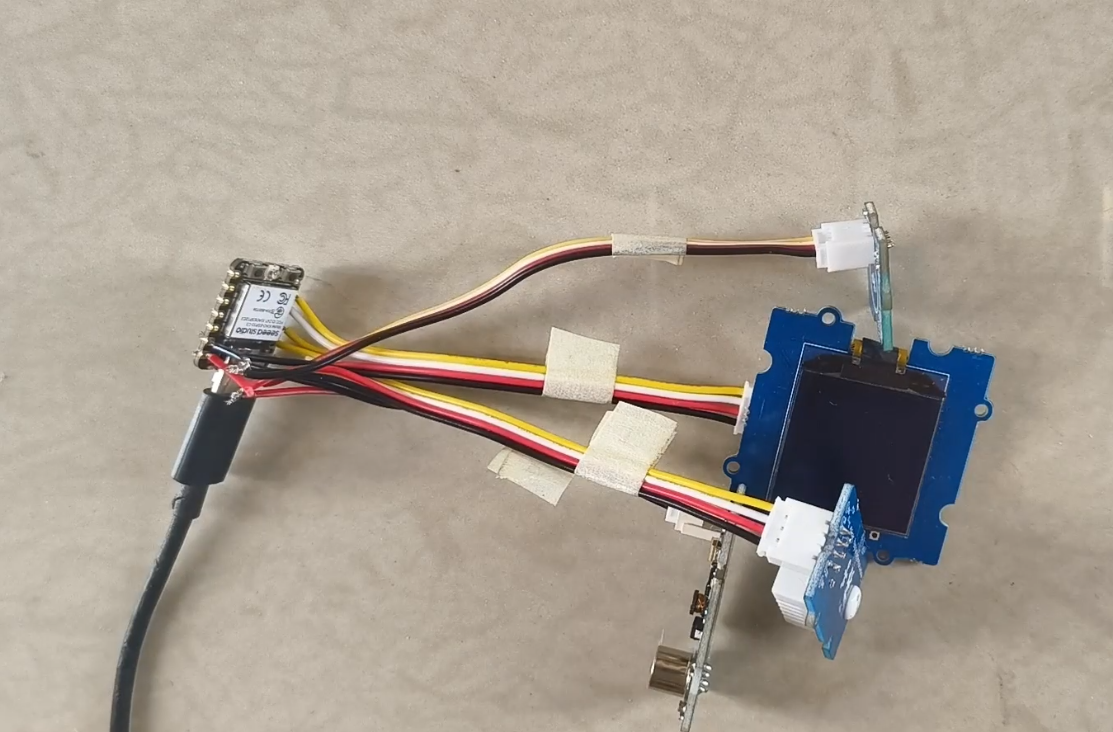
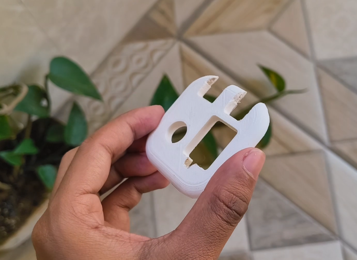
    This also created some extra space for the sensor wires to bend back inside the housing.
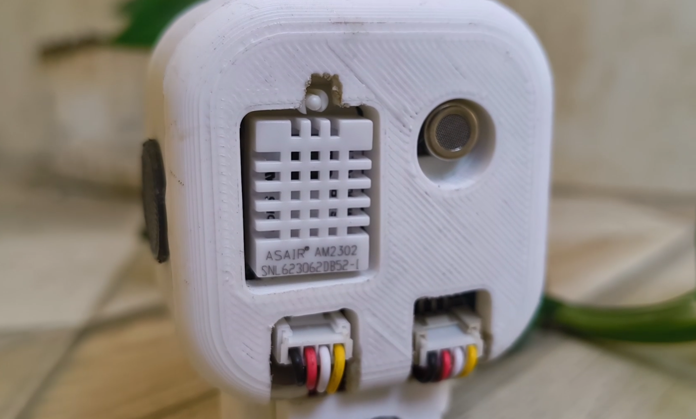
    Thinking about it, it might actually be more convenient if Seeed Studio had placed the Grove connectors on the opposite side of the PCB. That seems to make more sense.

  • 3
    Solder wires

    Alright, let's get started with the soldering! First, I'm going to cut two of the grove connectors roughly in half. Then, using wire strippers, we'll expose the ends of all these wires.


    For three of these connectors, we're going to snip off the white wire – it won't be required by our sensors. But for the last connector, the one for our OLED display, we need all four wires because it uses the I2C communication protocol.


    Now, I know it looks like a lot of wires, but don't worry! We'll take it step by step. Let's start by soldering bare red and black wires to the VUSB and GND pins on the microcontroller.  

    Next, we'll grab the yellow wires from those three connectors where we removed the white wire, and solder them to D0, D1, and D2.

    Then, for the OLED connector, we'll solder its white wire to D4 and its yellow wire to D5. Finally, we're going to connect all the red wires together and all the black wires together.  

    If you're feeling a bit lost, take a look at this circuit diagram while soldering.


    To keep everything organized, I've labeled each connector with masking tape, indicating what component it will connect to later. Here's a reference diagram for you to do the same.  

    The good news is we don’t need to do any more soldering. We can simply plug in our components using the connectors, just matching them up with the labels.

View all 10 instructions

Enjoy this project?

Share

Discussions

Similar Projects

Does this project spark your interest?

Become a member to follow this project and never miss any updates