 Tony Francis
Last time we shared a 500–1000 nm spectrometer design that landed around 3–4 nm resolution. Decent, but not great — best was 2.1 nm at 600 nm, worst stretched to 4.2 nm. We suspected the camera was holding us back. Turns out we were right, and the fix came from a lens that’s curved in only one direction. With it, the design now sits at ~1.9 nm across the band, confirmed in BeamFour. And as always, it’s open‑source
Where we left off
Our earlier log traced a cost-optimised 500–1000 nm spectrometer built from stock 1‑inch lenses. It worked, but the resolution sat around 3–4 nm and the spots got fat toward the edges of the band. We said at the time that the limit wasn't the colours and wasn't diffraction — it was something about the camera. This log is what that "something" turned out to be, and how we fixed it.
Everything here is done in BeamFour, a free ray tracer, plus a few Python scripts. No expensive optics software.
The problem: the camera focuses onto a bowl, not a flat plane
When we looked carefully, every wavelength was actually sharp — at its own best focus. The catch is that "best focus" isn't at the same distance for every colour. It swings back and forth by about 2 mm across the band, in a smooth curve. The camera's focal surface is a shallow bowl, and our detector is flat, so only part of the spectrum can ever be in focus at once. The band edges (500 and 1000 nm) sit deepest in the bowl, which is exactly where the spots were worst.
This is called field curvature, and it's a property of a simple lens — not colour, not diffraction. Tilting the detector helps a little (it lines up with the average slope), but you can't tilt a flat plane to match a curved bowl.
The fix: a lens curved in only one direction
Here's the key insight. In a spectrometer, only one axis matters for resolution — the direction the colours spread out in (the "dispersion axis"). Blur in the other direction (along the slit height) just smears the line vertically; it doesn't mix one wavelength into the next.
So instead of a normal (spherical) corrector lens, we used a cylindrical one — a lens curved in the dispersion plane and flat in the other. It flattens the focal bowl exactly where it counts, and leaves the slit-height axis alone. A normal spherical corrector would also stretch the whole spectrum (it acts like a Barlow) and we'd run off the end of the sensor; the cylinder sidesteps that because it only has power in the one plane.
It's a plano-cylindrical piece of N‑BK7, sitting just in front of the detector.
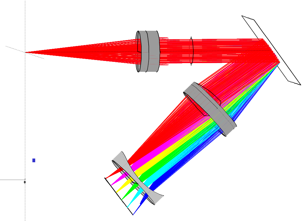
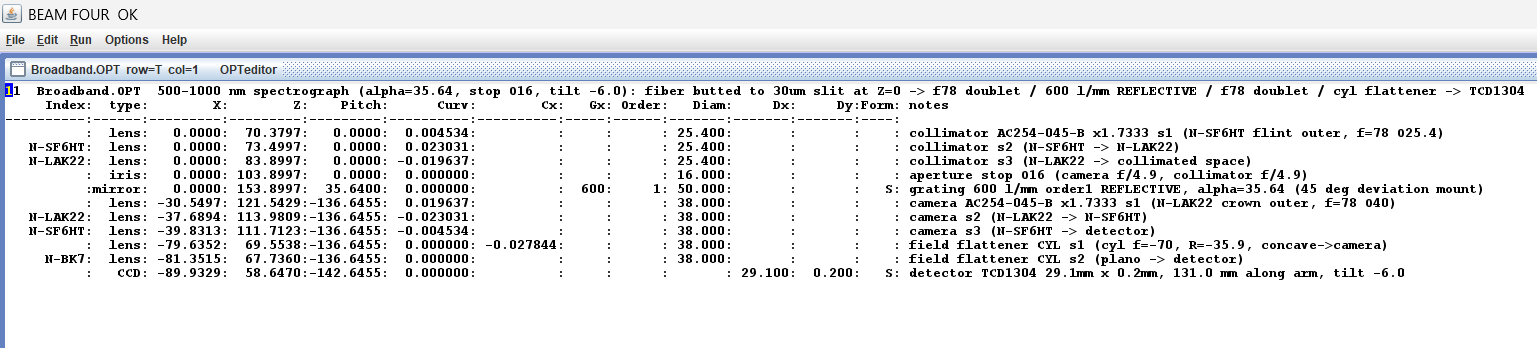
Figure 1: The full trace. Fiber (far left) → collimator → grating → camera → the cylindrical field flattener (the small concave lens before the detector) → TCD1304. The rainbow is the 500–1000 nm spectrum being sorted onto the sensor.
The result: ~1.9 nm
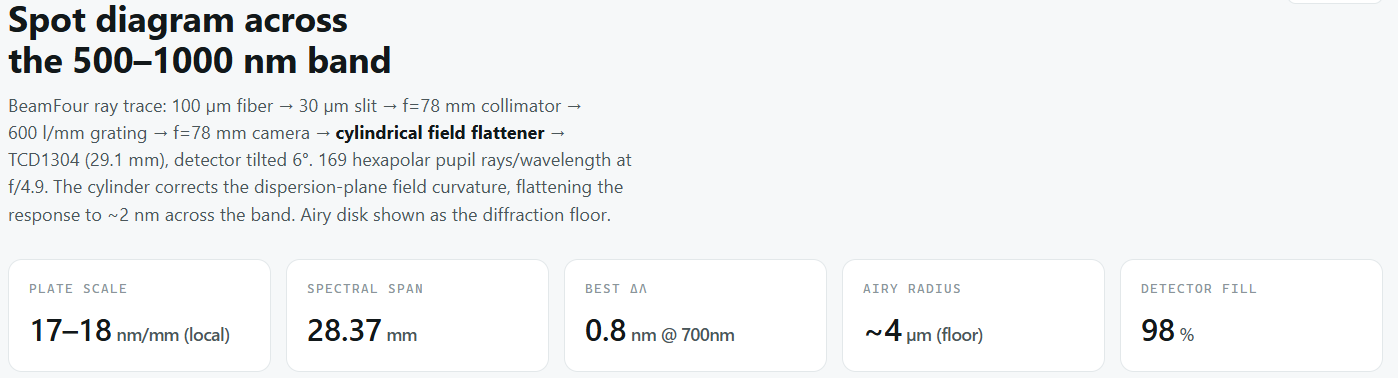
With the cylinder in and the detector refocused, the delivered resolution across 500–1000 nm is:
- ~1.9 nm mean, 2.9 nm worst (single exposure)
- every wavelength between about 0.8 and 2.9 nm — no bad outlier
That's roughly a 40% improvement on where we were. And this number isn't just from our own script: we encoded the cylinder in BeamFour's own format and traced it there. Our offline tracer and BeamFour agree to better than a tenth of a micron on every wavelength, so the physics is trustworthy.
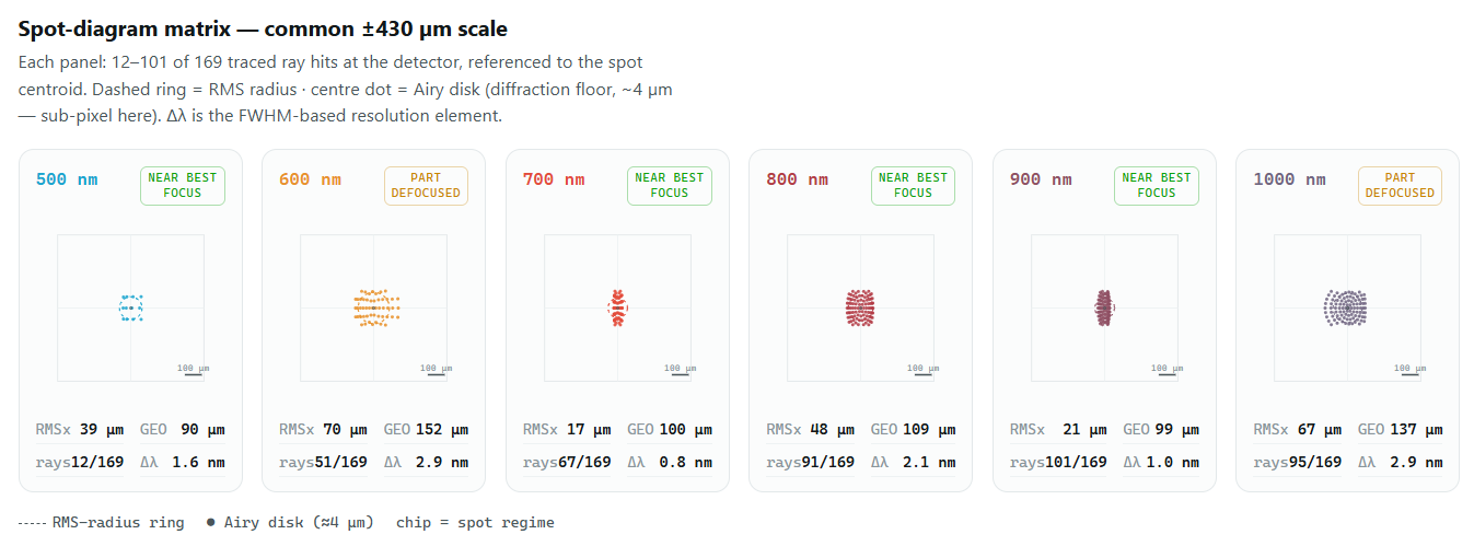
Figure 2:The spot analysis from the BeamFour trace. Each panel is one wavelength; the numbers are the RMS spot size and the delivered resolution Δλ
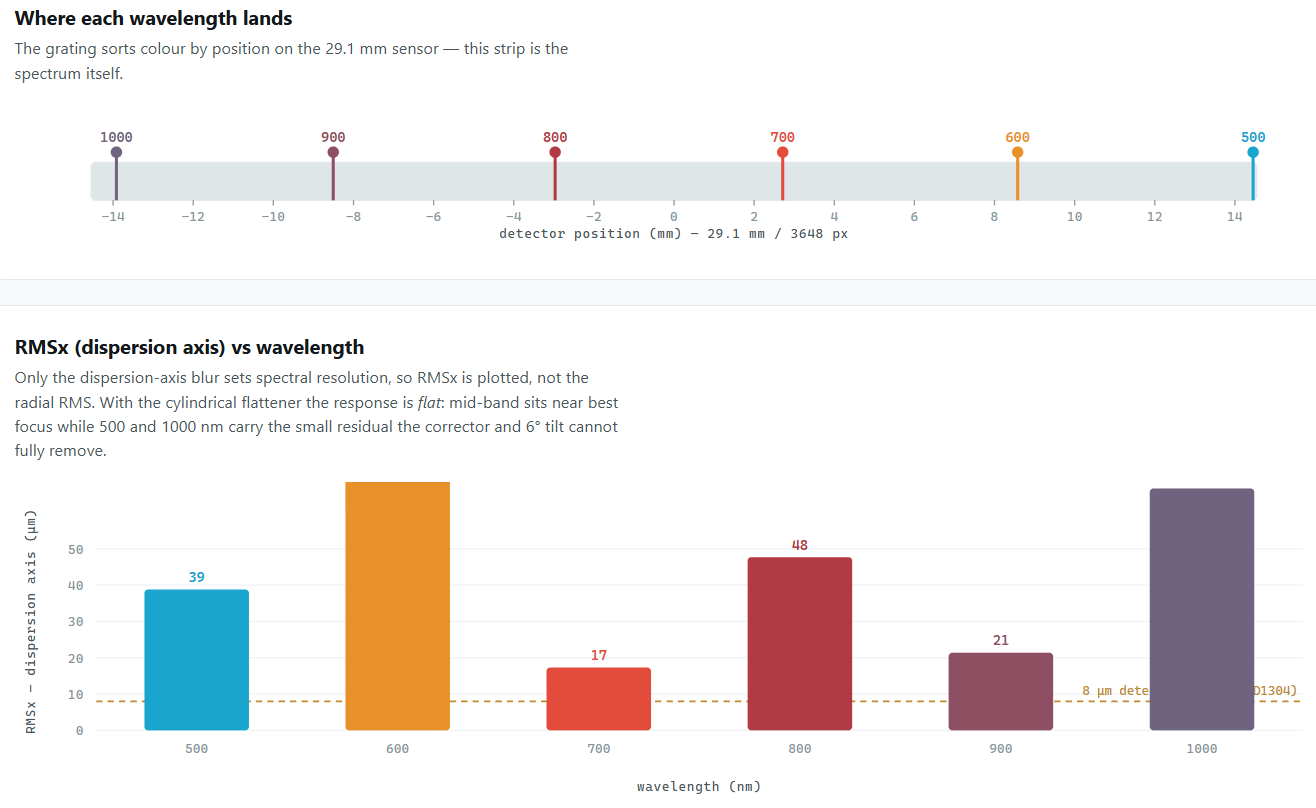
Figure 3: RMSx (spectral-axis blur) for each wavelength. The dashed line is one detector pixel.
Two Points worth noting
We removed the fiber relay entirely. The old design imaged the fiber onto the slit through a pair of lenses; a commenter on our last post rightly pointed out that (a) those relay aberrations don't actually belong in the spectrometer's resolution budget, and (b) for a fiber instrument you can just butt the fiber right up to the slit. That's what we do now — the fiber sits at the slit plane, a 100 µm fiber overfilling a 30 µm slit, which also keeps the wavelength calibration stable if the alignment drifts. Fewer parts, cleaner model.
And the flattener is a custom part — like our scaled f/78 doublet, it's not a catalogue item, so it has to be made.
What it would take to reach 1 nm
For anyone curious how much further this could go: each wavelength is already ~0.5 nm at its own best focus, so the optics themselves aren't the wall — the single flat detector is. The remaining error is the small chromatic part of the focal curve that one cylinder can't fully remove. Closing that to a genuine single-shot ~1 nm would take a field-corrected, multi-element camera (a Petzval-type group with enough degrees of freedom for the full field), which is a real optical-design job rather than a part swap. We haven't taken that on — the ~1.9 nm above is the design we're actually putting forward.
It's all open
Design files, the Python scripts, and a step-by-step to reproduce the exact 1.9 nm result in BeamFour are on our GitHub. Everything lives in one folder, python frontend_gen.py with no arguments regenerates the design, and there's a reference trace to check yours against. Code is MIT; the optical design is CERN‑OHL‑S.
https://github.com/CheckAG/JASPER_VIS_NIR_Optics_Design
If you know optics better than we do — and plenty of you do — we'd genuinely like the design poked at. Issues and "have you tried…" very welcome.
Discussions
Become a Hackaday.io Member
Create an account to leave a comment. Already have an account? Log In.