 Tony Francis
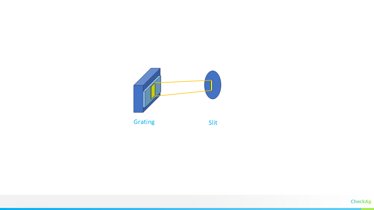
When designing a spectrometer, every photon counts! You can buy the fanciest grating in the world, but if your collimator mirror or lens is shining light past it, you're throwing away precious signal.
The key to a high-efficiency spectrometer is ensuring your grating is wide enough to capture the entire cone of light emitted from your input slit or fiber. This isn't just the beam diameter—it's the beam diameter plus a correction for the angle at which the light hits the grating.
Here’s the step-by-step derivation to find the absolute minimum physical width required for your diffraction grating Wgrating
Step 1: Defining the Light Cone and the Collimated Beam
The light exiting your input source (fiber or slit) spreads out in a cone defined by its Numerical Aperture (NA).
- Numerical Aperture (NA): This value is usually provided for optical fibers. If you have a slit and a lens, you calculate the NA from the lens-slit geometry.
Where θNA is the half-angle of the light cone.
- Collimator Focal Length (Lc): The light cone hits the collimator mirror or lens at a distance Lc. The collimator converts this diverging light cone into a parallel beam.
The maximum radius (R) of the light cone at the collimator mirror, and thus the radius of the resulting parallel beam, is found using basic trigonometry:
The total beam diameter (Dbeam) is simply twice the radius:
Step 2: The Grating Tilt—Why Wgrating > Dbeam
If your grating were positioned perfectly perpendicular to the incoming beam (α= 0°), then your required grating width (Wgrating) would simply equal the beam diameter (Dbeam).
However, in virtually every spectrometer design (like Czerny-Turner or Littrow), the grating is tilted by the angle of incidence, α.
Because the grating is tilted, the parallel beam's cross-section is stretched when projected onto the grating's surface. Think of a spotlight hitting a wall at an angle—the illuminated area is larger than the spotlight head.
The relationship between the true beam diameter (measured perpendicular to the light path) and the required physical width of the grating (measured along its surface) is given by:
Rearranging this, we find the Cos(α) Correction Factor:
Step 3: The Final, Practical Grating Width Formula
We now substitute the expression for Dbeam from Step 1 into the equation from Step 2 to get the complete, actionable formula for the minimum required grating width:
Since the half-angle θNA is defined by the Numerical Aperture,
the final formula is:
Practical Implications for Design
- NA is a Killer: If your fiber has a high NA (e.g., 0.22), the
term grows quickly, requiring a much wider grating or a much longer focal length Lc.
- Angle of Incidence Matters: The higher your angle of incidence (α) is (e.g., 60° for high dispersion), the smaller cos(α) becomes, meaning Wgrating gets much larger. This is why high-dispersion designs often require the largest and most expensive gratings!
Use this formula early in your design process to balance cost, size Lc, and efficiency.
Discussions
Become a Hackaday.io Member
Create an account to leave a comment. Already have an account? Log In.