 Tony Francis
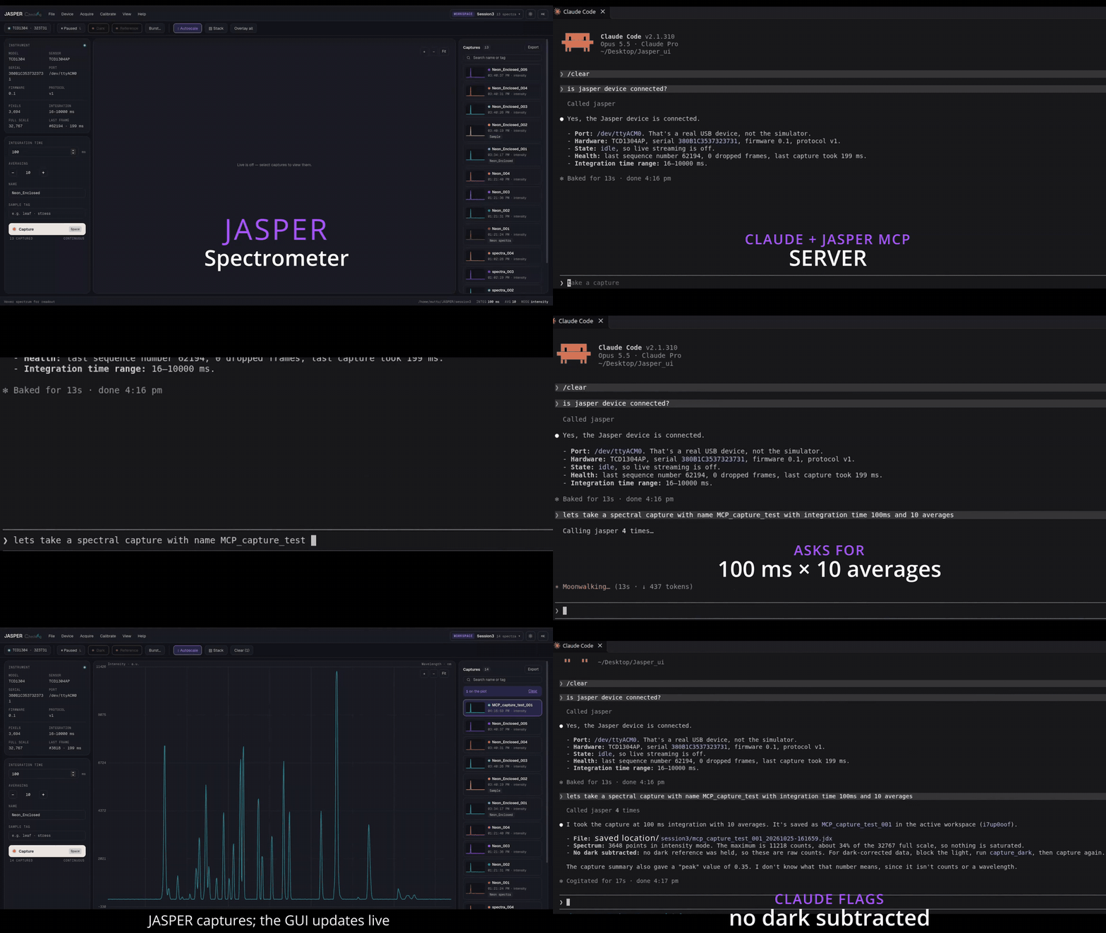
This week we connected JASPER VIS-NIR Spectrometer to Claude through an MCP server. The video is a run on the bench:
- Claude queries the device: real USB unit (/dev/ttyACM0), TCD1304AP
- firmware 0.1, protocol v1, integration range 16-10000 ms
- We ask for a capture at 100 ms integration with 10 averages
- JASPER captures, and the GUI updates live, because the GUI and the MCP server talk to the same device service
- Claude reports the result (peak about 34% of the 32,767 full scale, so nothing saturated) and flags, unprompted, that no dark was subtracted
The hardware is a work in progress: optics in the enclosure, electronics on a Renesas RA2A1 evaluation board on the bench. Optical optimisation is ongoing, so the x axis is still in pixels; wavelength calibration against Ne/Ar lines comes next.
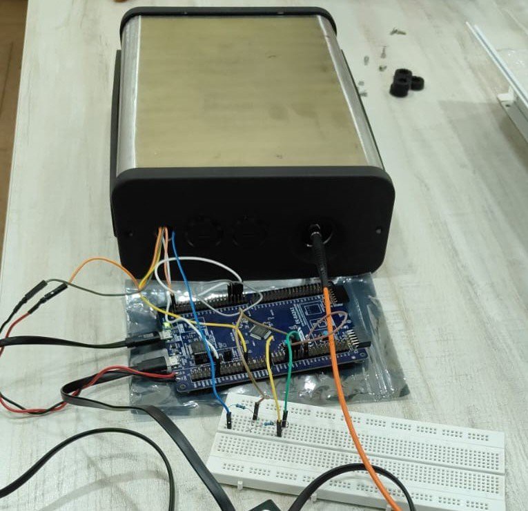
Why the RA2A1
The RA2A1 is a microcontroller with an unusually complete analog section. One chip gives us the sensor timing, the conversion and the USB link, with no external ADC or USB bridge:
| RA2A1 block | Role in JASPER | Status |
| 16-bit SAR ADC, about 1 MSPS | Digitises the TCD1304 output, one conversion per pixel | In use |
| Timers with PWM | Generate the sensor drive signals: master clock, SH (integration) and ICG (transfer) | In use |
| USB full-speed | Streams frames to the PC as a CDC-ACM serial device | In use |
| 12-bit DAC | Sets the offset (pedestal) reference in the signal chain | In use, and kept in the next revision |
| Three op-amps | Available on chip | In next version, the amplifier sits on the sensor board instead |
Signal chain today
TCD1304 output (OS) -> transistor (PNP emitter-follower) buffer on the sensor board -> RA2A1 16-bit SAR ADC, single-ended, with the on-chip DAC setting the offset reference -> ping-pong buffers in SRAM -> USB CDC-ACM -> PC.
This works, with two limits we want to remove:
- No gain stage, so the signal uses only part of the ADC range even in bright light.
- The transistor's base-emitter voltage drifts with temperature (about -2 mV/°C), which shows up as a slow baseline drift.
Next: two boards
- Sensor board: the TCD1304 with an external amplifier right next to it. Keeping the CCD's output path short and amplifying before the signal leaves the board protects it from noise picked up on the cable.
- MCU board: the RA2A1, generating the sensor clocks, setting the offset reference with its DAC, digitising the amplified signal and sending frames over USB.
Splitting the boards also means the sensor board can change (TCD1304 or Hamamatsu) without touching the MCU board.
Software side
Firmware frames go to a device service on the PC. The GUI, Python scripts and the MCP server all go through that one service, so they share live state. The firmware reports its limits (integration time 16-10000 ms), and the plan is for the service to enforce them for every caller, including Claude.
We are designing this against Anthropic's Model Hardware Standard (modelhardwarestandard.com), where each device publishes what it measures, what can be changed and its safety limits, and the driver enforces them.
What we're building next :
- Method card: analyte, matrix and range checked against the instrument
- Live coverage meter against the sample plan
- Instrument health: dark drift, I-0 age, lamp, temperature, saturation
- Every spectrum stamped with its settings and events
- Outlier ledger: every exclusion with a reason and who decided
- Rolling PCA with T2 and Q during collection, not after
- Approval steps for calibration and firmware changes
Known issues
- x axis in pixels until the Ne/Ar wavelength calibration is done
- Optics is still getting fine tuned
- One field in the capture summary ("peak") wasn't described in the MCP tool, and Claude said so. We're documenting it.
Discussions
Become a Hackaday.io Member
Create an account to leave a comment. Already have an account? Log In.