Tony Francis
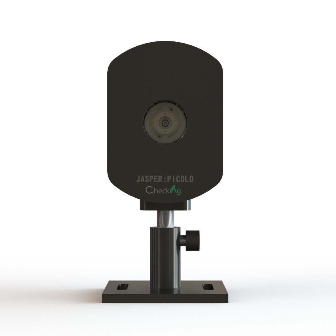
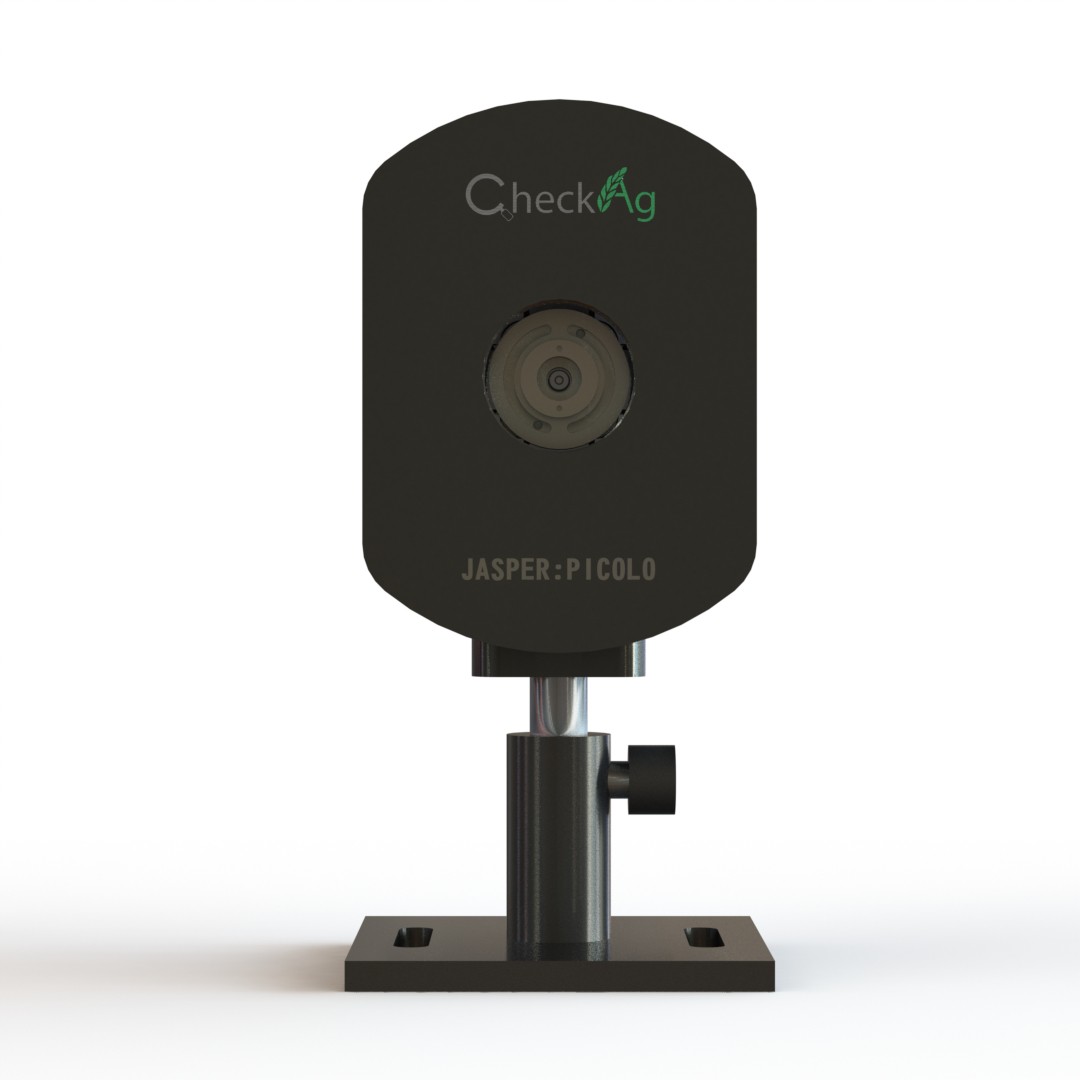
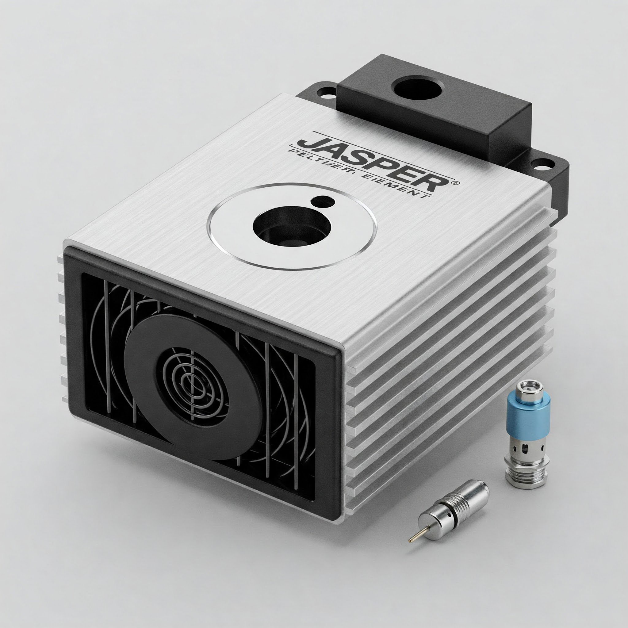
Unveiling the Jasper Picolo: A closer look at our Precision Integrated Cooling for Optoelectronics and Laser Operations (PICOLO) mount.
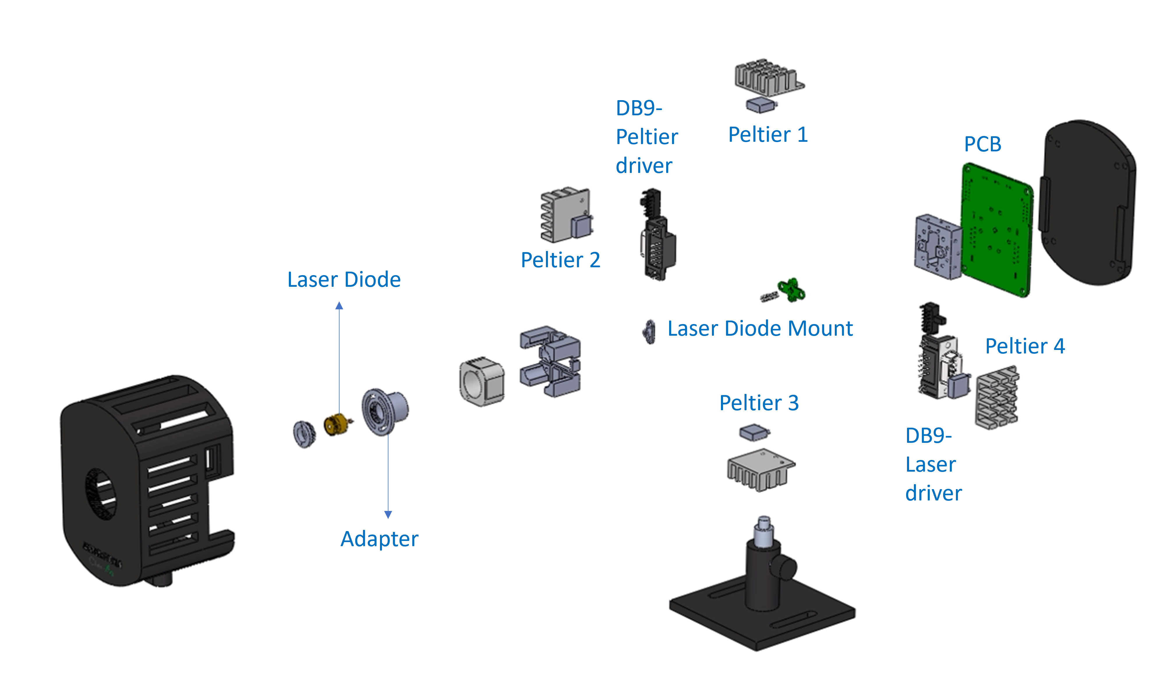
This exploded view reveals the meticulous engineering behind our high-performance laser cooling solution, the Jasper Picolo. Designed for demanding applications, the Picolo mount is centered around a powerful thermal management system. Instead of one, we've integrated four Peltier elements (Peltier 1, Peltier 2, Peltier 3, Peltier 4) to create a highly efficient TEC (Thermo-Electric Cooler) cooling stage.
The Jasper Picolo's versatility is a key feature. Its laser adapter is ingeniously designed to accommodate both 3.8mm and 5.6mm diameter laser diodes, ensuring compatibility with a wide range of laser modules. This exploded view shows the Laser Diode and its adapter fitting seamlessly into the Laser Diode Mount.
We've simplified the integration process by incorporating dedicated connections for both the laser and the cooling system. Two DB9 connectors are clearly visible: one for the DB9-Laser driver and another for the DB9-Peltier driver. This thoughtful design choice makes wiring straightforward and reduces potential points of failure. The entire system is managed by a central PCB (Printed Circuit Board), which orchestrates the precise control of both the laser and the TEC elements. The Jasper Picolo is more than just a mount; it's a complete, high-precision solution for your optoelectronic projects.
Product Design