Tony Francis
-
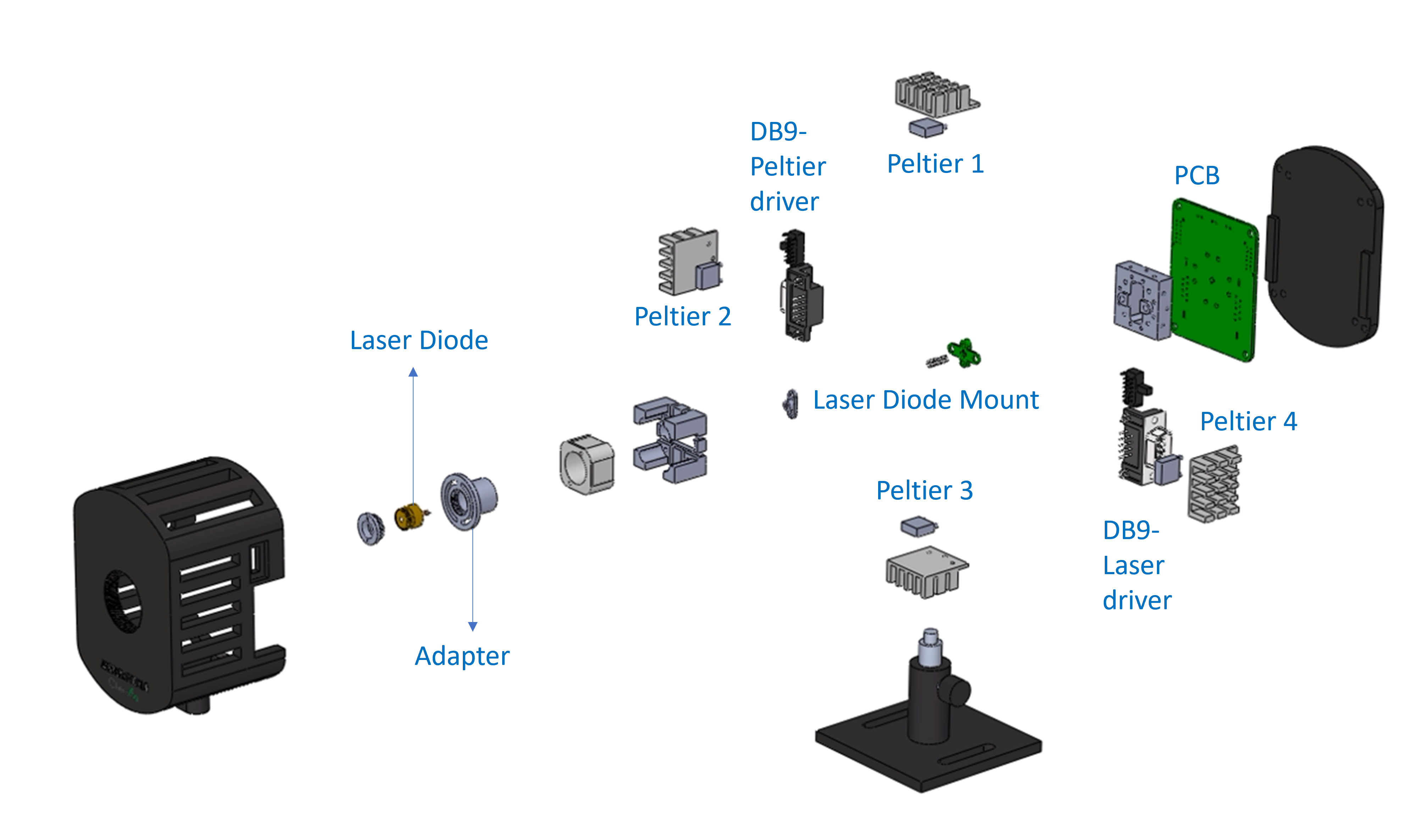
JASPER PICOLO Laser Mount Disassembly Video
08/15/2025 at 18:36 • 0 commentsWe've just released an exciting new video on the progress of our JASPER TEC controller build.
Get an in-depth look at the disassembly of the JASPER PICOLO, our temperature-controlled laser mount. This video provides a detailed view of its internal components, including the four Peltier elements and the DB9 connectors for the laser driver and TEC controller.
Watch the full video here: https://youtu.be/uEF8V3ZVT6c
Stay tuned! We'll be sharing more updates as we continue to build the mechanical mounts and the temperature controller electronics.
-
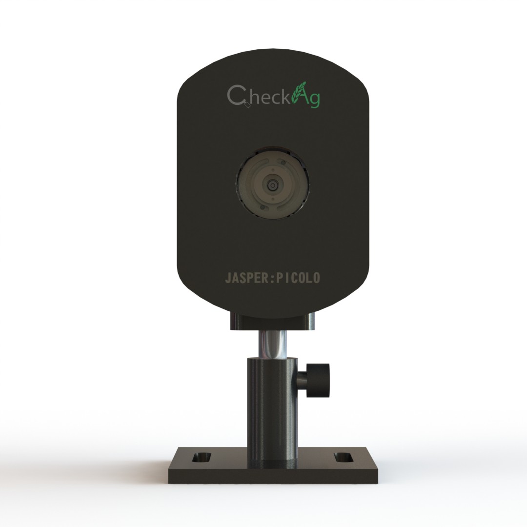
Announcing the Industrial Design of JASPER PICOLO
08/03/2025 at 18:28 • 0 commentsWe're thrilled to present the industrial design for our new temperature-controlled laser mount, the JASPER Picolo. This name stands for Precision Integrated Cooling for Optoelectronics and Laser Operations, and it's built to meet the rigorous demands of your work.
The Picolo is engineered for seamless integration into your existing setup. It features two M6 slots for stable mounting on an optical bench, and its optical height is fully adjustable with a variable length post mount, giving you precise control over your alignment.
To support a variety of projects, the mount is designed to accommodate multiple TO-can laser packages, including Ø3.8 mm, Ø5.6 mm, and Ø9 mm, as well as TO-46. Each package requires a specific adapter to ensure optimal thermal performance and stability.
For streamlined operation, the Picolo includes two DB9 connectors. One connector interfaces with a laser driver, and the other is for a TEC controller. While we are starting with the development of our TEC controller, we have future plans to develop a dedicated laser driver as well. This design ensures that the mount is future-proof and ready for a complete, integrated solution.
![]()
-
JAPSPER Update: Designing a 4-Element TEC Laser Mount
08/01/2025 at 18:32 • 0 comments![]()
JAPSPER, our open-source project for "Just Another Spectrometer," is all about making scientific instruments more accessible, repairable, and affordable. We've been working on a range of modules, and we're excited to share our latest mechanical design for a temperature-controlled laser mount using four Peltier elements.
Why Four Peltiers?
Most commercial or DIY designs rely on a single Peltier element, or maybe two, to cool the laser diode. This can lead to uneven cooling, which can affect the laser's performance and stability. To ensure uniform cooling and better thermal management, we've designed a mount with four smaller Peltier elements arranged to "engulf" the laser diode. This innovative design allows us to maintain a more consistent and stable temperature across the entire laser housing.
The mount is highly adaptable and features a laser adapter that can accommodate both 3.8mm and 5.6mm diameter laser diodes, making it a versatile solution for a variety of projects. We've also included two DB9 connectors—one for the laser driver and one for the TEC (Thermo-Electric Cooler) driver—to simplify the wiring and integration process.
We Need Your Expertise!
Now that the mechanical design is complete, we're moving on to the control systems. We're looking for feedback from the Hackaday community, especially from those with expertise in thermodynamics and control systems. We want to ensure that our control loop design will effectively manage the four Peltier elements to provide the precise and uniform cooling needed for high-performance spectroscopy.
What's your take on a four-Peltier design? Do you have any suggestions for the control system? We're eager to hear your thoughts and suggestions to help us refine this crucial component of JAPSPER!
-
Overview of RTDs, Thermocouples, and Thermistors
04/08/2025 at 18:13 • 0 comments1. Resistance Temperature Detectors (RTDs):

Platinum RTD Construction Elements RTDs operate on the principle that the electrical resistance of certain metals (typically platinum, nickel, or copper) increases with temperature. The sensor consists of a thin metallic wire or film, and its resistance is measured and correlated to temperature.
A common linear approximation for an RTD is given by:
- Rt: Resistance at temperature T.
- Ro: Resistance at reference temperature To (often 0 °C or 25 °C).
- α: Temperature coefficient of resistance (typically around 0.00385 °C^(-1) for platinum RTDs).
Pros
-
High Accuracy and Stability: RTDs are known for providing precise and repeatable measurements, particularly in the medium temperature range.
-
Linearity: Especially in platinum RTDs, the relationship between resistance and temperature is nearly linear.
-
Wide Operating Range: Although not as broad as thermocouples, RTDs work well in a range from approximately –200 °C to +850 °C (depending on the construction material).
Cons
-
Cost: Often more expensive than thermistors or thermocouples, particularly for platinum-based sensors.
-
Size and Response Time: They can be bulkier compared to thermistors, and their response time may be slower because of thermal mass.
-
Self-Heating: The excitation current used for measurement can cause self-heating, potentially leading to measurement errors if not properly managed.
Applications
-
Industrial Process Control: Due to their accuracy and stability, RTDs are widely used in chemical processing and industrial automation.
-
HVAC Systems: They are often employed in climate control systems where precise temperature regulation is needed.
-
Laboratory Measurements: Their excellent reproducibility and accuracy make them a standard choice for scientific research and calibration equipment.
2. Thermistors:

Thermistor NTC Elements Thermistors are temperature-sensitive resistors made from semiconductor materials. They have a highly nonlinear resistance change with temperature. There are two main types:
-
NTC (Negative Temperature Coefficient): Resistance decreases as temperature increases.
-
PTC (Positive Temperature Coefficient): Resistance increases as temperature increases (less common for temperature measurement).
The resistance change of an NTC thermistor is typically modeled using the Steinhart–Hart equation, but for many practical purposes a simpler beta (β) parameter equation is used:
- Rt: Resistance at absolute temperature T .
- Ro: Resistance at the reference temperature To.
- β: Material constant, typically ranging from 3000 to 5000 .
Pros
-
High Sensitivity: Thermistors can detect very small changes in temperature due to a large resistance change.
-
Cost-Effective: Generally less expensive than RTDs.
-
Compact Size: They can be manufactured very small, which is useful for embedded applications.
Cons
-
Non-Linearity: The response is highly nonlinear, which complicates the conversion of resistance to temperature and may require calibration or linearization circuits.
-
Limited Temperature Range: Typically effective in a narrower range (e.g., –50 °C to +150 °C) compared to RTDs and thermocouples.
-
Self-Heating: Because of their high sensitivity, even a small measurement current can cause self-heating errors if not properly accounted for.
Applications
-
Consumer Electronics: Thermistors are common in appliances such as ovens, computers, and automotive temperature sensing because of their affordability and small size.
-
Battery Management Systems: Their sensitivity makes them ideal for monitoring the temperature of batteries in portable electronics and electric vehicles.
-
Medical Devices: They are frequently used in devices requiring rapid temperature response within a limited range, such as digital thermometers.
3. Thermocouples:

Thermocouple construction elements Thermocouples utilize the Seebeck effect, where a voltage (emf) is generated at the junction of two dissimilar metals when there is a temperature difference between that junction and the other ends.
The voltage generated is approximately proportional to the temperature difference across the junctions:
- E: Thermoelectric voltage (in volts).
- Thot and Tcold: Temperatures at the hot (measuring) junction and the cold (reference) junction respectively.
- S: Seebeck coefficient (in volts per degree Celsius) its value depends on the specific metals used.
Pros
-
Wide Temperature Range: Thermocouples can measure temperatures from –200 °C to over 2000 °C, making them ideal for high-temperature applications.
-
Fast Response Time: They have little thermal mass, ensuring a quick response to temperature changes.
-
Robustness: Often built to withstand harsh industrial environments and rapid temperature fluctuations.
Cons
-
Lower Accuracy: They are generally less accurate than RTDs and require cold junction compensation to maintain precision.
-
Nonlinearity: The relationship between the voltage and temperature is nonlinear, necessitating complex calibration or conversion electronics.
-
Signal Levels: The generated voltages are very small (typically microvolts per degree Celsius), so the measurement system must have excellent noise rejection and amplification.
Applications
-
Industrial Furnaces and Kilns: Their ability to measure high temperatures makes them suitable for metallurgy, ceramics, and glass manufacturing.
-
Aerospace and Engine Monitoring: Thermocouples are used in environments where rapid temperature changes occur and broad measurement ranges are needed.
-
Power Generation: They are common in turbine engines and other applications where extreme temperatures are encountered
In spectrometer applications—where precision, stability, and rapid response are critical for maintaining the accuracy of optical measurements—the use of an NTC (Negative Temperature Coefficient) thermistor as the temperature sensor for the thermoelectric cooler (TEC) is highly advantageous. These applications often demand stringent thermal regulation because even minor fluctuations in temperature can lead to drift in the detector’s performance or changes in the optical alignment, ultimately affecting spectral resolution and sensitivity.
The primary benefit of an NTC thermistor in this context is its high sensitivity; its resistance decreases exponentially with increasing temperature, which makes it exceptionally capable of detecting very small changes in temperature. This high sensitivity enables a closed-loop control system to react swiftly and accurately to temperature deviations. In a TEC system, where rapid thermal management is essential to counteract environmental disturbances or self-heating effects due to the TEC's operation, the thermistor’s prompt response helps ensure that the detector or optical component remains at the intended temperature.
Another important factor is the ease of integration into the temperature control circuitry. NTC thermistors are typically implemented in a voltage divider configuration—a straightforward circuit that converts temperature-induced resistance changes into a measurable voltage difference. Although the thermistor’s response is nonlinear, this relationship is predictable and can be compensated through calibration, linearization circuits, or by using digital signal processing methods (such as look-up tables in a microcontroller). This calibration process is particularly manageable in spectrometer applications because the operating temperature range is often well defined and narrow, allowing for effective compensation of the thermistor’s exponential behavior.
Let us know what do you think about using an NTC for temperature sensing in Thermal loop. What additional suggestions or improvements might you have for optimizing this design?
-
Gemini Imagines: Temperature-Controlled Laser Mount with Peltier & Annular Ring (Our 4-Peltier Design Coming Soon!)
03/30/2025 at 18:39 • 0 commentsWe were amazed to see the power of AI when Gemini rendered images of a temperature-controlled laser mount featuring a Peltier element and an annular ring. This visualization sparked our own design efforts, and we're now developing a robust mechanical solution: a laser mount with four Peltier elements!
![]()
![]()
Stay tuned for our upcoming Hackaday post, where we'll dive deep into our 4-peltier design.
We'll detail the challenges, benefits, and mechanical intricacies of this approach.
-
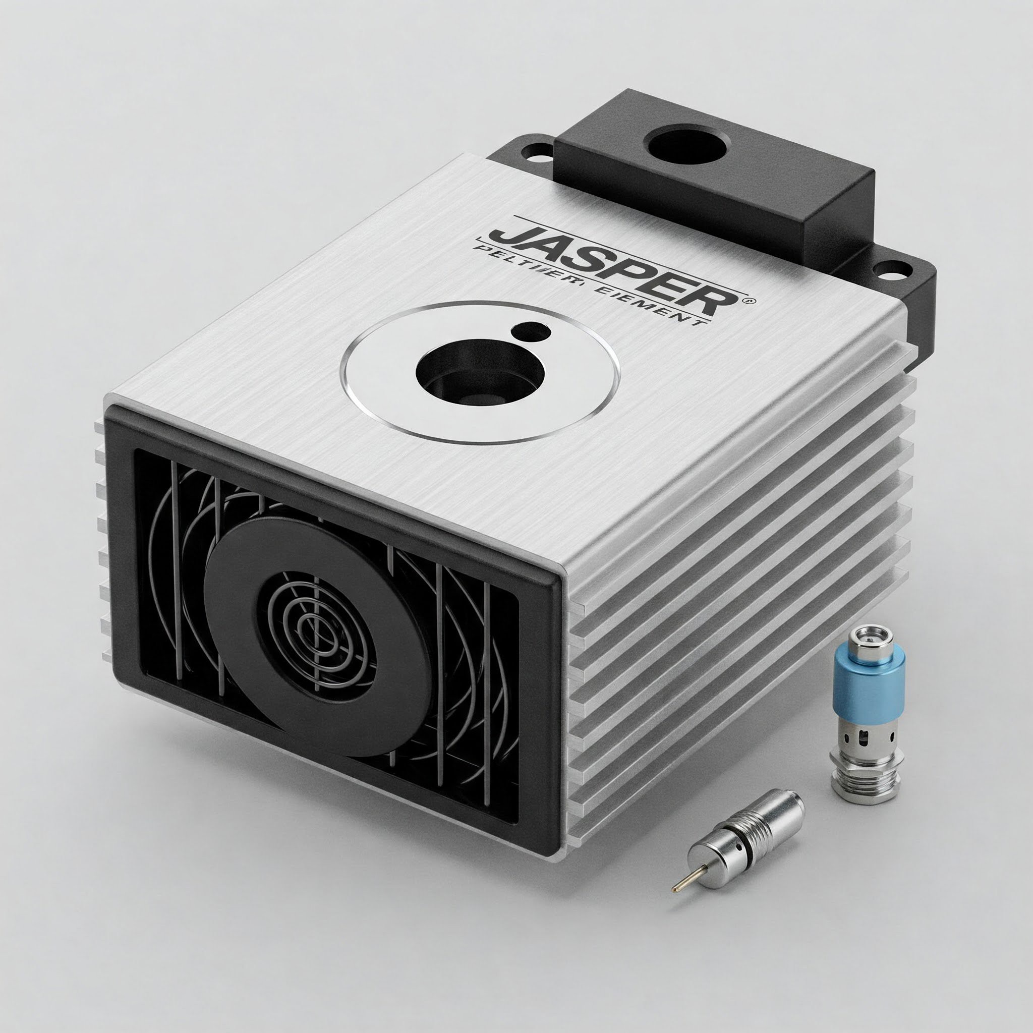
Exploring Peltier-Cooled Laser Mount Designs
03/24/2025 at 18:00 • 0 commentsExploring Peltier-Cooled Laser Mount Designs
![]()
Laser mounting systems often demand precise thermal management to ensure performance and stability. Here, we outline three innovative design options for a Peltier-cooled laser mount. Each approach leverages the unique cooling properties of Peltier elements to maintain the laser's ideal operating temperature.
1. Single Peltier with a Center Hole or Annular Ring This design features a single Peltier module with a central hole or an annular ring configuration. The laser is mounted in the centre, taking full advantage of the cold surface created by the Peltier effect. The simplicity of this design minimizes material usage and assembly complexity while delivering focused cooling where it’s most needed. However, effective thermal insulation around the laser and the Peltier module is essential to maintain efficiency.
Advantages:
- Compact and straightforward design.
- Cost-effective due to a single Peltier element.
Challenges:
- Cooling capacity is limited by the single module.
- Requires precise insulation to avoid thermal leakage.
2. Dual-Peltier System with an Aluminum Cold Plate In this design, two Peltier modules are mounted onto a heat sink, with the cold side transferring heat to a front aluminium plate. This plate serves as the cold mount for the laser, ensuring uniform cooling across the laser's surface. The aluminium plate adds structural integrity and improves thermal conductivity, making it ideal for applications requiring moderate cooling performance.
Advantages:
- Even heat dissipation across the aluminium cold plate.
- Increased cooling capacity with dual modules.
Challenges:
- Slightly more complex assembly due to the added heat sink and plate.
- Potential for uneven cooling if heat sink efficiency is compromised.
3. Four-Peltier System with a Central Aluminium Cube This ambitious design uses four Peltier elements mounted on each face of an aluminium cube. The cold center of the cube serves as the mounting point for the laser. This configuration provides multidirectional cooling, ensuring excellent thermal regulation for high-performance laser applications. The cube design adds symmetry and maximizes cooling efficiency, albeit at the cost of increased complexity.
Advantages:
- Superior thermal regulation due to multidirectional cooling.
- High cooling capacity for demanding applications.
Challenges:
- Complex assembly and higher material costs.
- Thermal balance across all four modules must be carefully managed.
Choosing the Right Design: The choice between these designs hinges on your specific application requirements. The single Peltier option is ideal for straightforward setups with modest cooling needs. The dual-Peltier system balances simplicity and performance, while the four-Peltier cube is well-suited for high-performance, precision applications.
Which design do you think will elevate your project to the next level? Let us know in the comments!
-
Precision Temperature Control with MAX1968 TEC Driver
03/11/2025 at 10:19 • 0 commentsIntroduction
Precise temperature control is critical in many applications, from laser diode operation to scientific instrumentation. Thermoelectric Coolers (TECs), also known as Peltier modules, offer a solid-state solution for both heating and cooling without moving parts. This project explores the implementation and optimization of a temperature control system using Maxim's MAX1968 TEC driver.
Unlike traditional heating/cooling systems, TECs can switch between heating and cooling by simply reversing current flow, making them ideal for maintaining stable temperatures within ±0.01°C. However, their control presents challenges due to thermal mass and response lag. This project documents my journey in understanding, simulating, and implementing an effective PID control system for TECs.
Hardware Setup
Initial Setup
I began with a minimal configuration using our custom PCB built around the MAX1968 TEC driver IC and Peltier setup with NTC. The circuit follows Maxim's recommended application with the H-bridge configuration for bidirectional current flow. Initial tests revealed significant thermal lag when using a larger TEC module, resulting in slow CTLI (Control Input) response.
Enhanced Setup
To address the thermal lag issues, I upgraded the testing platform with:
- High-efficiency Aluminium heatsinks with forced-air cooling on the hot side
- Two separate thermometers for reference: one on the hot side and one on the cold side
- An NTC thermistor embedded directly into the heatsink mounted on the TEC's cold side for faster and more accurate temperature readings
- Thermal compound to minimize interface resistance.
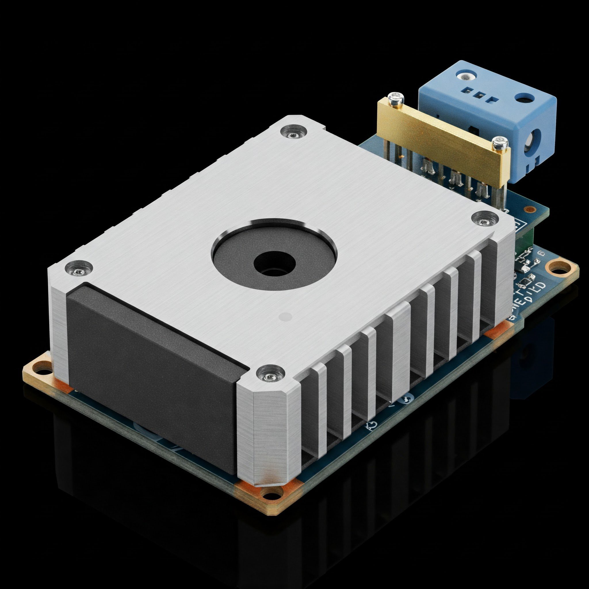
![]()
New setup with heatsink and thermometers The custom PCB implements the complete circuit shown in the schematic, including the PID control section with operational amplifiers (U7 and U9) configured according to Maxim Application Note 3318. The design includes:
- MAX1968 H-bridge driver for the TEC
- MAX4477ASA low-noise precision op-amps for the PID controller
- Configurable temperature set point via DAC
- Thermal feedback via NTC thermistor
- Power filtering and proper ground planes to minimize electrical noise
![]()
Custom PCB for MAX 1968 Understanding PID Control for TECs
Temperature control using TECs presents unique challenges due to their thermal response characteristics. According to Maxim Application Note 3318, TEC modules behave approximately like a two-pole system:
- First pole at an extremely low frequency (~20mHz)
- Second pole around 1Hz
This slow response creates significant phase shifts that can easily lead to oscillation in the control loop. The PID (Proportional-Integral-Derivative) controller must be carefully designed to maintain stability while providing adequate response time.
Key Aspects of the PID Controller Design
The PID controller for a TEC system requires careful component selection based on these formulas:
- For the integrator zero (prevents oscillation):
- fZ1 = 1/(2π × C2 × R3)
- With fZ1 = 70mHz and R3 = 243kΩ, C2 = 9.36μF (10μF used)
- For the differential network zero (cancels second pole):
- fZ2 = 1/(2π × C1 × R2)
- With fZ2 = 0.4Hz and R2 = 510kΩ, C1 = 0.78μF (1μF used)
- For the pole frequency:
- f3 = 1/(2π × C1 × R1)
- With f3 = 10Hz and C1 = 1μF, R1 = 15.9kΩ (10kΩ used for better phase margin)
- For high-frequency rolloff:
- fC = 1/(2π × C3 × R3)
- With fC = 30Hz and R3 = 243kΩ, C3 = 0.022μF
A critical insight: TECs have approximately four times stronger heating capacity than cooling for the same input current. This asymmetry creates a response variation of up to 6dB between heating and cooling modes, requiring robust phase margin in the control loop design.
Component Selection Considerations
For optimal PID performance, these component characteristics are crucial:
- Op-amp U1: Ultra-low leakage current (MAX4475ASA with 150pA max)
- Capacitor C2: Lowest possible thermal drift (polystyrene film ideal)
- Avoid electrolytic or tantalum capacitors in the compensation circuit
- Implement a guard ring around U1's inverting pin to intercept stray currents
- Use shielded wire for low-level thermistor signals
Simulation Work
To understand the dynamics of the PID control system, I performed nine simulation test cases with varying set points and thermistor values. The output of three op-amps was monitored: U3 (CTLI output to MAX1968) and the differential amplifiers U1 and U2.
Thermistor Response Tests (Fixed Set Point of 0.5V)
Test Case 1: Thermistor pulse 0V → 0.9V
This test simulated a condition where the thermistor reads significantly warmer than the set point. The CTLI output drove strongly negative to activate maximum cooling mode. The large delta between set point and thermistor value resulted in a pronounced response from the differential amplifiers.
Test Case 2: Thermistor pulse 0.5V → 0.4V
Here, the thermistor reads slightly cooler than the set point. CTLI showed a positive response to activate heating mode, though with smaller amplitude than Test Case 1 due to the smaller temperature difference.
Test Case 3: Thermistor pulse 0.5V → 0.6V
Similar to Test Case 1 but with a smaller temperature deviation. The response was proportionally smaller, demonstrating the linear control aspect of the PID loop.
Test Case 4: Thermistor pulse 0.5V → 1.0V
This test showed maximum negative CTLI output for maximum cooling when the thermistor reads significantly higher than the set point, demonstrating system saturation behavior.
Test Case 5: Thermistor pulse 0.5V → 0V
The opposite of Test Case 4, showing maximum positive CTLI output for maximum heating when the thermistor reads significantly lower than the set point.
Servo Regulation Tests
Test Case 6: Set point pulse 0V → 1V, Thermistor 0V
This test evaluated the system's response to a changing set point rather than changing thermistor values.
Test Cases 7-9: Various set point pulses with fixed thermistor at 0.75V
These tests further examined the system's ability to track temperature commands with different amplitudes and starting conditions. They demonstrated how the integrator action in the PID controller responds to sustained error signals.
Error Signal Calculation and Testing
The error signal in the control loop (at the output of U2) is calculated as:
Error = ((1.5V × R4)/(R4 + RT)) × (R4 + R5)/R4 - VSET
Where:
- 1.5V is the reference voltage
- RT is the resistance of the thermistor
- VSET is the voltage at SET POINT IN
- R4 = 10kΩ and R5 = 100kΩ in our design
Results Analysis
Initial Observations
The first tests with the larger TEC module revealed significant thermal lag, resulting in slow CTLI response. This manifested as temperature oscillations around the set point, indicating insufficient phase margin in the control loop. The main issues identified were:
- Thermal interface between the TEC and heat load was inadequate
- The thermistor placement was too far from the TEC surface, increasing response delay
- The initial PID component values didn't account for the larger thermal mass
Improved Performance
After implementing the enhanced setup with better heatsinks and optimized thermistor placement, the system showed marked improvement:
- Temperature stabilization time decreased.
- Steady-state temperature error reduced.
- Oscillations were significantly dampened.
The correlation between simulation and actual results was strong, validating the simulation approach. However, real-world testing revealed additional factors not captured in simulation:
- Ambient temperature fluctuations affected the system more than anticipated
- The thermal interface material's performance degraded slightly over time
- Power supply ripple introduced minor instabilities at specific operating points
The PID parameters required fine-tuning from the theoretical calculations, particularly:
- Reducing the proportional gain to prevent overshoot
- Increasing the integral time constant to improve steady-state accuracy
- Adjusting the derivative component to enhance response to rapid temperature changes.
Next Steps
PID Optimization
Future work will focus on further optimizing the PID parameters through:
- Systematic testing of different gain settings
- Implementing an auto-tuning algorithm for self-calibration
- Exploring advanced control techniques like feedforward compensation
Hardware Improvements
Planned hardware enhancements include:
- Designing a more compact PCB with improved thermal isolation
- Experimenting with different op-amp options for lower noise
- interfacing it with microcontroller to control the set point with DAC and monitor other necessary parameters digitally.
Conclusion
This project has demonstrated the successful implementation of a precision temperature control system using the MAX1968 TEC driver. Through simulation, testing, and iterative improvement, I've gained valuable insights into the challenges of thermal control systems.
The PID control approach, while conceptually simple, requires careful component selection and parameter tuning when applied to systems with significant thermal lag. The asymmetric behavior of TECs in heating versus cooling modes adds complexity that must be addressed for optimal performance.
The developed system provides a foundation for further exploration of applications requiring precise temperature control. The combination of simulation and real-world testing proved essential in understanding the system dynamics and achieving stable operation.
-
Precise Temperature Control in Optical Applications: Evaluating TEC Controller Reference Designs
03/04/2025 at 06:14 • 0 commentsPrecise temperature control is paramount in numerous optical applications, directly influencing the performance and stability of critical components.
Optical Applications Requiring Temperature Control:
- Laser Diode Wavelength Stabilization: Laser diodes exhibit a strong correlation between temperature and emitted wavelength. Even a minute temperature variation of just 1°C can induce significant wavelength drift, impacting the accuracy and repeatability of optical systems.
- Laser Diode Operating Range Maintenance: Certain laser diodes operate within a strictly defined temperature window. Maintaining this precise temperature range is essential for consistent lasing and optimal performance.
- Tunable Diode Laser Absorption Spectroscopy (TDLAS): TDLAS leverages the temperature-dependent wavelength tuning of diode lasers for high-sensitivity gas analysis.
- CCD/CMOS Detector Thermal Noise Reduction: Dark current, the thermally generated charge in CCD and CMOS sensors, significantly degrades image quality, particularly in low-light conditions. As a general rule, dark current doubles for every 5-10°C increase in temperature. Low dark noise is critical for applications like Raman Spectroscopy, astrophotography, scientific imaging, and medical diagnostics.
The specific demands of temperature control in optical systems vary significantly across applications. While thermal noise reduction in CCD/CMOS detectors necessitates achieving the lowest possible temperatures, Tunable Diode Laser Absorption Spectroscopy (TDLAS) requires exceptionally accurate and stable temperature regulation. Furthermore, the physical scale of temperature control differs; laser diodes necessitate precise control over a small area, whereas CCD/CMOS sensors require cooling of a larger surface.
Given these contrasting cooling requirements, a single design cannot optimally address all applications. Therefore, we have chosen to prioritize accurate and stable temperature control, focusing initially on laser diodes for spectroscopy applications. This targeted approach allows us to develop a high-performance TEC controller that excels in maintaining the critical temperature stability essential for precise spectroscopic measurements. Future iterations may expand upon this core technology to address the wider range of thermal management challenges present in other optical systems.
Evaluating TEC Controller Reference Designs: A Technical Insight
As we delve into the intricate world of TEC (Thermoelectric Cooler) controller designs, our approach is structured to ensure a comprehensive analysis. Here are the key evaluations and steps we are taking:
- Unidirectional Control: Our initial focus is on unidirectional control, where the TEC is driven for cooling, with ambient temperature utilized for heating. This will provide us with a fundamental understanding of the control system dynamics.
- Simulation: Using LTSpice, we will simulate an analog PID (Proportional-Integral-Derivative) controller to assess the figure of merits and influencing parameters. This simulation will offer valuable insights into the controller's performance and stability.
- Analog PID Implementation: Analog Devices offers a range of TEC controllers with analog PID control. This approach promises simplicity in design and potentially a minimal bill of materials (BOM), though cost considerations remain to be evaluated.
- TI Smart DACs (AFEx39xx): Texas Instruments has introduced an intriguing TEC controller featuring their Smart DAC technology. These devices boast 8/10/12-bit, 4-channel Smart DACs with voltage output, ADC (Analog-to-Digital Converter), EEPROM, and a PI (Proportional-Integral) loop for DC/DC-based TEC control. This innovative approach is certainly worth exploring.
- TI Reference Designs: Texas Instruments also provides multiple reference designs for TEC controllers, incorporating a buck-boost DC/DC converter and a PI controller.
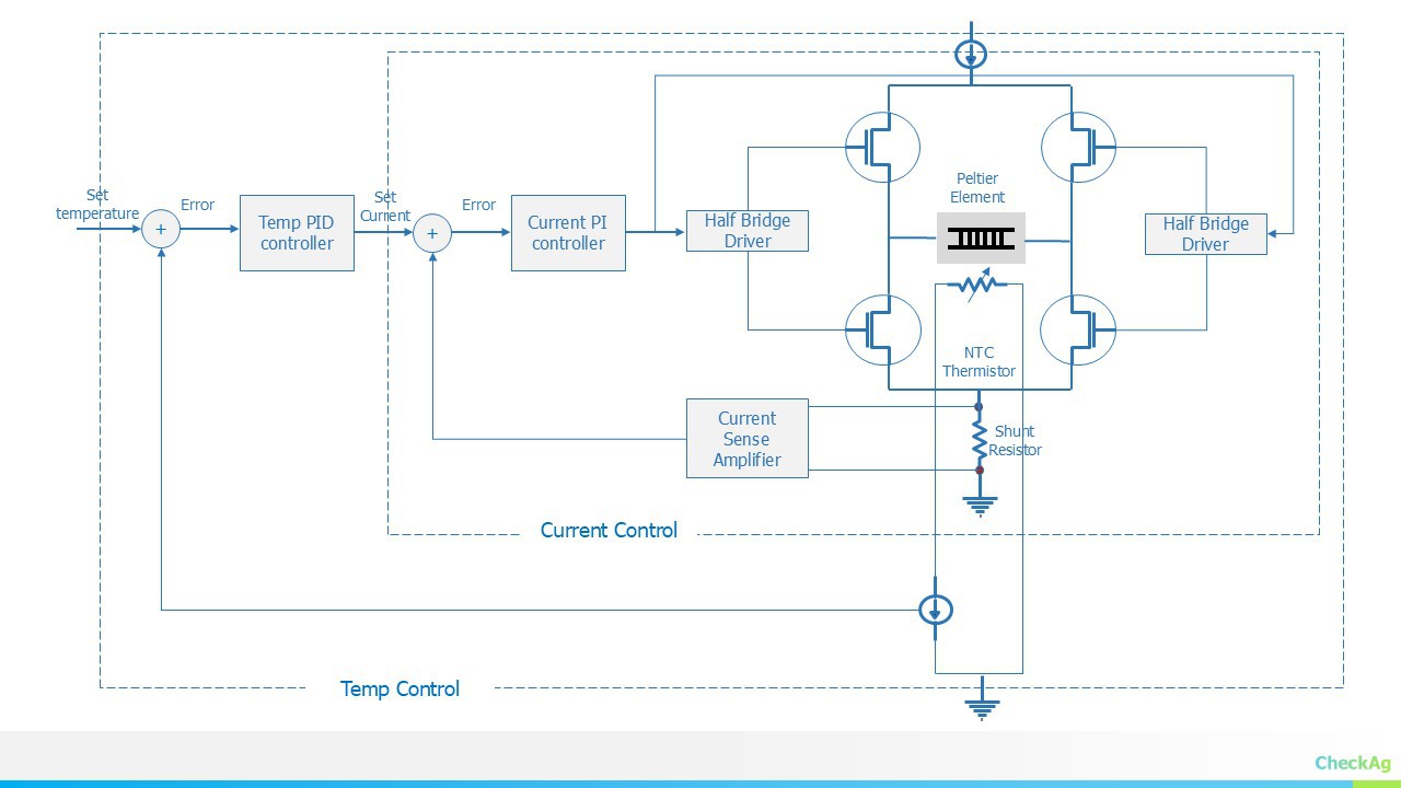
- Full-Featured Digital PID Controller: For those seeking the pinnacle of performance, a full-featured digital PID controller is the ultimate choice. This design features an outer loop PID controller for temperature control and an inner loop PI controller for current control. While this approach promises superior performance, it introduces significant design complexities.
![]()
As we continue our evaluations, we remain committed to exploring the intricacies of TEC controllers. The seemingly simple task of temperature control reveals itself to be a highly complex and fascinating subject.
For those interested in a deeper dive into the complexities of TEC control, we recommend exploring the paper "Bidirectional Modelling of Thermoelectric Module Using MATLAB/Simulink for Circuit Simulations" available at IEEE Xplore. https://ieeexplore.ieee.org/document/9847206
Stay tuned as we navigate this intricate landscape and share our findings. Your expert opinions and insights are invaluable to us as we embark on this technical journey.
-
Developing a TEC Cooler with PID Control: A Unidirectional Approach
03/03/2025 at 10:58 • 0 commentsAt CheckAG, we're currently developing a Thermoelectric Cooler (TEC) control system for precise temperature regulation — a critical part of many of our spectrometry projects. I wanted to share the initial steps of implementing PID control for the TEC and some design choices we've made along the way.
Understanding PID Control
PID control — Proportional, Integral, and Derivative control — is a widely used feedback control method for dynamic systems. It works by continuously calculating the error between the desired setpoint (target temperature) and the current value (actual temperature), then adjusting the output (PWM to the TEC module) based on three terms:
- Proportional (P): Reacts to the present error. The larger the error, the stronger the correction.
- Integral (I): Reacts to the accumulation of past errors. This term helps eliminate steady-state error.
- Derivative (D): Predicts future error based on its rate of change. It helps to dampen the response and prevent overshooting.
The control signal is computed as:
Output=Kp×Error+Ki×∫Errordt+Kd×d(Error)dt Output = Kp \times Error + Ki \times \int Error dt + Kd \times \frac{d(Error)}{dt}
In our setup, we used these initial PID constants:
float Kp = 420, Ki = 32, Kd = 1365;
Unidirectional Control for the Peltier Module
A key design choice we made is to use unidirectional control rather than bidirectional control. Typically, bidirectional control allows a Peltier module to both cool and heat by reversing the current flow. However, we opted for unidirectional control for two reasons:
- Simplicity: It reduces hardware complexity since we don't need an H-bridge or additional switching components.
- Ambient heating: When the MOSFET is off, the TEC naturally warms back to ambient temperature due to passive heat exchange. This allows us to rely on the environment to heat the TEC when necessary.
Our control logic works like this:
- MOSFET ON: The TEC cools down.
- MOSFET OFF: The TEC passively heats back up towards ambient temperature.
The PID controller's output is simply mapped to a PWM signal controlling the MOSFET’s gate:
analogWrite(PELTIER_PWM, controlSignal);
PID Tuning: Ziegler-Nichols Method
Tuning the PID gains is crucial to getting stable and accurate temperature control. We used the Ziegler-Nichols method for tuning, which follows these steps:
- Set Ki and Kd to zero.
- Increase Kp until the system oscillates at a constant amplitude — this is the ultimate gain (Ku).
- Measure the oscillation period (Pu) — the time it takes for one full oscillation cycle.
- Calculate Kp, Ki, and Kd using these formulas:
Kp Kd 0.5 * Ku 0 0.45 * Ku 0 0.6 * Ku Kp * Pu / 8 After tuning, we landed on:
Kp = 420;
Ki = 32;
Kd = 1365;
Final Thoughts
This unidirectional control design simplifies the hardware and leverages natural thermal dynamics to heat the TEC. The PID controller, tuned using Ziegler-Nichols, balances responsiveness and stability.
I'll continue to share updates as we refine the system further. Let me know if you'd like to dive deeper into any part of this — from the PID algorithm to the hardware design!
What do you think? I'd love to hear your thoughts, suggestions, or even experiences with TEC control systems!
JASPER: Peltier cooler for lasers
Peltier cooler for lasers used in FTIR and Raman spectrometers, maintaining temperature and wavelength stability for optimal performance