 danjovic
From Wikipedia article: The Cypher of the Monks
The Cistercian numeral system, a numeral system that was used by the Cistercian order of monks in the 13th to 15th centuries of the Middle Ages, and has been used sporadically since then. It allowed writing numbers from 1 to 9999 as single compound character (glyph)
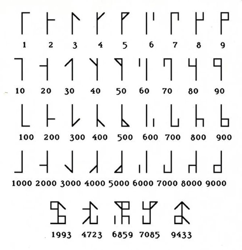
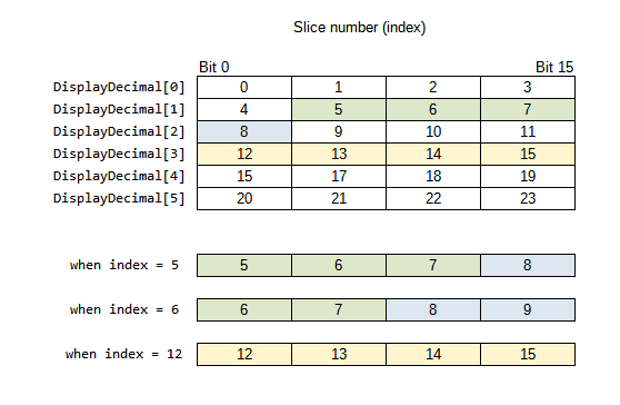
The Cistercian numbers can be represented minimalistically in a 4x4 dot matrix display, thus providing 4 digits to represent the time on a digital clock.
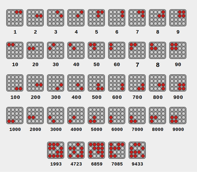
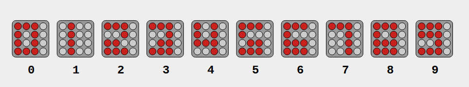
The Decimal numbers can also be presented on the 4x4 display and the decimal time can be displayed scrolling the digits row by row.
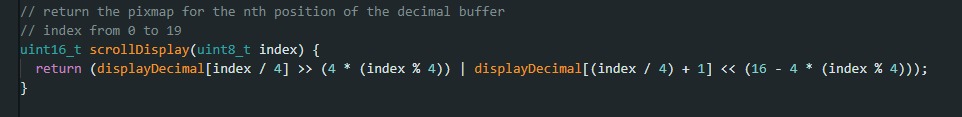
To perform the scroll, every digit is placed on an array of 16 bit numbers and the slices are taken sequentially to form the display, using the following expression.
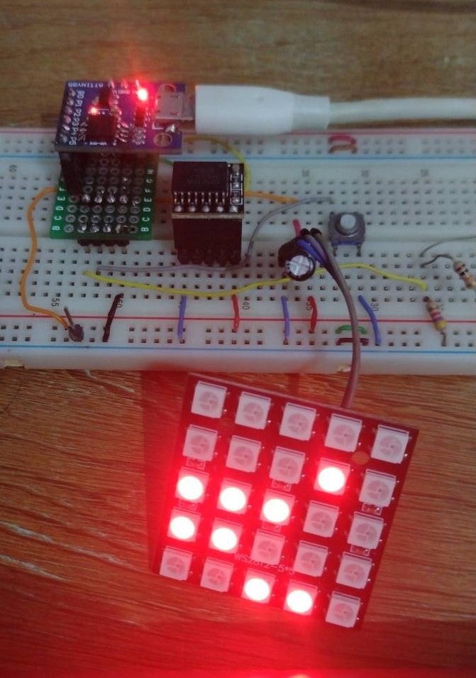
Neopixels
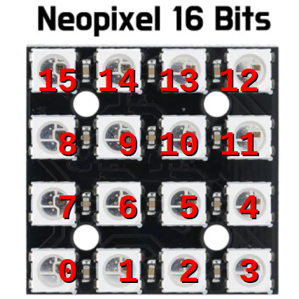
The display is based on WS2812 addressable LEDs. There are 4x4 led matrices available (but the prototype used a 5x5 that was already in my parts bin).
All that was necessary was a table to translate every bit of the display word into the position of the nth addressable LED.

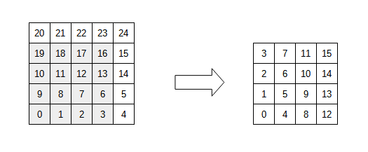
The translation would be necessary anyway because the arrangement of the 4x4 matrix do not follow order the pixels were mapped.
There is another array with the color of the every pixel of the display variable. The firmware allows to choose 1 out of 7 basic colors and a "random" color which is a random color for every quadrant of the display (4 pixels).
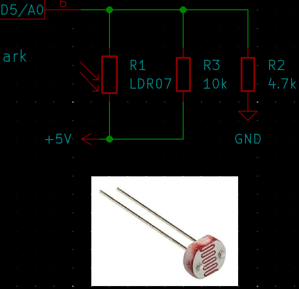
Auto Brightness level
The circuit provides an LDR to sense the ambient light at every second and adjust the LED brightness automatically.
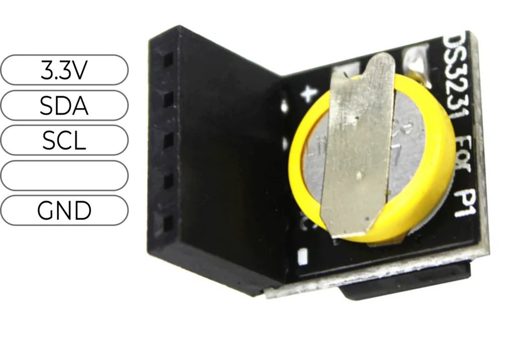
RTC
The clock timebase is a DS3231 module (aka PI RTC). The communication is with such module is performed using I2C.
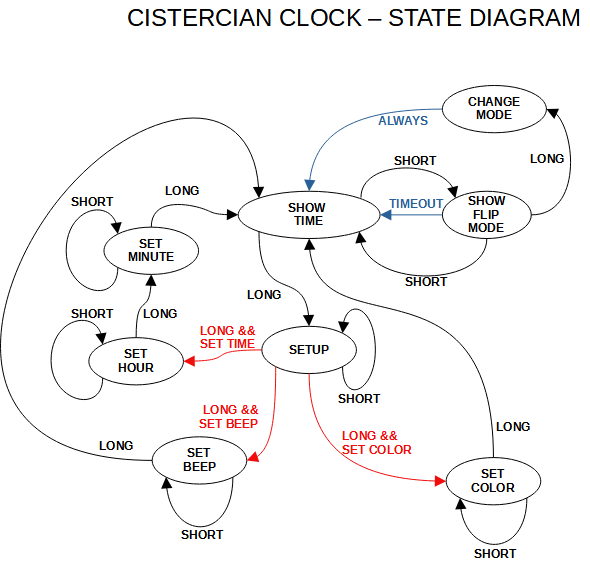
State Machine
The whole clock firmware was implemented around the a state machine that was designed to provide full operation and configuration using only one push button.
The first prototype was developed using an Arduino Nano and later the code was optimized to fit on a Attiny85 Digispark.
 Rahul Khanna
 ACROBOTIC Industries
 Patrick Hickey
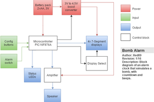
 Xed89
Xed89