 Georges Fayad
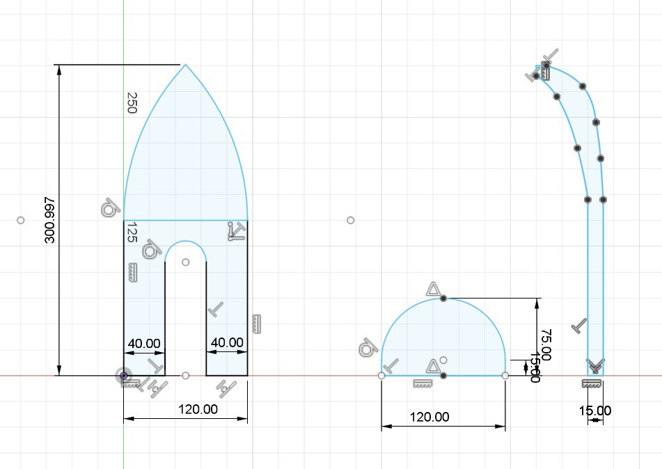
Here is the advancement on week three of the hull design
(High Speed) RC Boat using plywood
Already have an account? Log in.
To make the experience fit your profile, pick a username and tell us what interests you.
Here is the advancement on week three of the hull design
In this session we were able to make our boat run with the correct controls. we are able to steer using the dual rudders and we have both forward and backwards thrust from the motor. with all components fitting within the boat.
Everything was ready until the ESC controller broke and two precise soldering gave up, so now we're trying to find a pair of steady hands to fix it. Our final product should be presented today.
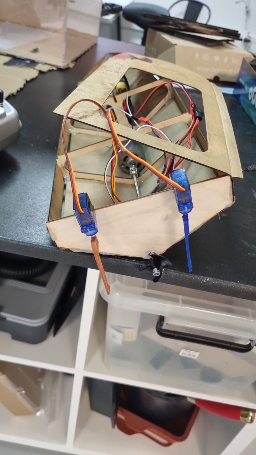
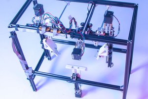
This week we starting with the location of where to place each part within the boat. we were able to mount the dual rudders on the back of the boat. we were also able to mount the engine so that the drive shaft goes through the back transom. this allows us to be able to drive the boat as well as steer. This is shown within the pictures. also shown in the pictures is the 'top deck' to cover the interior of the boat. with the hole in the middle we are still able to turn on the motor and also work on other components.
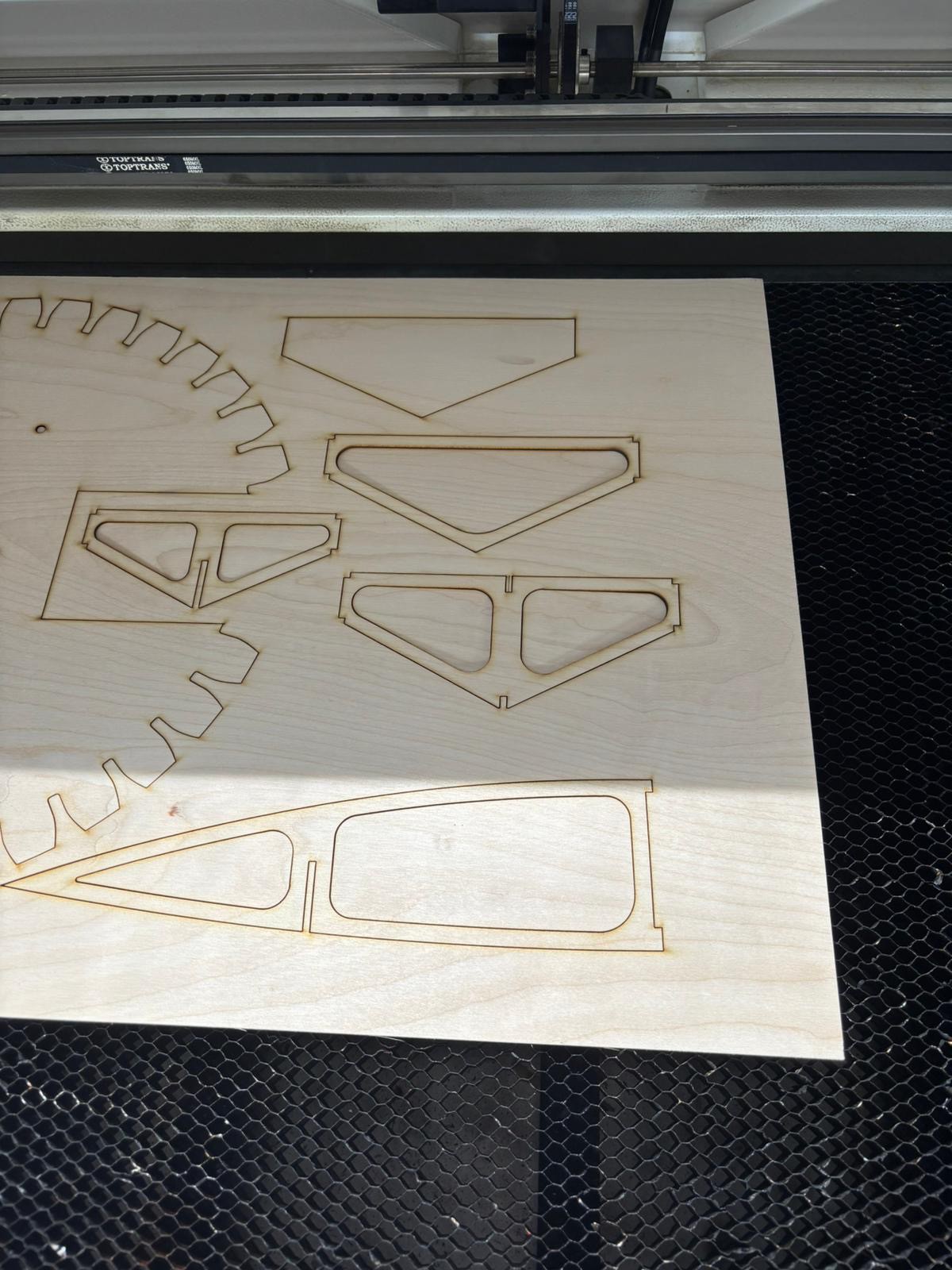
During this week our main goal was to create a prototype of the hull of the boat. We did this by using a laser cutter to be able to cut plywood to create the bulkhead and other supports for the hull. we created a rough prototype of the hull design with cardboard to make sure that our dimensions are accurate and to make sure that all of our components will fit within the boat without sacrificing any usability or balance.
Also pictured below is the laser cutting of the 'bulkheads' that are used to support the hull.
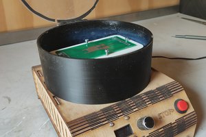
We were able to connect the motor and the micro servo motors to a mini receiver that allows us to control them with a RC controller. This allows us to have both forward propulsion and steering control. Attached is the photos of the components and how they are connected.
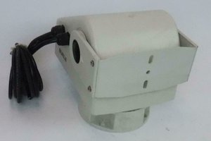
Today we finished the Fusion model but the wood we used for the laser cuter was too resistant to bending so we're going to use kerf bending Technics. On the motor part we ended up on brush less for the water resistance.
Diamètre : Ø35mm
Longueur : 34mm
Tours par volt (KV) : 1200
Puissance : 475W
Diamètre de l'arbre moteur : Ø4mm
Poids : 109g
Type de moteur : brushless à cage tournante (outrunner)
Consommation de courant max. A : 37A
Recommandation de batterie : 2S ou 3S LiPo
and we'll use propellers for propultion,
We have two choice for directions, either we use a servomotor of we use two brushless that we activate alternatively. Because we already have the servo we just have to command the brush less motors.
Днес завършихме модела Fusion, но дървото, което използвахме за лазерния резач, беше твърде устойчиво на огъване, така че ще използваме техника за огъване на бордюри. По частта на двигателя завършихме с по-малко четки за водоустойчивост.
Диаметър : Ø35mm
Дължина: 34 мм
Tours par volt (KV) : 1200
Мощност: 475W
Diamètre de l'arbre moteur : Ø4mm
Тегло: 109g
Тип на мотора : безчетков с турнантна клетка (outrunner)
Consommation de courant max. A : 37A
Recommandation de batterie : 2S ou 3S LiPo
И ще използваме витла за задвижване,
Имаме два избора за посоките, или ще използваме сервомотор, или ще използваме два безчеткови двигателя, които ще активираме алтернативно. Тъй като вече имаме сервомотор, трябва само да командваме двигателите без четки.
Today we did advance on two axis, first the hull model. With a new scrappy desing and some fusion sketches we got a pretty good view at the V1 of the project.
We also advanced on the motor axis, finding a model that can help having speed torque while being waterproof. The model we choose is a
두 번째 주에 인터넷에서 기존 설계도를 검색했지만 사용할 수 있는 설계도를 찾지 못했습니다.
We started our second week by looking for existent blueprints on the web, but couldn't find any that were relatable.
그러다가 Fusion 360을 사용하여 한 쪽에서는 엔진 작업을 하고 다른 쪽에서는 선체 스케치를 하면 작업을 더 효율적으로 나눌 수 있다는 사실을 깨닫고 직접 시도해 보기로 결정했습니다.
We then decided to try it ourselves when we realised that we could actually divide our work more efficiently by working on the engine, on one part and sketching the hull on the other, using Fusion 360.
ii Hola a todos !!
Hello everyone !!
Durante la primera clase, hemos realizado nuestro primer intento de proyecto utilizando cartón. Fue bastante difícil ya que no teníamos ni idea de cómo hacerlo, pero aún así encontramos una manera de concretarlo al final, como se muestra a continuación :
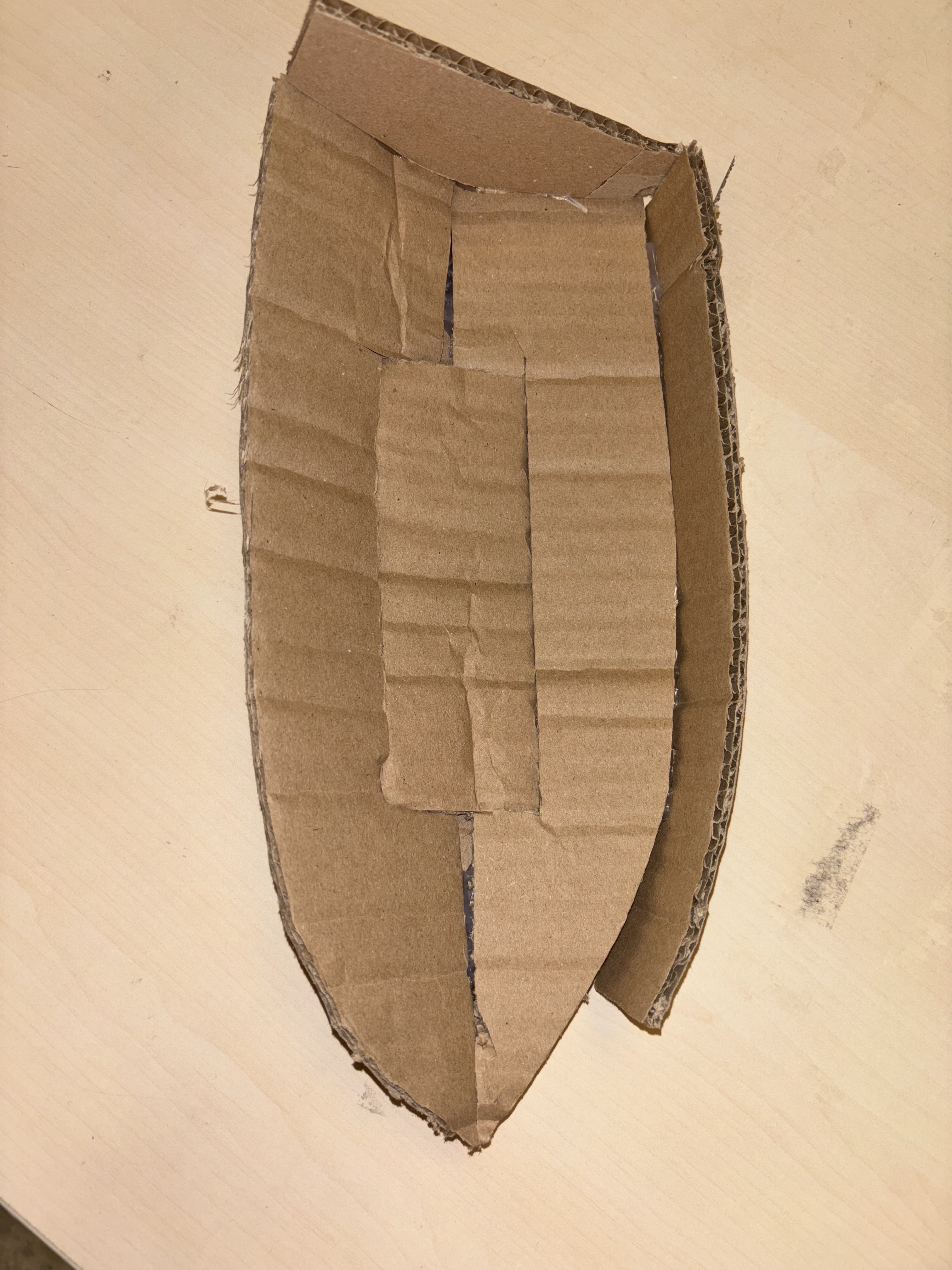
During the first class, we have made our first project attempt using cardboard. It was pretty hard since we had no clue how to make it, but still found a way to concretize it at the end, like shown below :
Usamos un poco de pegamento para hacerlo mas fuerte, y curvamos el carton para que pareciera un verdadero barco de rc. Desgraciadamente, con lo tontos que somos, lo pusimos en agua para ver si flotaba, pero el barco se ahogo debido a que el carton absorbia agua, y asi perdimos nuestro prototipo.
We used a few gluestick to make it stronger, and curved the cardboard to make it look like a real rc boat. Unfortunatley, as stupid as we are, we put it on water to see if it floats, but the boat drowned due to the coardboard absorbing water, and so lost our prototype.
Aún así, nos dimos cuenta de que la forma del barco estaba bien, y que teníamos que trabajar en ella, y probablemente dibujar primero un plano 2D para poder imprimirlo.
We still learnt that the shape of the boat was fine, and that we need to work on it, and probably sketch a 2D blueprint first in order to print it.
After analyzing the DXF, here’s a breakdown of typical parts (exact shapes may vary slightly):
| Part | Description |
|---|---|
| Base Keel Plate | Long central piece forming the spine of the hull |
| Bulkheads / Ribs | Vertical cross-sections with slots, numbered front to back |
| Side Panels (2x) | Long side shapes forming the hull's sides |
| Deck Plate | Top cover plate (flat or partially open) |
| Transom | Back end plate of the hull |
| Bow Piece | Front end plate of the hull |
Note: Some designs combine bow & deck or use symmetry for mirrored parts.
Material: Typically 3 mm plywood or acrylic
Kerf Compensation: If your cutter removes ~0.15 mm per cut, your slots should be slightly narrower
Label Each Part: Lightly engrave or mark each part with a pencil before removing them from the board
Lay the base keel plate flat on your workbench.
Make sure all slot cuts are clean (you can sand if needed).
Starting from the bow (front), insert each bulkhead into the matching slot on the keel.
The tabs should fit snugly. Use light pressure.
Ensure all bulkheads are perpendicular to the keel.
Slot the left and right hull side panels into the notches on each bulkhead.
This will shape the hull.
Use rubber bands or clamps to hold parts together temporarily.
Insert the transom (rear plate) and bow (front) between the two side panels.
These should lock into the side panels and bottom keel.
Once the internal frame is solid, place the deck over the top.
Make sure it matches the outer edges and locks with the bulkheads.
Use wood glue for assembly, followed by a marine-grade sealant or epoxy resin.
Sand lightly before sealing for better adhesion.
For electronics, consider building a removable waterproof hatch.
Sand sharp edges and corners.
Paint with waterproof or marine-safe paint.
Test float before installing electronics or motor.
Would you like me to:
Annotate or label the parts visually in the DXF?
Generate a 3D mockup or assembly image?
Provide printable instructions or a PDF version?
Let me know what would help you most!
Red wire from ESC → Motor terminal 1
Black wire from ESC → Motor terminal 2
(If the motor spins in reverse, swap these later.)
ESC's red (thick) → Battery +
ESC's black (thick) → Battery –
⚠️ Ensure connectors match (JST, XT60, etc.). Never reverse polarity.
Plug the ESC’s 3-pin servo-style connector into Channel 2 (for throttle) on the receiver.
Match wire orientation: Signal (white/yellow), Vcc (red), GND (black)
Servo 1 → Channel 1 (steering, or other control)
Servo 2 → Channel 3 or 4
Again, match polarity: GND (brown/black), Vcc (red), Signal (orange/yellow)
Your ESC most likely has a built-in BEC, which provides 5V to power the receiver through the same 3-pin cable.
You do not need extra wiring for receiver power.
Turn ON your transmitter first.
Then connect the LiPo to the ESC.
The receiver should light up and bind automatically, or follow your system’s bind procedure.
Use transmitter sticks to:
Control motor throttle (Channel 2)
Move servos (Channels 1, 3, or 4)


 Jeroen Delcour
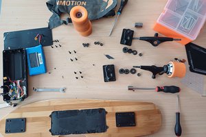
 Jrsphoto