 Silícios Lab
Introduction
The purpose of this project is to develop a printed circuit board (PCB) that allows weight measurement using a load cell and the HX711 converter. The electronic design community will be able to use this PCB for learning, experimenting, and implementing load measurement systems.
Click in this link to download the PCB Gerber file.

Load cells work based on mechanical deformation that generates a variation in electrical resistance, converted into an electrical signal proportional to the weight applied. The HX711 is a high-precision analog-to-digital converter (ADC) designed to amplify and digitize these weak signals, allowing direct interfacing with microcontrollers. In this project, we will use the ESP32 to read the HX711 and process the data obtained.

This project can be applied in several areas, including electronic scales, load monitoring in structures, and IoT systems for remote weighing.
Click in this link to download the PCB Gerber file.
Printed Board Specifications
The PCB was designed to be compact and optimized for accurate weight measurements. Below are the main specifications and features of the board:
Dimensions and Layout: The PCB has a compact design, allowing easy integration into different applications. The tracks were strategically positioned to minimize interference and optimize communication between components.
Main Components:
- Load cell: Responsible for converting the applied force into an electrical signal proportional to the weight.
- HX711: 24-bit analog-to-digital converter that amplifies and digitizes the signal from the load cell.
- Power and communication connectors: Allow interfacing with the ESP32 and proper powering of the circuit.
- ESP32 as a microcontroller: Responsible for processing the data acquired by the HX711 and communication with other devices.
- 100nF decoupling capacitor: Helps stabilize the HX711 power supply, reducing noise and improving reading accuracy.
Power supply: The board can be powered by 3.3V or 5V, making it compatible with different microcontrollers and applications.
Interfaces and Connectors:
- Load cell connector (4 wires): Allows direct connection of the load cell to the circuit.
- Digital communication pins (HX711 -> ESP32): Responsible for transmitting the measured data.
- Power supply and expansion terminals: Allow the addition of external modules, such as displays or wireless communication.
This project was developed with the aim of providing an affordable and reliable solution for weight measurements. Below, images of the PCB will be presented for a better understanding of the circuit design and layout.
Click in this link to download the PCB Gerber file.
Sensor and IC HX711 Operation
To understand how the HX711 and the load cell work, it is essential to know the operating principle of these components. The load cell converts the applied force into a variation in electrical resistance, which in turn generates a small voltage difference. However, this signal is extremely weak and requires amplification to be processed properly.
The HX711 plays this role by amplifying and converting the analog signal into digital, enabling it to be interpreted by a microcontroller such as the ESP32. In addition, the HX711 has a simplified two-wire interface for communication with microcontrollers, making its integration easy and efficient.
Below was presented all electronic schematic of the electronic circuit.
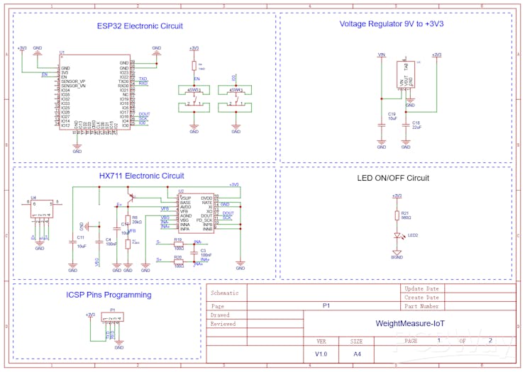
Next, we will explain in more detail the operating principle of the load cell.
Click in this link to download the PCB Gerber file.
Load Cell Operating Principle
The load cell is a transducer that converts mechanical force into electrical resistance variation.
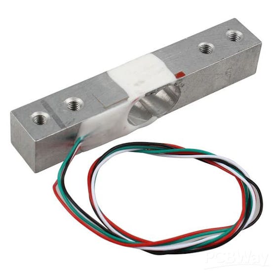
This variation is measured by a Wheatstone bridge, generating a small voltage signal proportional to the applied weight.
HX711 Amplification and Conversion
The HX711 is a 24-bit ADC designed to measure weak signals from load sensors. It amplifies the load cell signal and converts it to...
Read more »