 Arnov Sharma
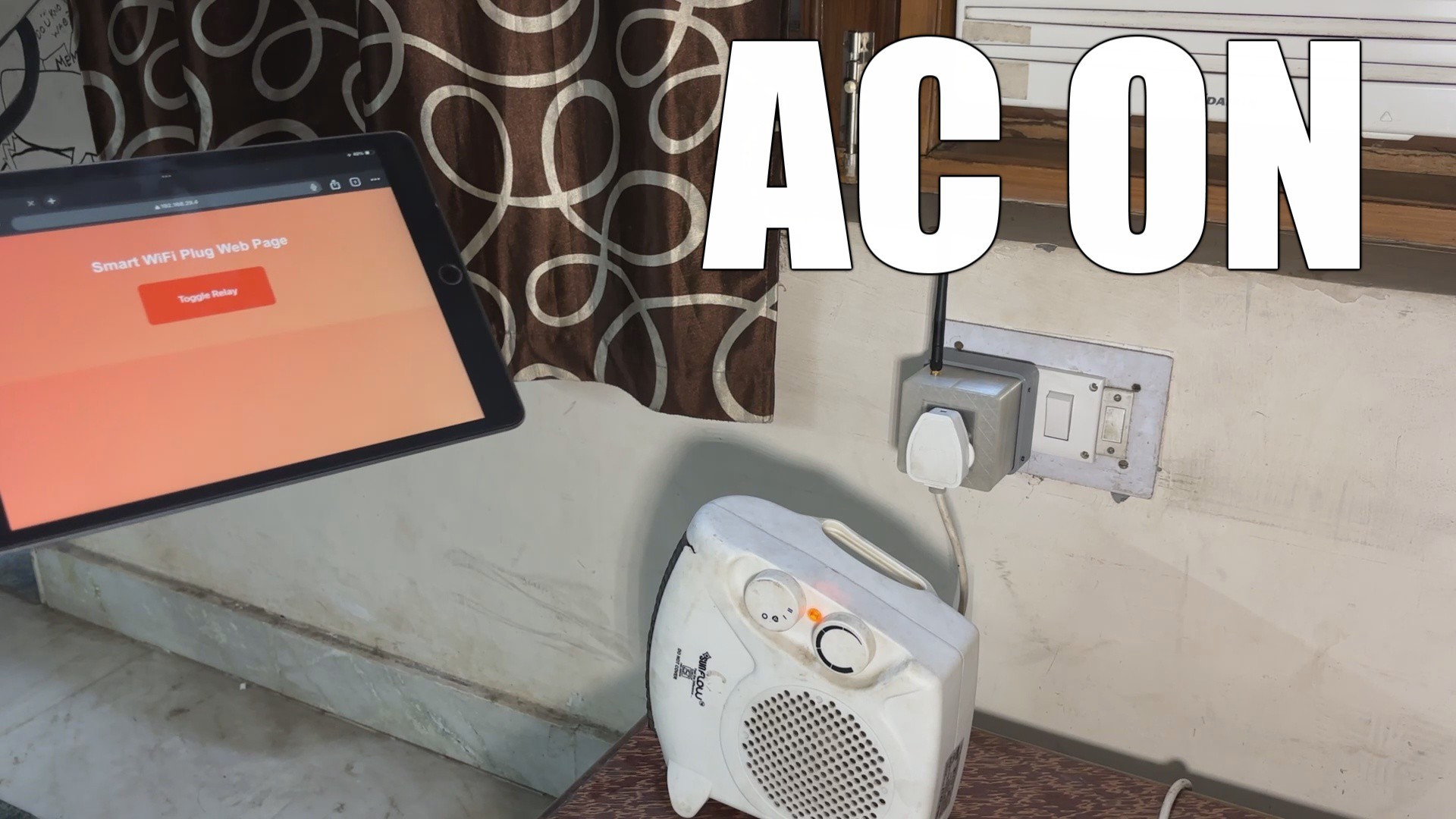

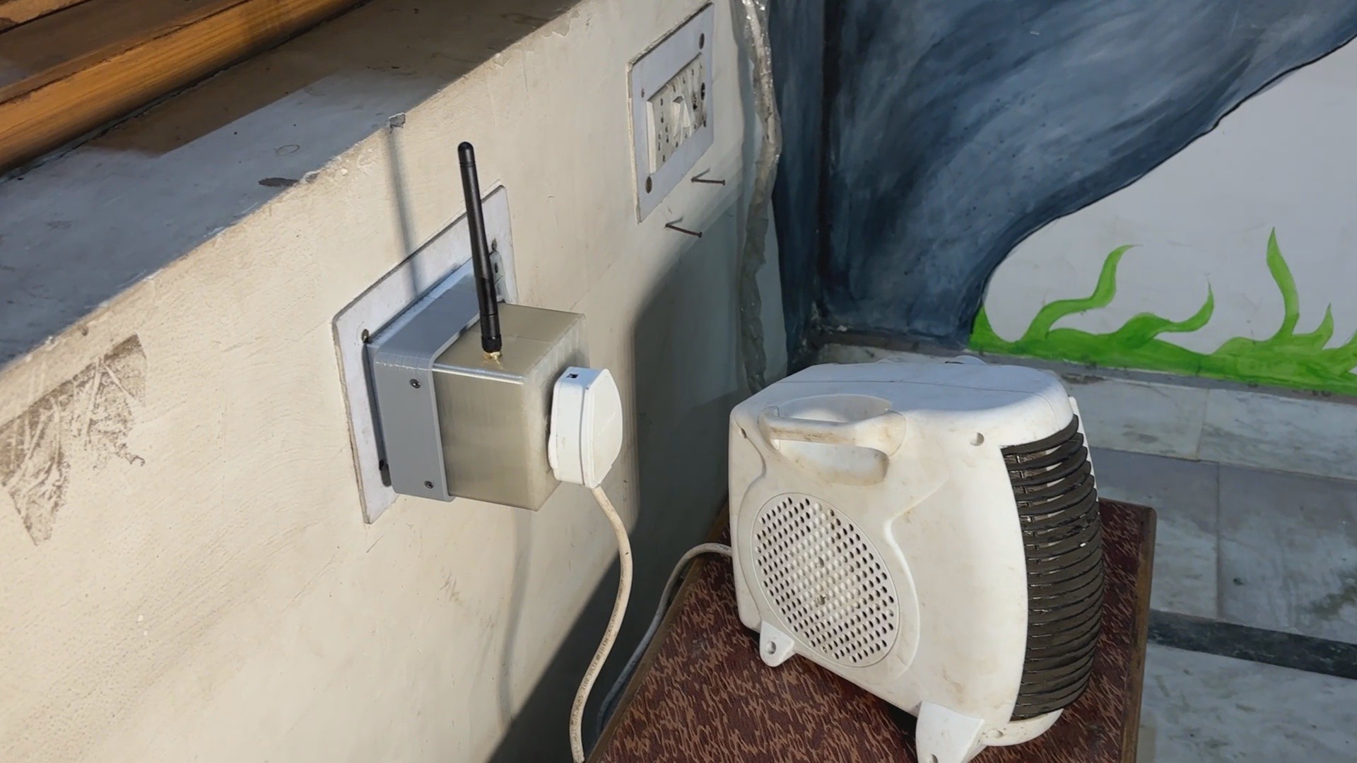
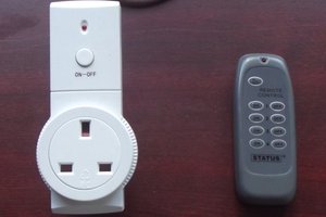
The idea was great but developing an IOT room heater that can only be used in the winter would be a waste, so we created the Smart Plug, which can be used with the room heater in the winter and with an air conditioner in the summer.
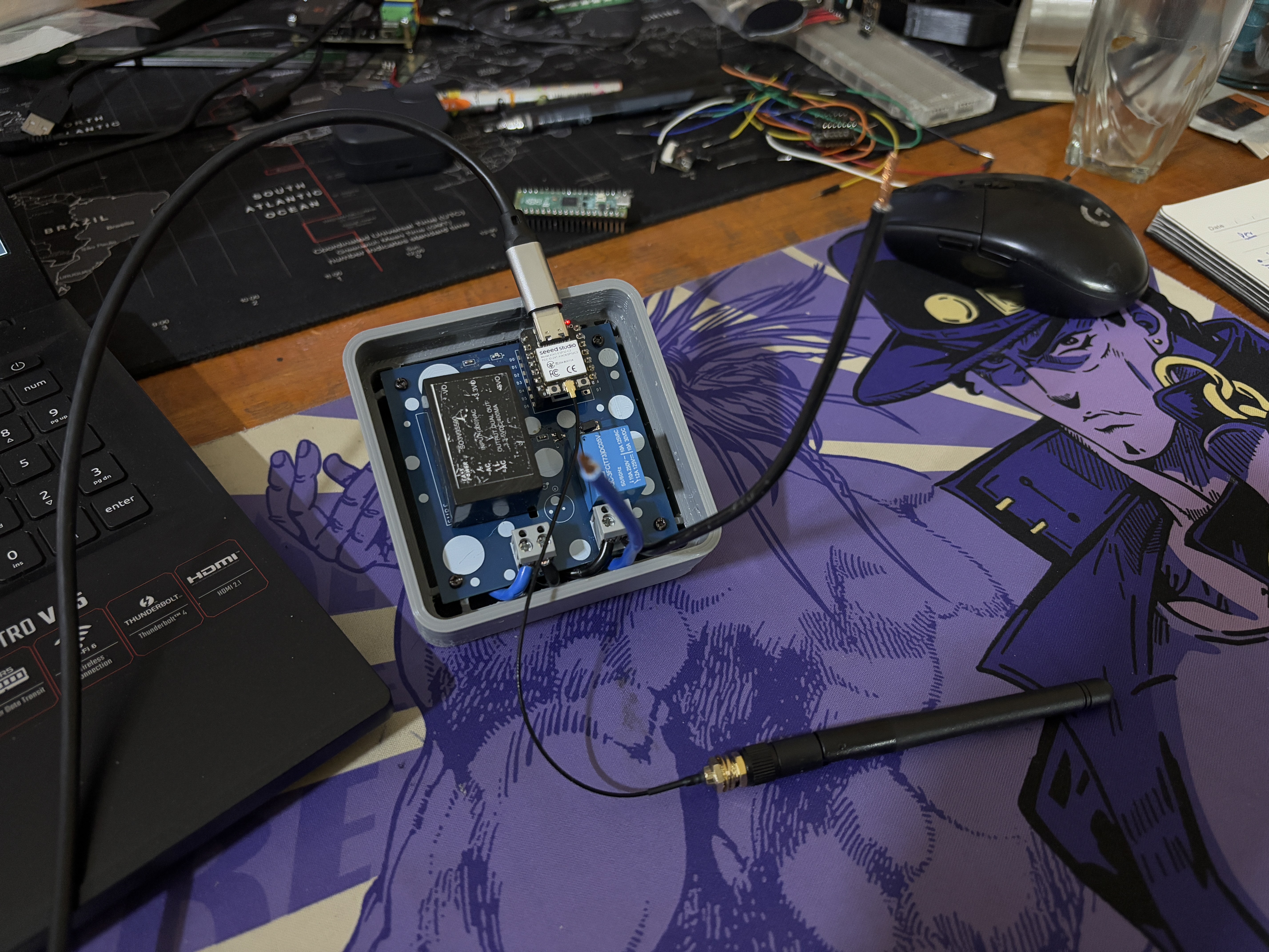
The Smart Plug consists of a single XIAO ESP32 C3 microcontroller linked to a custom relay board, which also houses an isolated 240V to 5V power source to power the XIAO and relay configuration.
Using a Web app, customers may effortlessly turn the gadget on or off from their tablets, smartphones, or PCs.
This article covers the entire build process for this project, so let us get started.
Design of the Plug


We begin the design process by using the previously developed XIAO RELAY driver board, as well as a socket and plug.
Before proceeding with the model, we needed to reduce the size of the plug and socket as much as possible; thus, we clipped away any extra material while retaining the essential components of both socket and plug. Both the plug and socket housing are built of thermal-grade PC, which can withstand the heat generated by the plug when plugging in a higher power load; this heat might easily melt the PLA if we made our own socket from scratch; thus, we had to incorporate PC material for the socket and plug into our model as well.
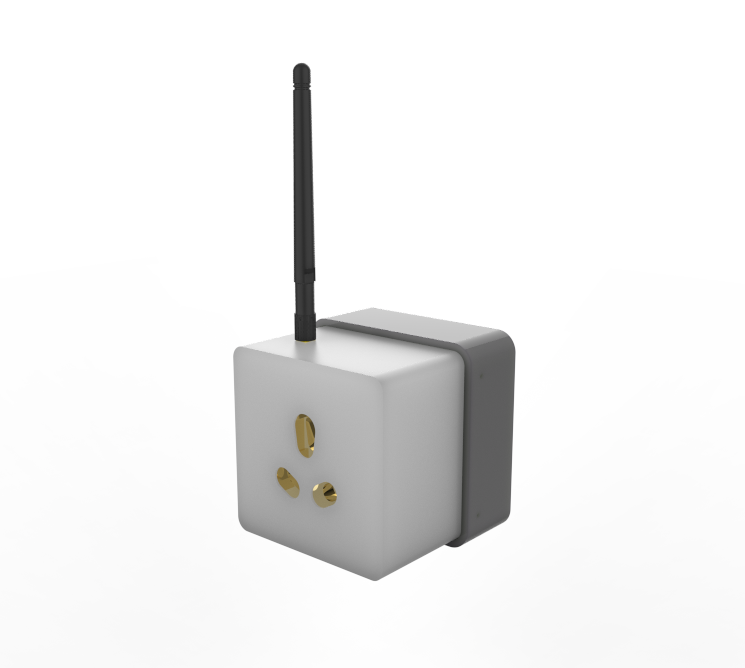
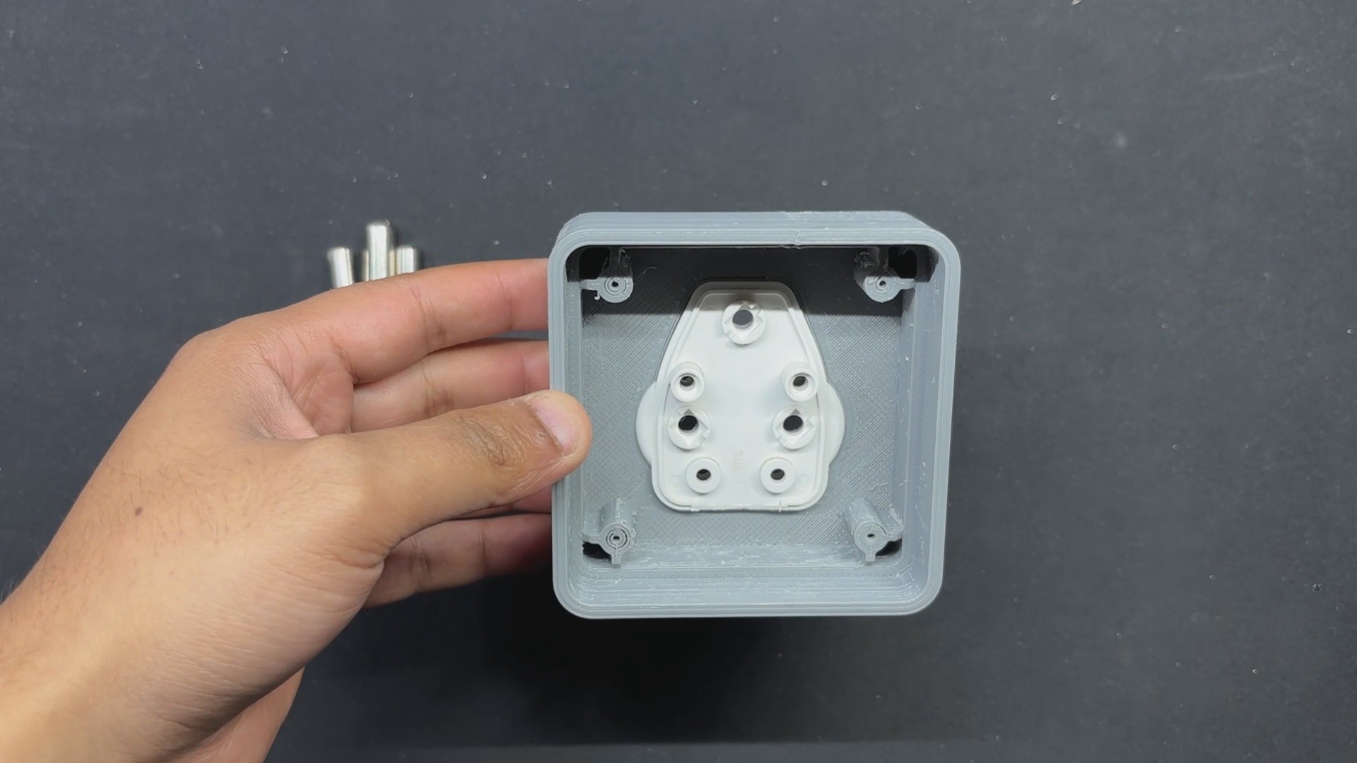
The model for this project is separated into two components or sections: the socket section and the plug section.
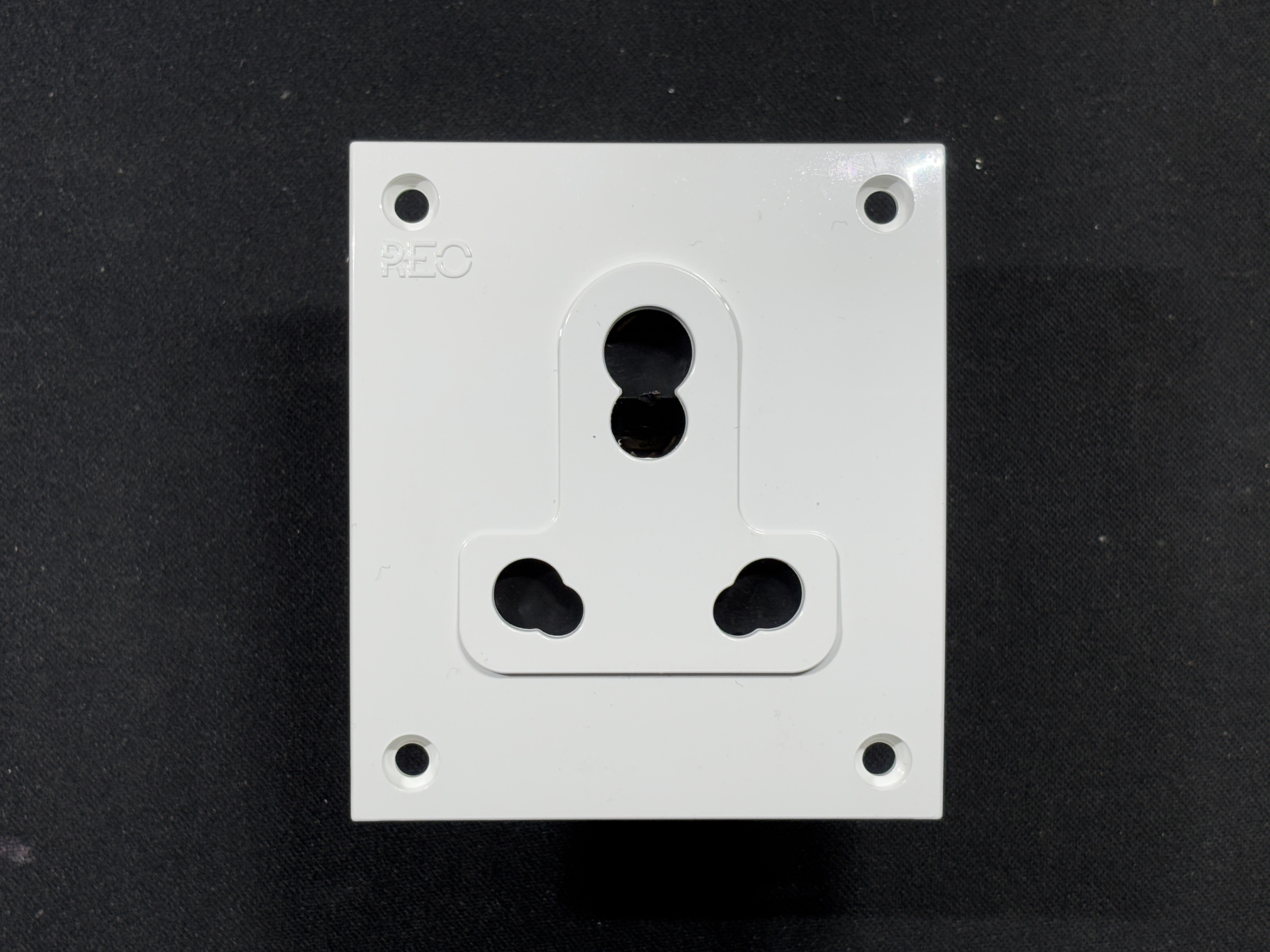
We are in India, and we use BS 546 Plug socket type, which includes two-pole and earthing-pin plugs, socket outlets, and socket-outlet adaptors for AC (50-60 Hz) circuits up to 250 V." It describes four plug sizes rated at 2 A, 5 A (Type D), 15 A (Type M), and 30 A.
The plug section is the back part where we have mounted the plug and circuit. Over the Plug section, we have the socket section, which includes the socket part and the WiFi antenna.
Both sections are held together with M2 screws from both sides.
To achieve a two-color theme, we printed the socket part in transparent PLA and the plug section in gray PLA using a 0.4mm nozzle and 0.2mm layer height.
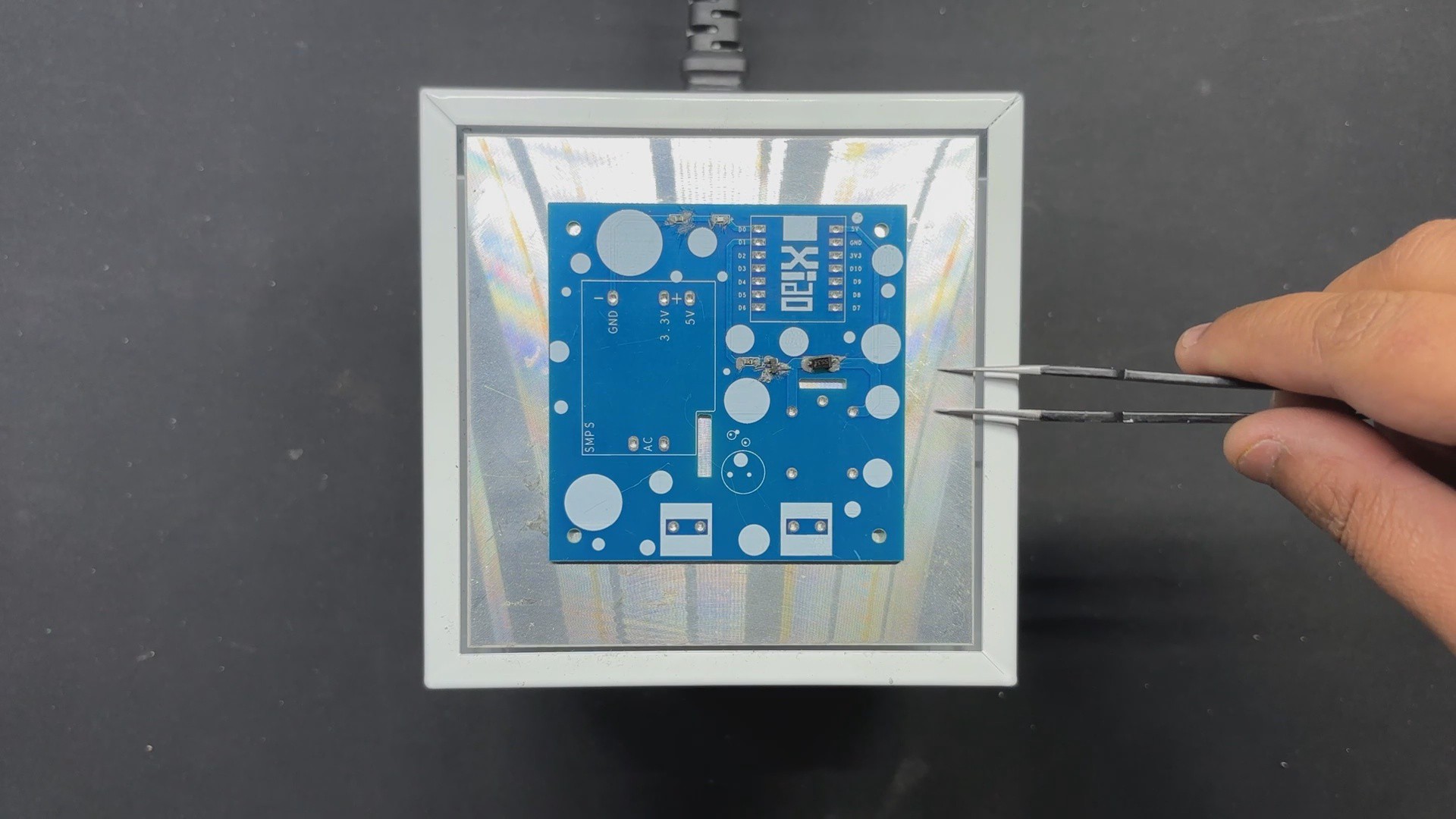
PCB Design: XIAO RELAY Board
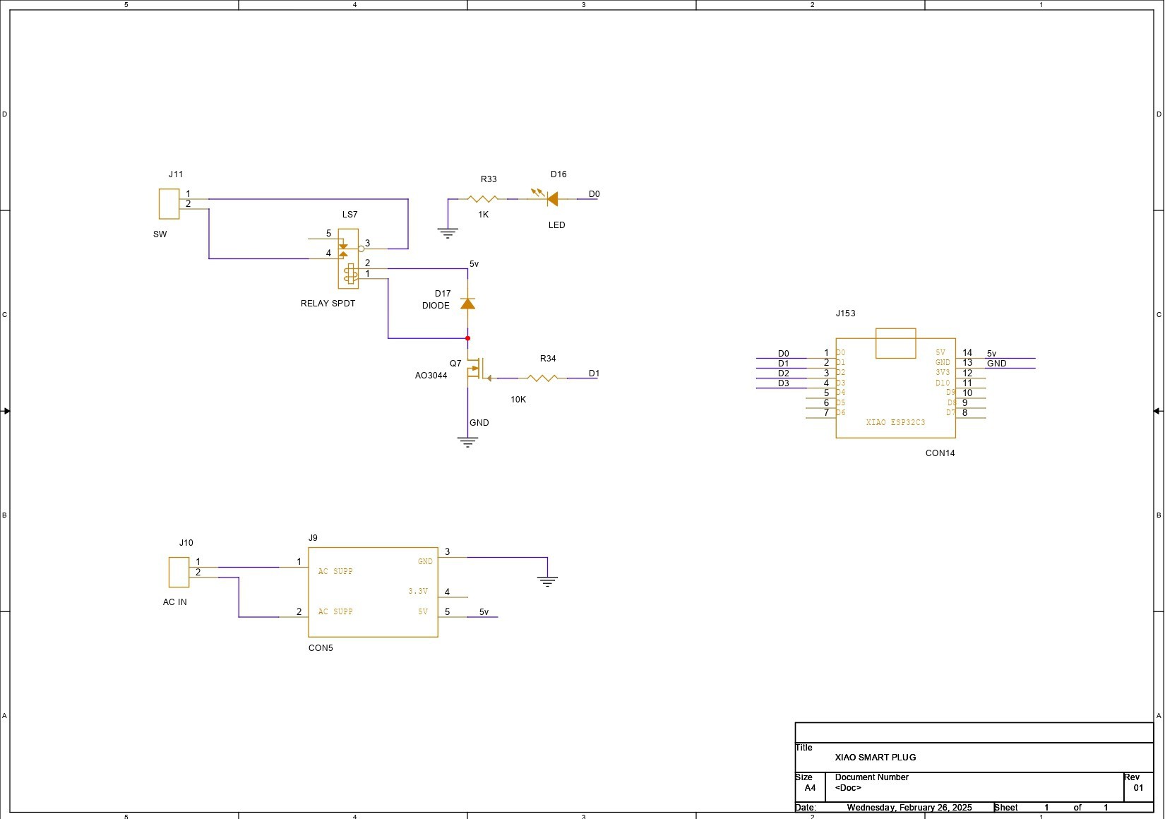

For this project, we are repurposing one of our past projects, the XIAO RELAY BOARD. It's a simple XIAO breakout board with a relay attached to a Mosfet as a switch controlled by the XIAO microcontroller.
We're utilizing an N-channel mosfet here, the AO3400 n-channel mosfet, with an AC-isolated Powers supply module installed on the board to deliver 5V from 240V AC.
https://www.hackster.io/Arnov_Sharma_makes/xiao-home-automation-board-4c0256
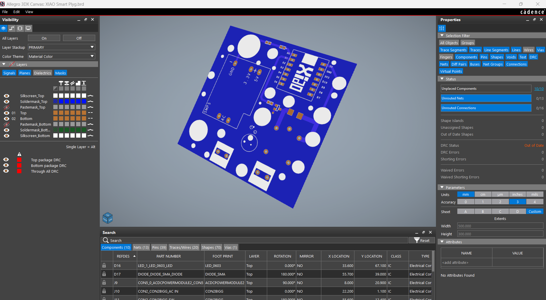
Seeed Studio Fusion Service

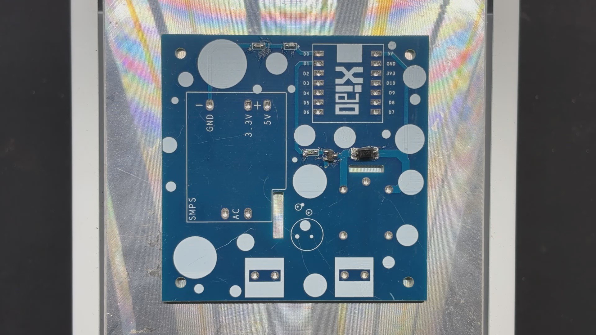
After finalizing the PCB and generating its Gerber data, we sent it to SEEED STUDIO FUSION for samples.
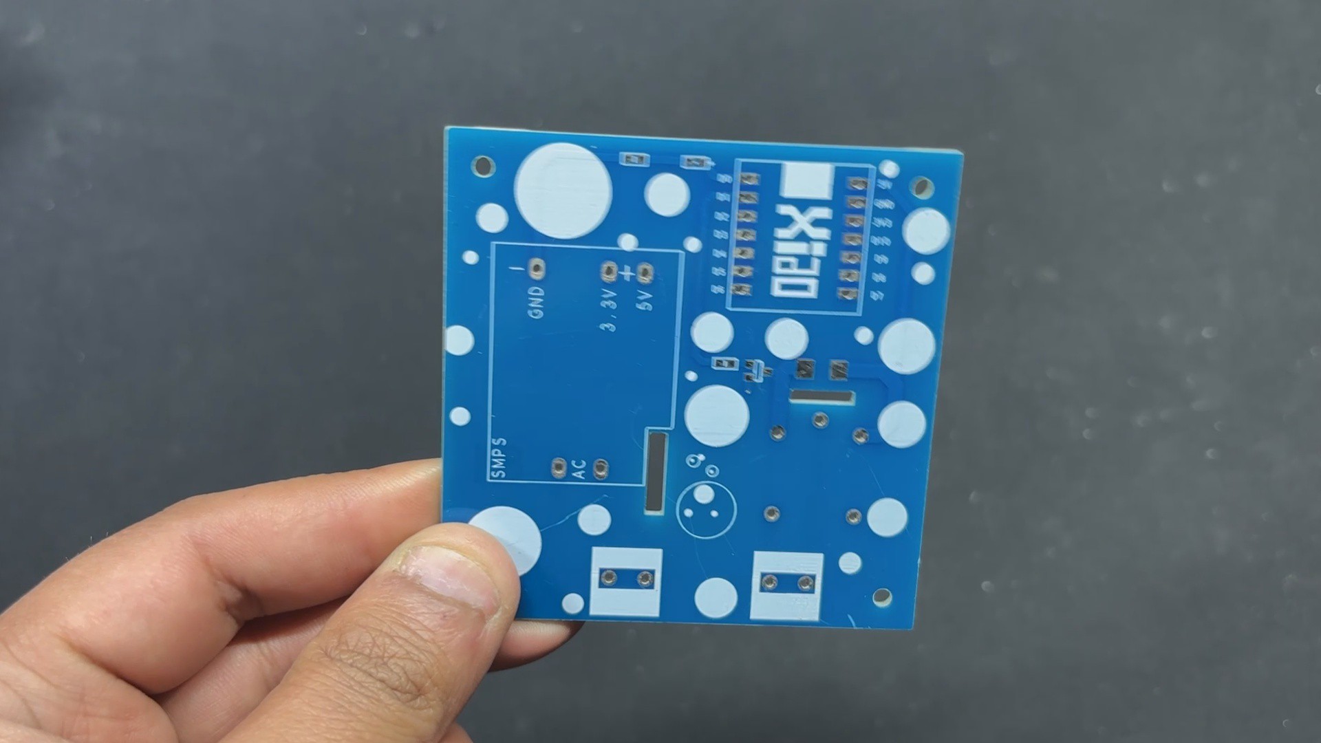
PCB was ordered in the blue solder mask with white silkscreen.
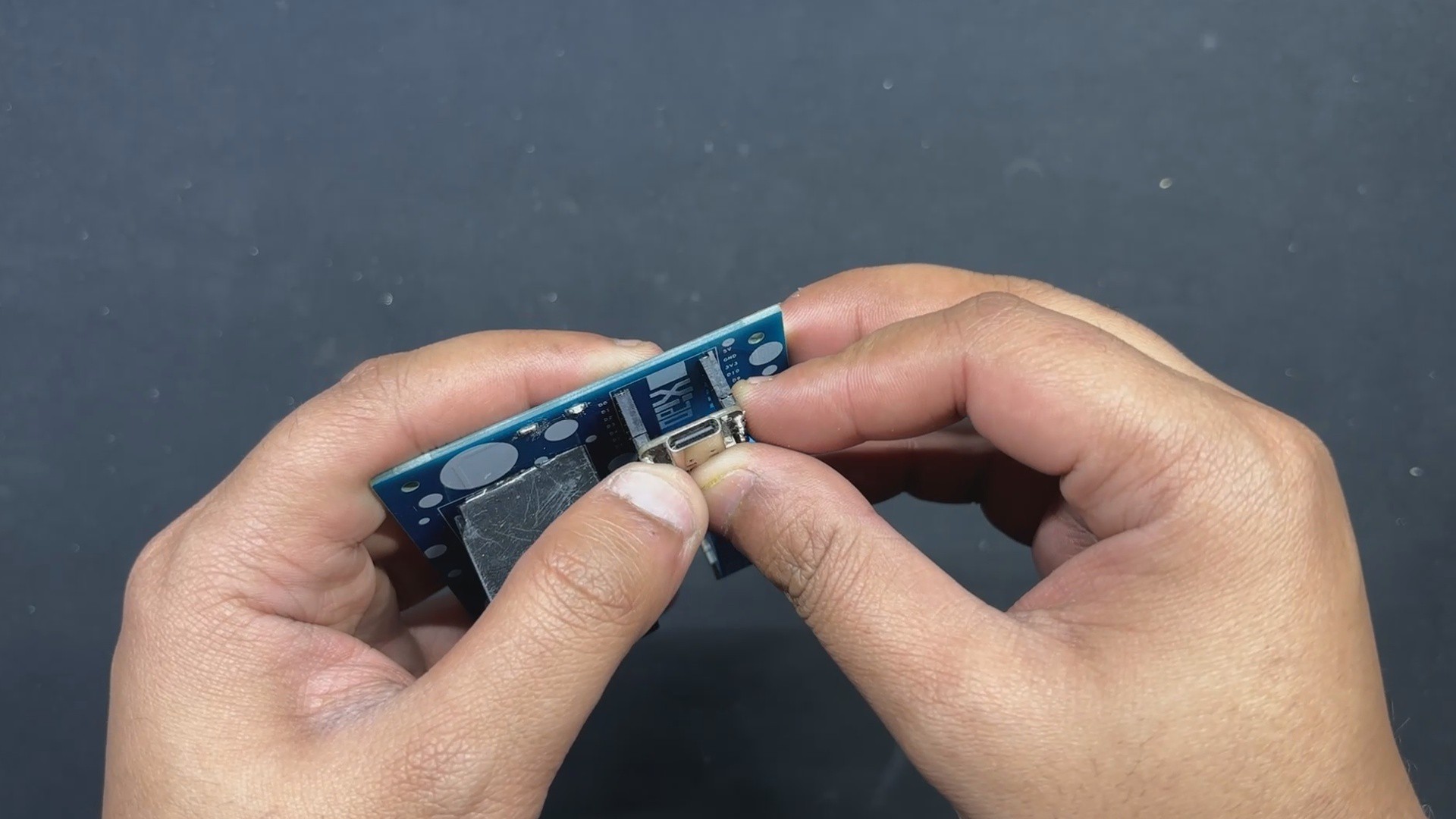
PCBs were received in a week, and their quality was super good considering the rate, which was also pretty low.
Seeed Fusion PCB Service offers one-stop prototyping for PCB manufacture and PCB assembly, and as a result, they produce superior-quality PCBs and fast turnkey PCBAs within 7 working days.
Seeed Studio Fusion PCB Assembly Service takes care of the entire fabrication process, from Seeed Studio Fusion Agile manufacturing and hardware customization to parts sourcing, assembly, and testing services, so you can be sure that they are getting a quality product.
After gauging market interest and verifying a working prototype, Seeed Propagate Service can help you bring the product to market with professional guidance and a strong network of connections.


 Andy Smith
 mulcmu
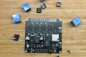
 Jon
Jon