 Mike Rigsby
The first part of the challenge was figuring out how to connect Waveshare serial servo motors to an Arduino Uno.
Some serial controlled servo motors, like the Waveshare ST3215 and Waveshare ST3025 use magnetic encoders (instead of potentiometers) to determine position. Magnetic encoders should greatly enhance reliability. In my experience with Santa's Shop, servo motors fail after 100 to 200 hours of operation--almost always due to worn potentiometers. I wrote this to assist users in controlling these serial servo motors using an Arduino Uno because I couldn't find any clear guidance for their operation.
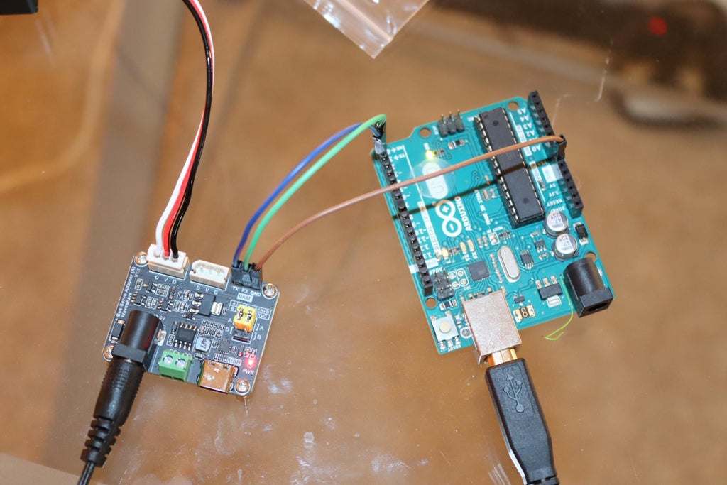
The Arduino uses two pins for serial communication, receive and transmit (pins 0 and 1). The serial servo uses one pin for both receive and transmit. Something has to give. A serial bus driver board (around ten dollars) receives the input from the Arduino and does the electrical magic necessary to talk to the servo motor.
To connect the Arduino to the bus driver board, pin 0 of the Arduino goes to "receive" on the bus driver board. Pin 1 of the Arduino Uno goes to "transmit" on the bus driver board. Ground on the Arduino goes to ground on the bus driver board. The bus driver board is powered by a 12 volt, 2 amp power supply.
Step 1: Software
There's a lot of information on the Waveshare wiki, but it's confusing and some of the code just doesn't seem to work.
First, we need to load a "library" into our Arduino programming system. In the position where we write a sketch, select "Sketch" (third from left) and click. Select "Include library," then "Manage libraries." In the box under "Library Manager," type "waveshare" and press the Enter key. Scroll down to "SCServo by FT &ws." Click "install."
We're ready to go. To control a servo (servo with ID number one, the factory default), try the code below:
#include <SCServo.h>
SMS_STS st;
#define S_RXD 0//Serial receive pins
#define S_TXD 1//Serial transmit piins
void setup() {
Serial.begin(1000000,SERIAL_8N1);
//Initializes serial port 1 communication for controlling the serial bus servo's; SERIAL_8N1 is the configuration data, parity, and stop bits; specifies the serial port pins
//Serial1.begin(1000000, SERIAL_8N1);
//Set the serial port parameter of the SCServo object to Serial1, indicating that the 1000000 serial port is used to control the servo
st.pSerial = &Serial;
delay(1000);
}
void loop()
{
st.WritePosEx(1, 4095, 3400, 50); //Set the position, speed and acceleration of servo 1 with a delay of 2s
delay(2000);
st.WritePosEx(1, 2000, 1500, 50); //Set the position, speed and acceleration of servo 1 with a delay of 2s
delay(2000);
st.WritePosEx(1, 700, 1500, 50); //Set the position, speed and acceleration of servo 1 with a delay of 2s
delay(5000);
}
Step 2: Changing Servo ID
Using the same wiring setup as before, the code below will change the servo ID Number from "1" to "9."
VERY IMPORTANT: Because this code executes one time--before starting a loop that does nothing--I find it necessary to do the following. Connect the servo to the bus board and power it up. Connect the bus board to the Arduino. Power the Arduino. PRESS THE RESET BUTTON ON THE ARDUINO (it's next to the usb connector).
I hope this helps someone use these servo motors.
#include <SCServo.h>
SMS_STS st;
int ID_ChangeFrom = 1; // Change the original servo ID, and the factory default is 1
int ID_Changeto = 9; // new ID
void setup(){
Serial.begin(1000000,SERIAL_8N1);
st.pSerial = &Serial;
while(!Serial) {}
st.unLockEprom(1); //Unlock EPROM-SAFE
st.writeByte(1, SMS_STS_ID, 9);//Change ID
st.LockEprom(9); // EPROM-SAFE is locked
}
void loop(){
}
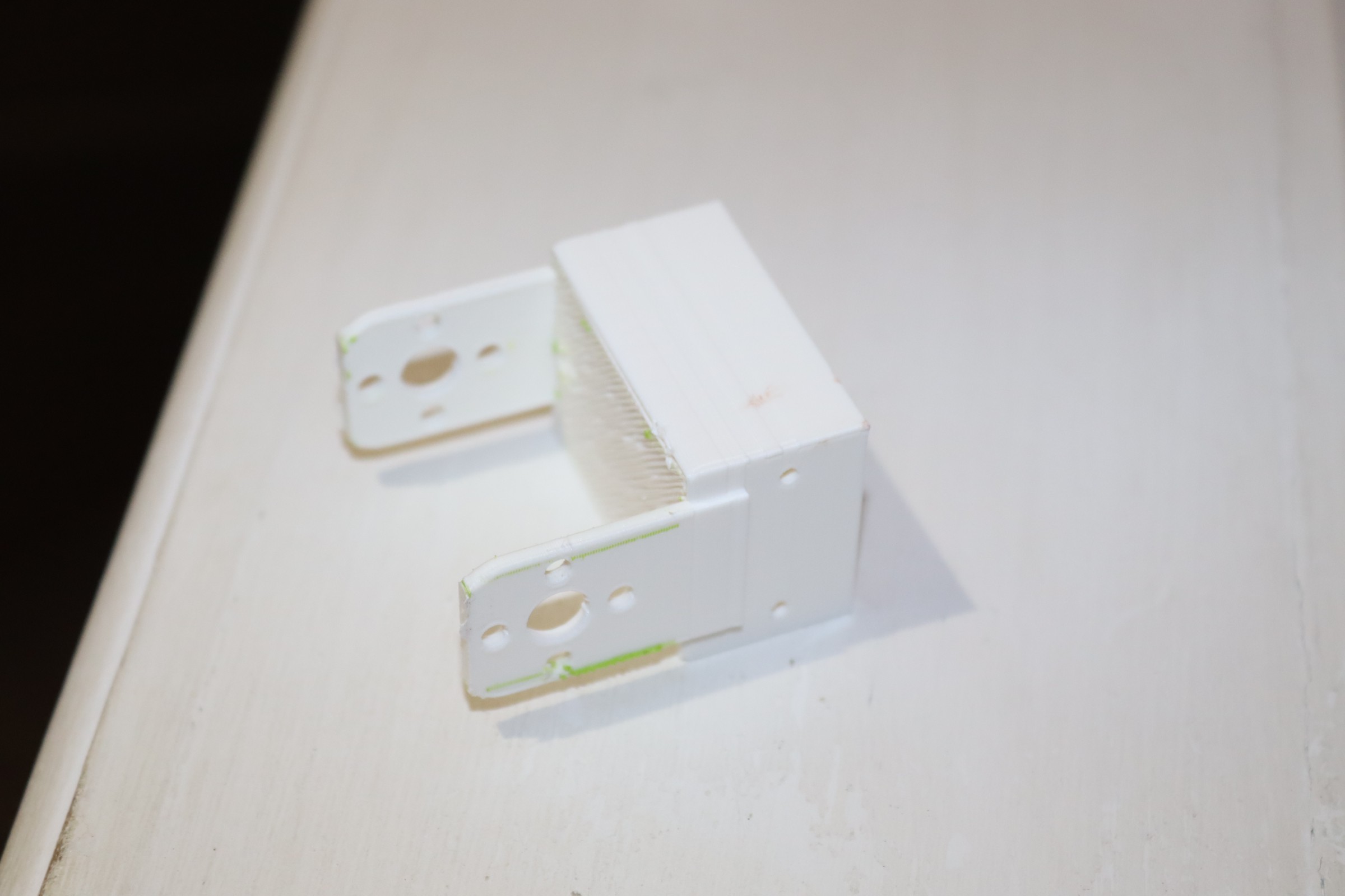
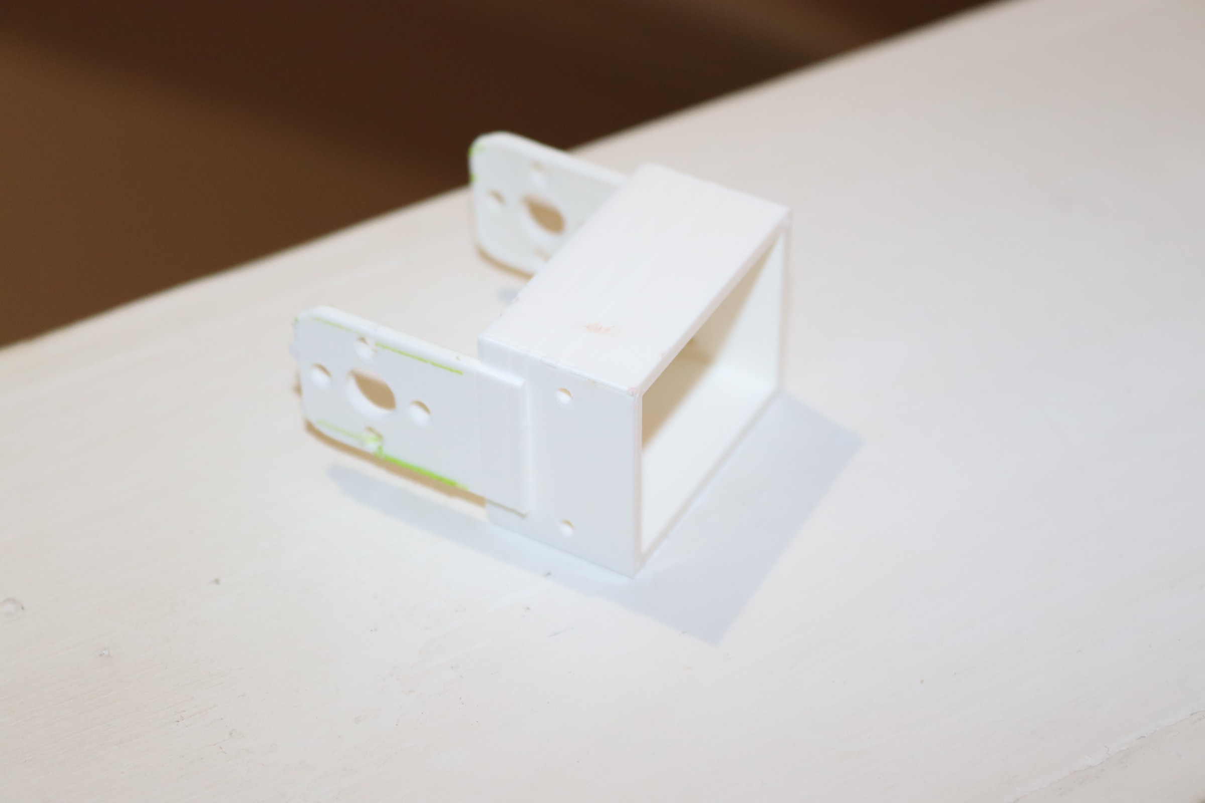
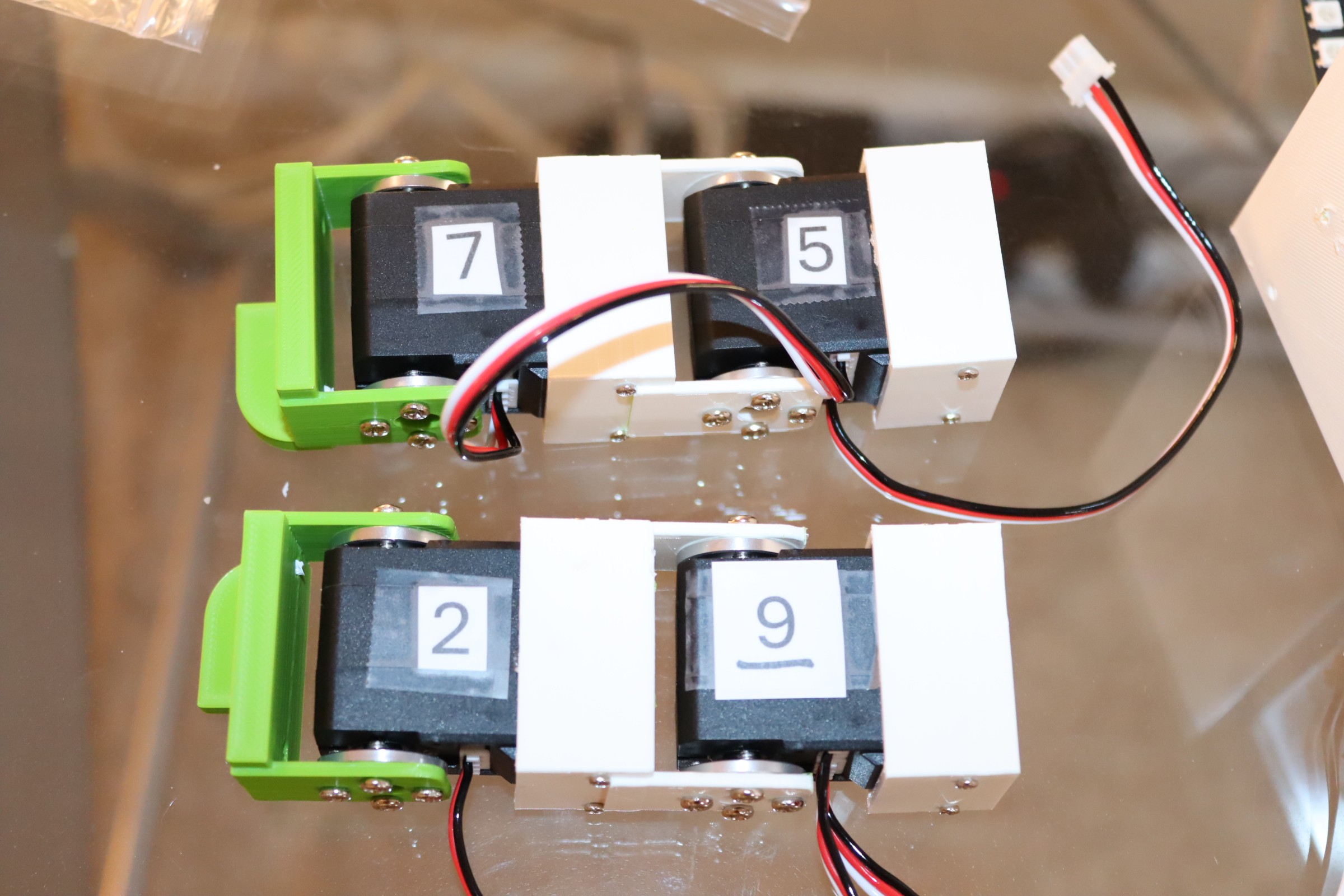
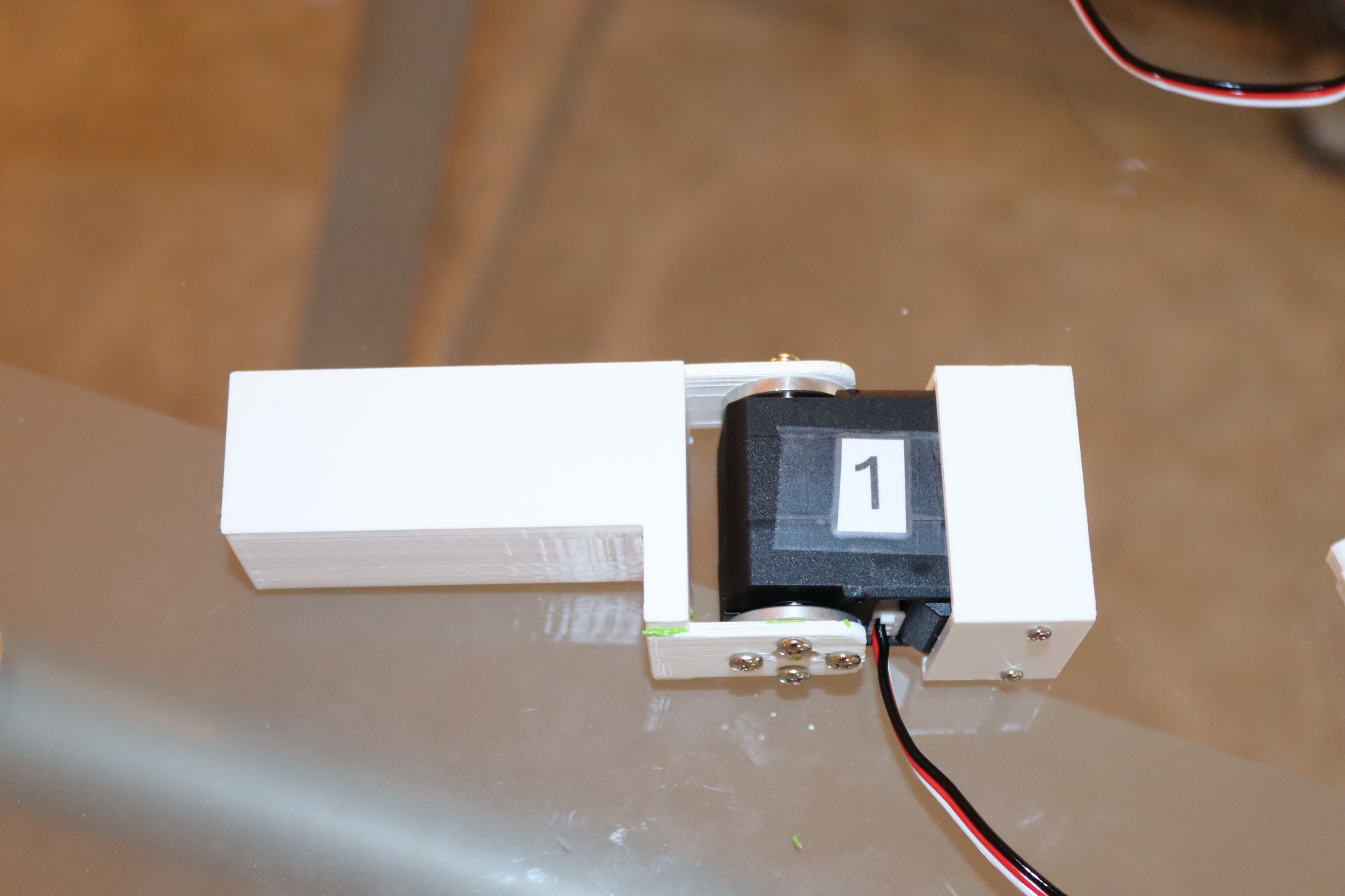
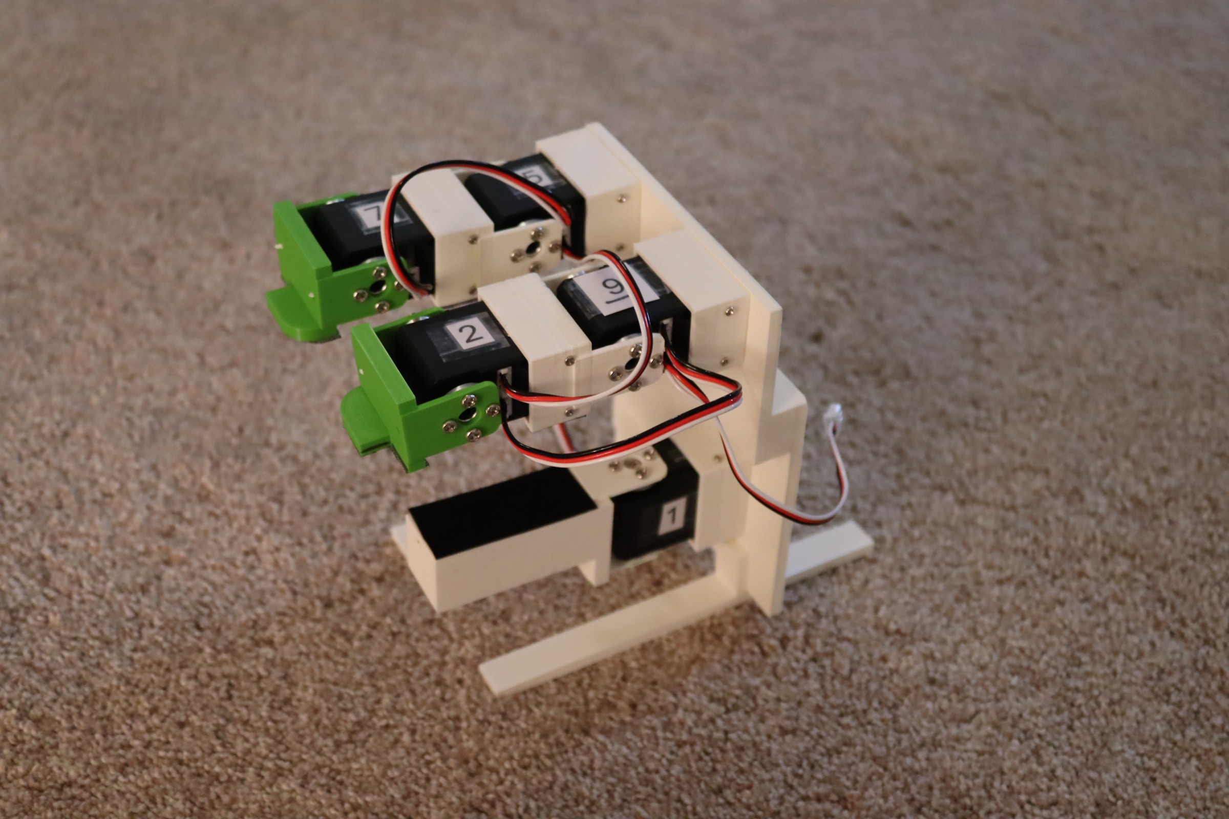
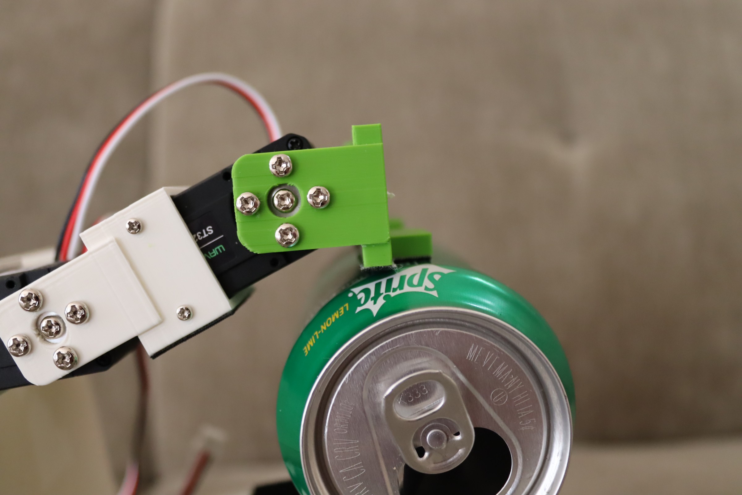
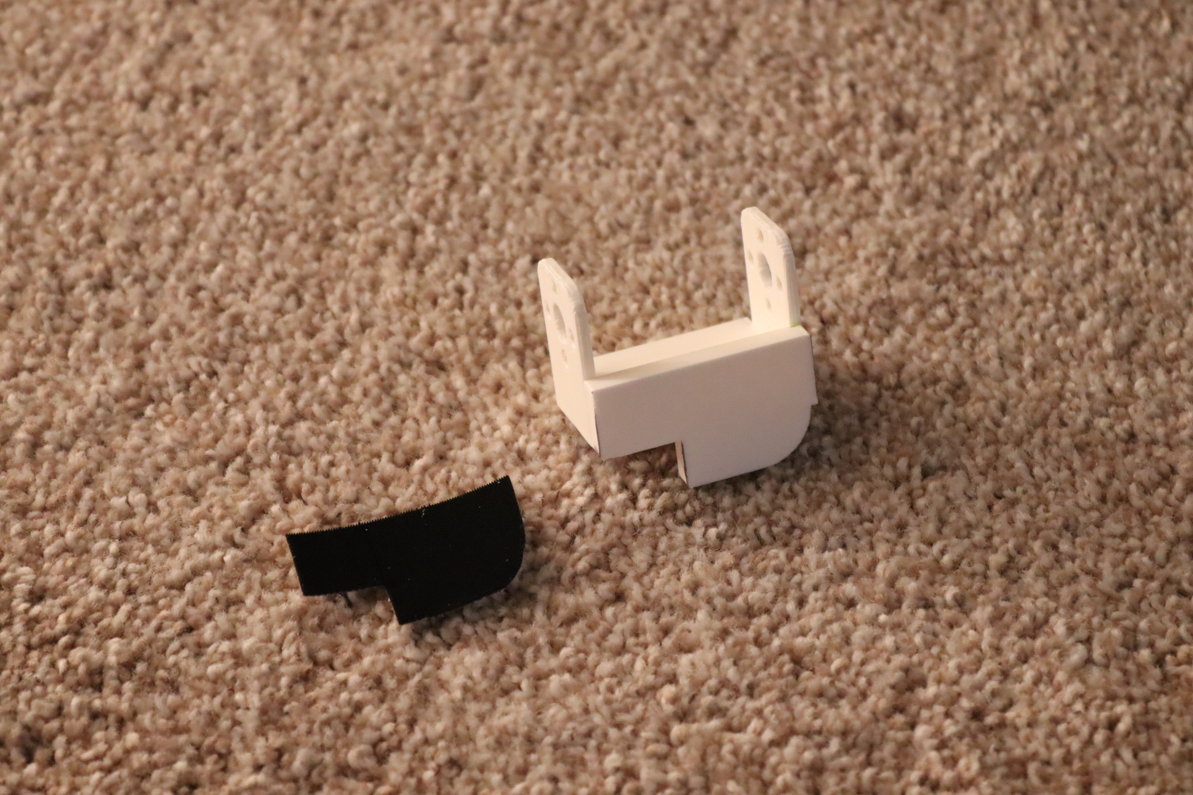
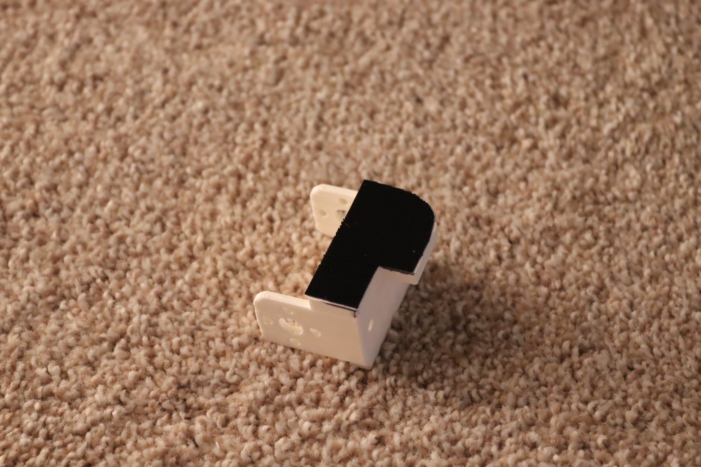
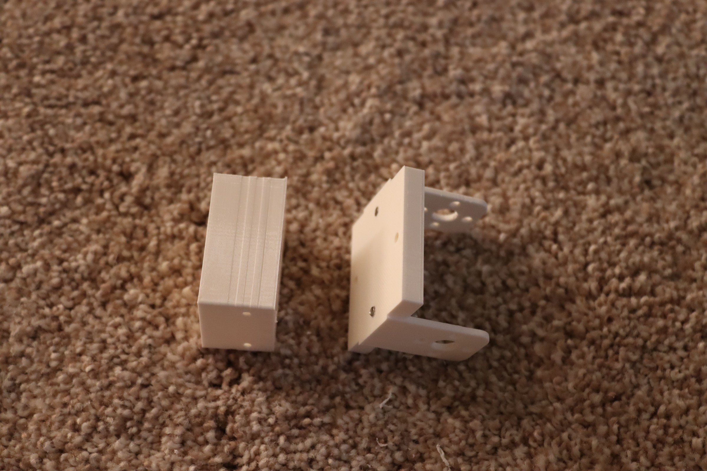
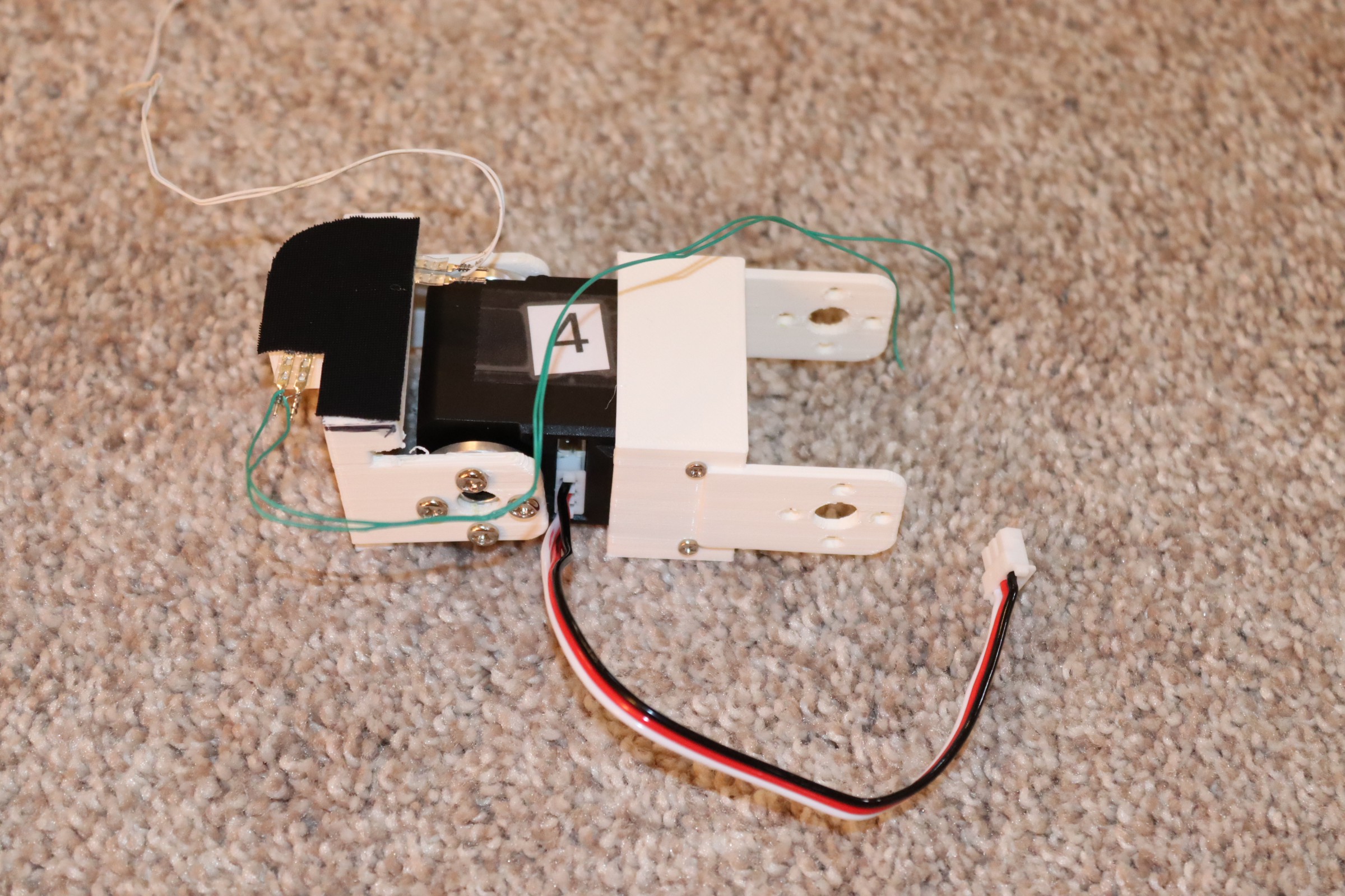
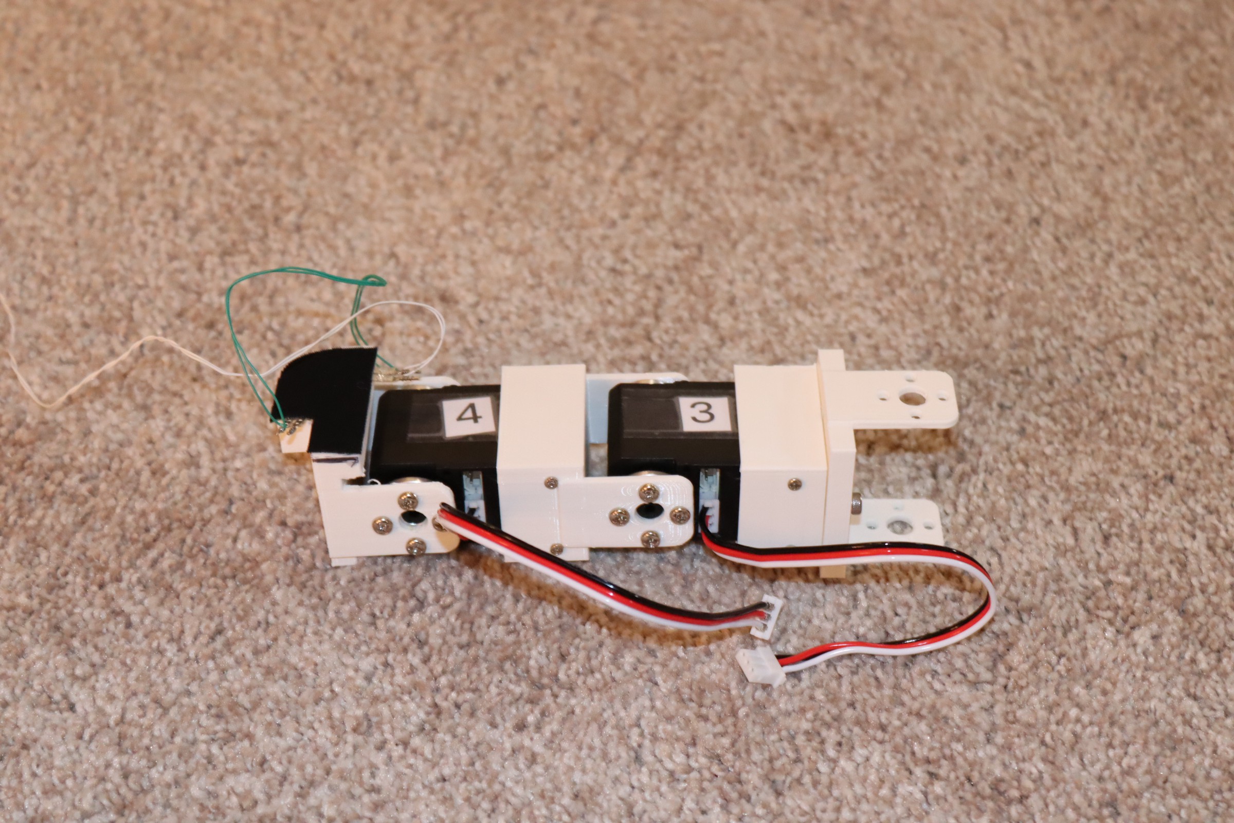
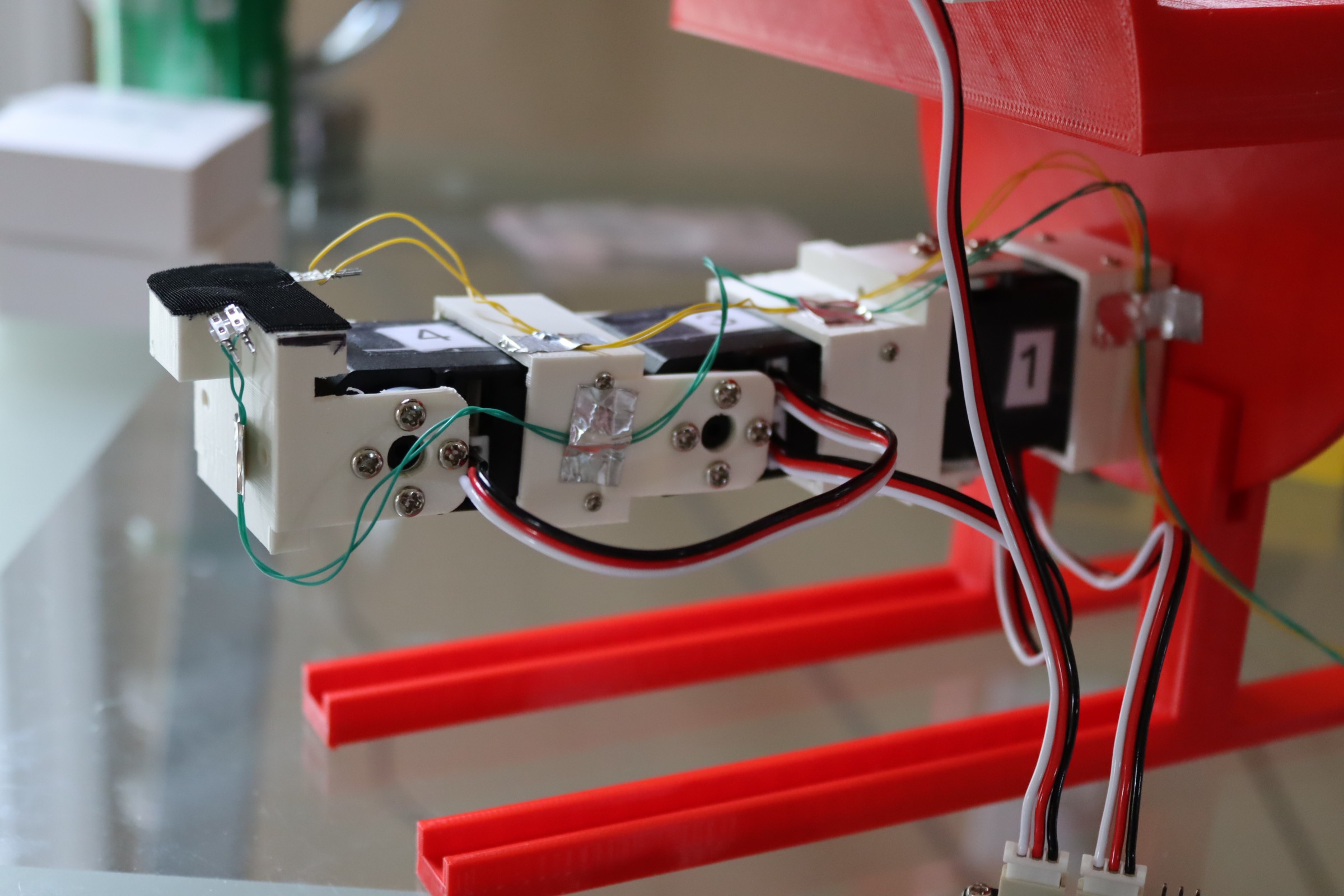
After figuring out the basics, I 3d printed a few connector pieces and assembled the hand.
K-Scale Labs can be found here. Their humanoid purchase page can be found here.
I've just started--more later.


 amr.mostaafaa
 Jeff Wahaus
 engineerkid1