dBSound Bracelet
This project aims at protecting people's hear when they are under exposure of loud noises such as a live music concert or nightclubs.
This project aims at protecting people's hear when they are under exposure of loud noises such as a live music concert or nightclubs.
To make the experience fit your profile, pick a username and tell us what interests you.
We found and based on your interests.
dBSoundBraclet.Source.inoSource Code for the projectino - 4.22 kB - 05/11/2017 at 11:21 |
|
Our final product is here. I'm happy to present you .... The dBsound Bracelet :
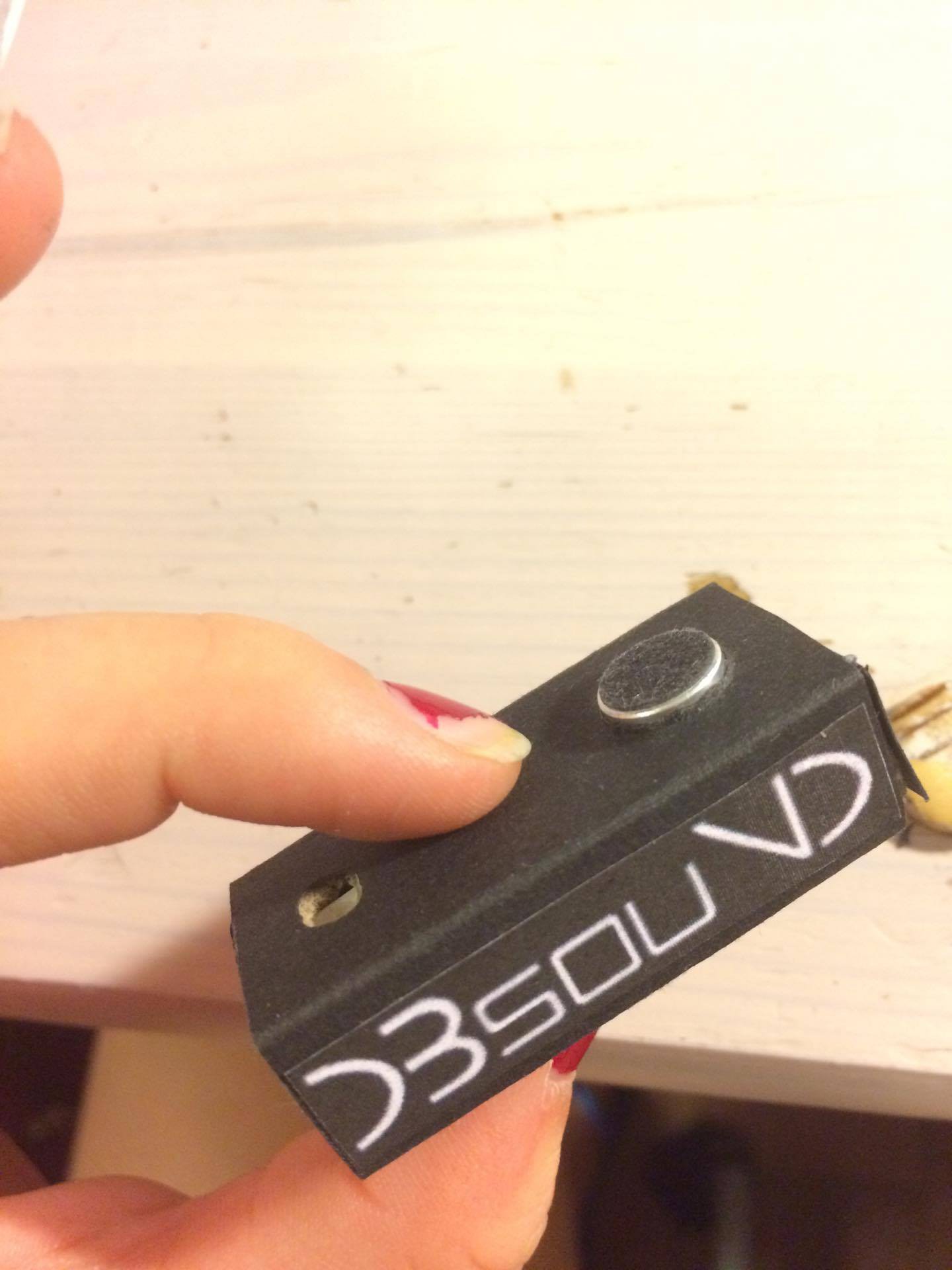
Amazing design...
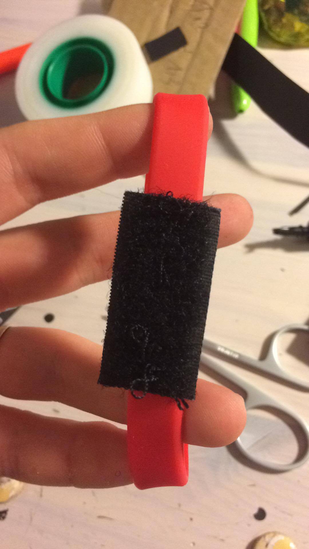
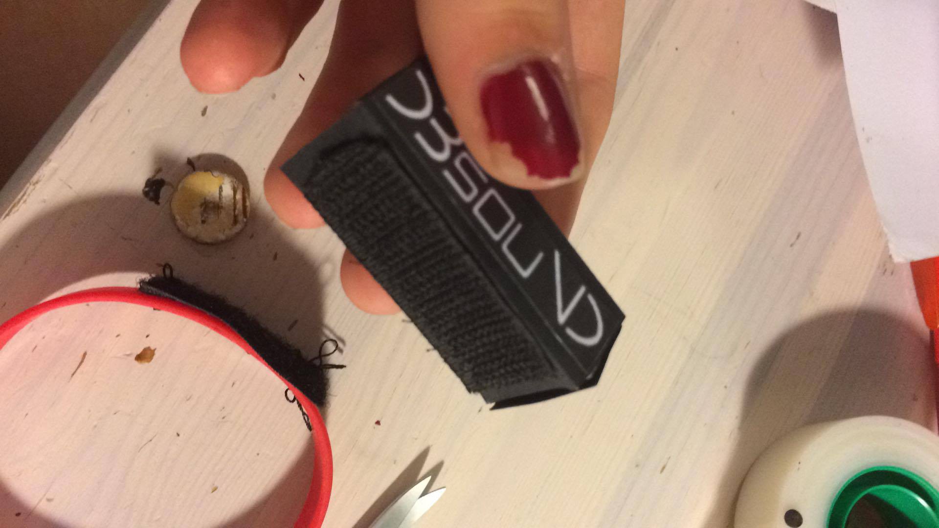
Modular...
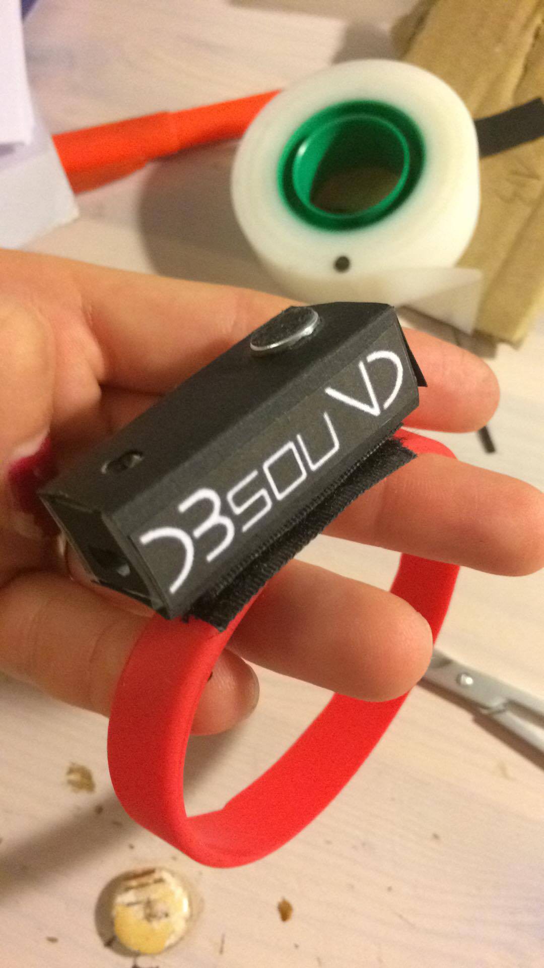
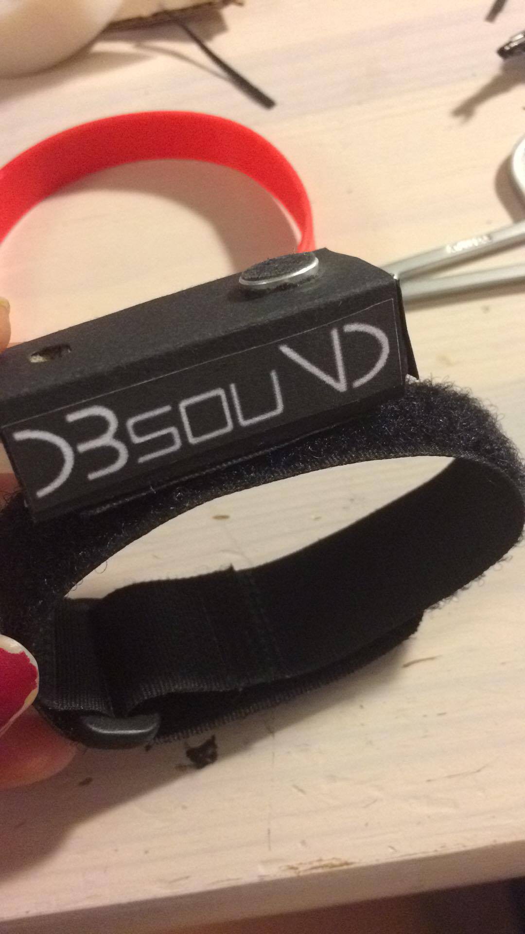
available in different colors.
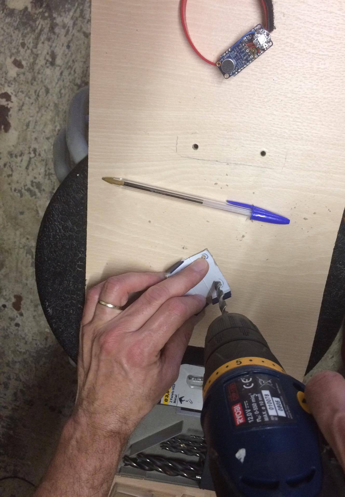
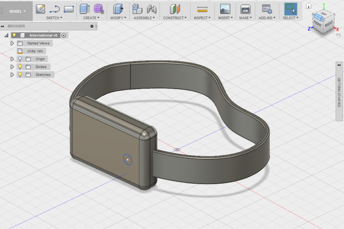
We have decided to go for a cardboard box after having some issue designing it in 3D on a software.
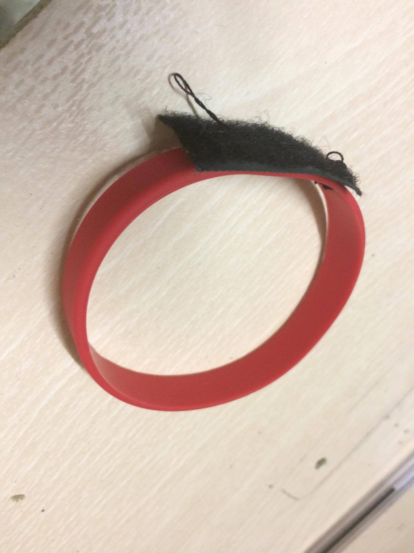
Here is how we planned to connect our box to the bracelet, with some velcro stitched to it so that the system is modulable and that the customer can choose his design
Howdy folks,
Yup we just uploaded a log yesterday but it's time for another one. Calibration was did few day ago in order to make the led blink when it should
Password for the videos : dbsound
Here is the system when the sound was loud, probably between a 100 and 120dB.
And here it is with a slighly lower volume.
You probably can't tell the difference with the iphone mic obviously but the system parameters were the same, only the volume was changed between those 2 shots.
For those who are HI-FI enthusiast here is the setup :
Celestion CS7
Sansui AU-555U
the CD is jazzmatazz vol. 1 by Guru.
Hello, everyone we thought it was time for a complete log since the two previous ones were quite small. Please, take note that that you can now find the Source Code in the shared files and that the components list has been updated too.
Let’s look at the code, I want to make sure that everyone understands it. So, I hope that it could be improved in the future.
#include <Adafruit_NeoPixel.h>
#define PIN 6
#define NUM_LEDS 1
#define BRIGHTNESS 50

Adafruit_NeoPixel strip = Adafruit_NeoPixel(NUM_LEDS, PIN, NEO_GRBW + NEO_KHZ800);

byte neopix_gamma[] = {
    0,  0,  0,  0,  0,  0,  0,  0,  0,  0,  0,  0,  0,  0,  0,  0,
    0,  0,  0,  0,  0,  0,  0,  0,  0,  0,  0,  0,  1,  1,  1,  1,
    1,  1,  1,  1,  1,  1,  1,  1,  1,  2,  2,  2,  2,  2,  2,  2,
    2,  3,  3,  3,  3,  3,  3,  3,  4,  4,  4,  4,  4,  5,  5,  5,
    5,  6,  6,  6,  6,  7,  7,  7,  7,  8,  8,  8,  9,  9,  9, 10,
   10, 10, 11, 11, 11, 12, 12, 13, 13, 13, 14, 14, 15, 15, 16, 16,
   17, 17, 18, 18, 19, 19, 20, 20, 21, 21, 22, 22, 23, 24, 24, 25,
   25, 26, 27, 27, 28, 29, 29, 30, 31, 32, 32, 33, 34, 35, 35, 36,
   37, 38, 39, 39, 40, 41, 42, 43, 44, 45, 46, 47, 48, 49, 50, 50,
   51, 52, 54, 55, 56, 57, 58, 59, 60, 61, 62, 63, 64, 66, 67, 68,
   69, 70, 72, 73, 74, 75, 77, 78, 79, 81, 82, 83, 85, 86, 87, 89,
   90, 92, 93, 95, 96, 98, 99,101,102,104,105,107,109,110,112,114,
  115,117,119,120,122,124,126,127,129,131,133,135,137,138,140,142,
  144,146,148,150,152,154,156,158,160,162,164,167,169,171,173,175,
  177,180,182,184,186,189,191,193,196,198,200,203,205,208,210,213,
  215,218,220,223,225,228,231,233,236,239,241,244,247,249,252,255 };


const int analogPin = A1; // Mic pin
int delta = 0;


void setup()
{
//Serial.begin(300);
strip.setBrightness(BRIGHTNESS);
strip.begin();
strip.show();
rainbowFade2White(3,3,1);
}

void loop()
{

int mn = 1024;
int mx = 0;


for (int i = 0; i < 500; ++i) {
int val = analogRead(analogPin);
mn = min(mn, val);
mx = max(mx, val);
}

//This is mostly used for calibration, the values don't really have to be displayed
//Serial.print("Min=");
//Serial.print(mn);
//Serial.print(" Max=");
//Serial.print(mx);
//Serial.print(" D=");
//Serial.print(mx-mn);
//Serial.println();

delta = map(mx-mn, 0, 1024, 0, 255);
//Serial.println(delta);

if(delta > 150)
  {
  colorWipe(strip.Color(255, 0, 0), 50); // Red
  colorWipe(strip.Color(0, 0, 0, 0), 50); // White
  }
else{
  colorWipe(strip.Color(0, 255, 0), 50); // Red
  }
}


void colorWipe(uint32_t c, uint8_t wait) {
  for(uint16_t i=0; i<strip.numPixels(); i++) {
    strip.setPixelColor(i, c);
    strip.show();
    delay(wait);
  }
}

void rainbowFade2White(uint8_t wait, int rainbowLoops, int whiteLoops) {
  float fadeMax = 100.0;
  int fadeVal = 0;
  uint32_t wheelVal;
  int redVal, greenVal, blueVal;

  for(int k = 0 ; k < rainbowLoops ; k ++){

    for(int j=0; j<256; j++) { // 5 cycles of all colors on wheel

      for(int i=0; i< strip.numPixels(); i++) {

        wheelVal = Wheel(((i * 256 / strip.numPixels()) + j) & 255);

        redVal = red(wheelVal) * float(fadeVal/fadeMax);
        greenVal = green(wheelVal) * float(fadeVal/fadeMax);
        blueVal = blue(wheelVal) * float(fadeVal/fadeMax);

        strip.setPixelColor( i, strip.Color( redVal, greenVal, blueVal ) );

      }

      if(k == 0 && fadeVal < fadeMax-1) {
          fadeVal++;
      }

      else if(k == rainbowLoops - 1 && j > 255 - fadeMax ){
          fadeVal--;
      }

        strip.show();
        delay(wait);
    }
  }
  delay(500);
  for(int k = 0 ; k < whiteLoops ; k ++){
    for(int j = 0; j < 256 ; j++){
        for(uint16_t i=0; i < strip.numPixels(); i++) {
            strip.setPixelColor(i, strip.Color(0,0,0, neopix_gamma[j] ) );
          }
          strip.show();
        }
        delay(2000);
    for(int j = 255; j >= 0 ; j--){
        for(uint16_t i=0; i < strip.numPixels(); i++) {
            strip.setPixelColor(i, strip.Color(0,0,0, neopix_gamma[j] ) );
          }
          strip.show();
        }
  }
  delay(500);
}


uint32_t Wheel(byte WheelPos) {
  WheelPos = 255 - WheelPos;
  if(WheelPos < 85) {
    return strip.Color(255 - WheelPos * 3, 0, WheelPos * 3,0);
  }
  if(WheelPos < 170) {
    WheelPos -= 85;
    return strip.Color(0, WheelPos * 3, 255 - WheelPos * 3,0);
  }
  WheelPos -= 170;
  return strip.Color(WheelPos * 3, 255 - WheelPos...
Read more »
Yay !
We had the pleasure to meet our new test-subjects this morning. They all looks ready to do some hard work, wich is great (ofc it is). Let's soulder a bit and improve the code, it should be finished soon tho - a log we'll be posted to keep you in track. 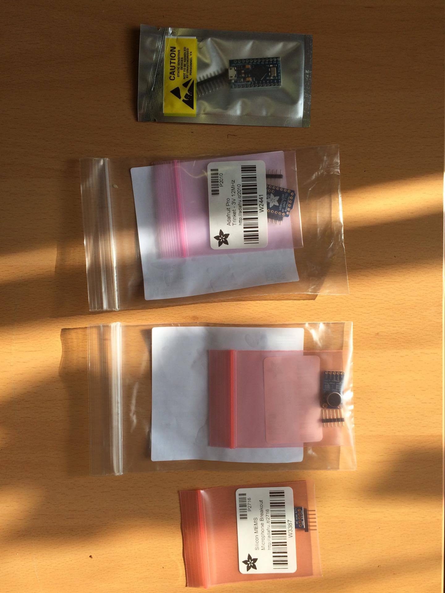
Here is an idea of design for the integration of the component on the bracelet that came today. Not sure what we'll do next, but an idea is idea. It should be considered and not thrown away, even if it looks like abstract art.
See you soon fellas !
We tried some stuff today, didn't really worked as expected. However, we found a way to mesure a sound level in a "decent" way.
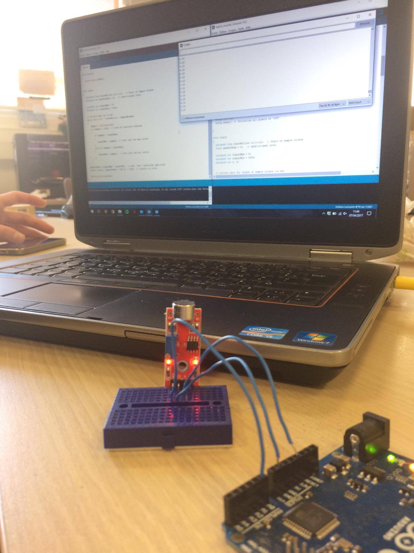 Our components haven't been received by the CRI yet, so we were just working on some spare components.
In the meantime Claire & Nicolas are working on the deseign. The objective is clearly to make it as attractive as possible. It should be a pleasure to wear it.
Hey everyone,
We've made a bunch of things today, let's take a look.
The component list was updated today (03/24/2017) here are some explanations about what you need to create this project at home. Please note that all the components are still on a test phase and won't all be used. This list will obviously be updated so stay tuned folks !
Both were chosen because of their size, they'll make easier the final integration on the bracelet. However they are still very powerful and can be almost coded like a classic arduino. The main difference between the Pro Trinket and the Trinket Mini is the size, and so the CPU attached on those. Maybe the mini specs (ATtiny85, 8K of flash, 512 byte of SRAM, 512 bytes of EEPROM) will be a bit low, but we will see in a few weeks !
Several ones were chosen, because we are afraid of saturation and resolution. We don't want the mic to be saturated at 100dB for example. It would be a shame because we want to detect the sound up to 130dB at least. The MAX4466 is quite classical and has an integrated op-AMP and gain can change from 25x to 125x while the MAX9814 has an automatic gain control. However "max gain" can obviously me modified. Finally the SPW2430 is the smaller one and probably the best for audio detection while the two previous ones can be used for recording/sampling - but "the output peak-to-peak voltage has a 0.67V DC bias and about 100mVpp" - so it's the more likly to clip/sature on high-level sounds. So at this point we don't have any favorites !
First of all we wanted super tiny and basic leds but then we moved to adafruit's Neopixels. They are way much bigger than what we looked at the beginning but they are also way much cooler because you can change color and use a Bus to control them, it means less wiring and we love that !
Feel free to take a look at our schedule, so you won't miss any updates. They'll be mostly posted every wednesday, when we are at the CRI Paris, France.

Bertrand started working on the code, he'll use or at least fin inspiration on the following one wich was created by adafruit (them, again). It's quite close from what we're trying to do, but in a different way and with different objectives (however this is a rad tie).
Adafruit related project : https://learn.adafruit.com/led-ampli-tie/overview
Here is the raw code (our's will be a lot easier)
Read more »Hello everyone and welcome !
Make yourself home and take some times to discover our project. So far we don't have a lot of things to tell you. At least no more that you could find in the description of the project. Or maybe one little thing : we're searching for components (interesting uh). It's indeed a little bit boring, but it's a proof that the project is really starting - and yes, this is exciting !
See you soon !

Create an account to leave a comment. Already have an account? Log In.
Agree with the analog design! Could a low pass filter be enogh? I'very heard that some frequencies are more dangerous than others, in this case adc + sampling could be required, and this part you've already done :)
Become a member to follow this project and never miss any updates
 Sagar 001
 Paulson K Antony
 Drap & Design
 Floz
Floz
Also done most of this on a microcontroller in my project from last year. The weak part is the AVR, ADC, sampling rate, resolution and Arduino framework. Could be a lot easier doing this all in analog with opamp/comparator.
It has input DC offset, level and some loudness detection in real time signal processing code.
https://hackaday.io/project/12133-automatic-audio-source-switching
This has microphone input analog design.
https://hackaday.io/project/12703-alarm-detection-for-hearing-impaired