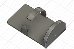
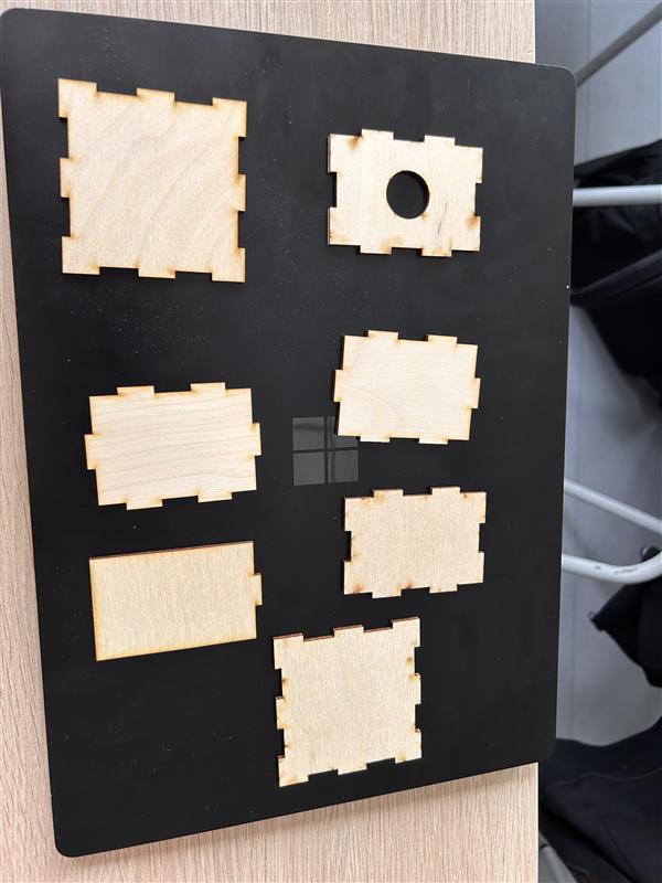
While the cylinder itself will be exposed to very little stress, the gearing will face considerably more
Due to expected stresses exerted upon the driving gear and those dedicated to the governor, it would seem they will need to be metallic or otherwise sturdier than a simple 3D printing
For that reason, we will need to look at using standardized parts in order to simplify the building process
The purpose of the governor in the system is to ensure a stable speed of the cylinder
It accomplishes this goal by increasing its rotational inertia the faster the device is turning
It does so by having a pair of mobile counterweight that get higher and further from the axle as the rotation speed increase
We will be using a version of the mechanism called the Watt Governor
This version is fully passive, with no tuning component beyond the mass of the counterweights
For our purpose, the ideal situation would be a rotation speed between 150 and 200 rpm with counterweight somewhere between 15 and 20 grams per counterweight
The user is deemed to spin the handle between 60 and 120 rpm
With the current gear shaft, this means the driving gear will go from 12 to 24 rpm
In order to reach our operating rotational speed, we need to have a gear ratio in the neighborhood of 15 between the driving gear and the governor.
Recived the kalimba. We worked with fusion 360°to upload the kalimba into the program then we measured the, angles, and size of the cylinder to fit the kalimba and the tines(notes).