Close
0%
0%

PICO TEMPERATURE GUN Version 1

Raspberry Pi PICO 2 Powered TEMP GUN based around the GY-906 Infrared Temp Module.

Similar projects worth following
0 followers
Greetings everyone and welcome back. Here's something useful.

The PICO TEMPERATURE GUN Project is a do-it-yourself temperature gun project that uses the PICO 2 and the GY-906 Infrared Temperature Sensor to take temperature readings and display them on an SSD1306 124x32 OLED screen.
The goal was to create an open-source, functional temperature gun from scratch using a PICO 2 and GY-906 (MLX90614), a non-contact infrared temperature sensor with a high precision of ±0.5°C.

It provides two output modes: PWM (pulse width modulation) and SMBus (I2C). The 10-bit PWM output has a resolution of 0.14°C, whereas the I2C interface has a resolution of 0.02°C. We are now using the I2C mode.

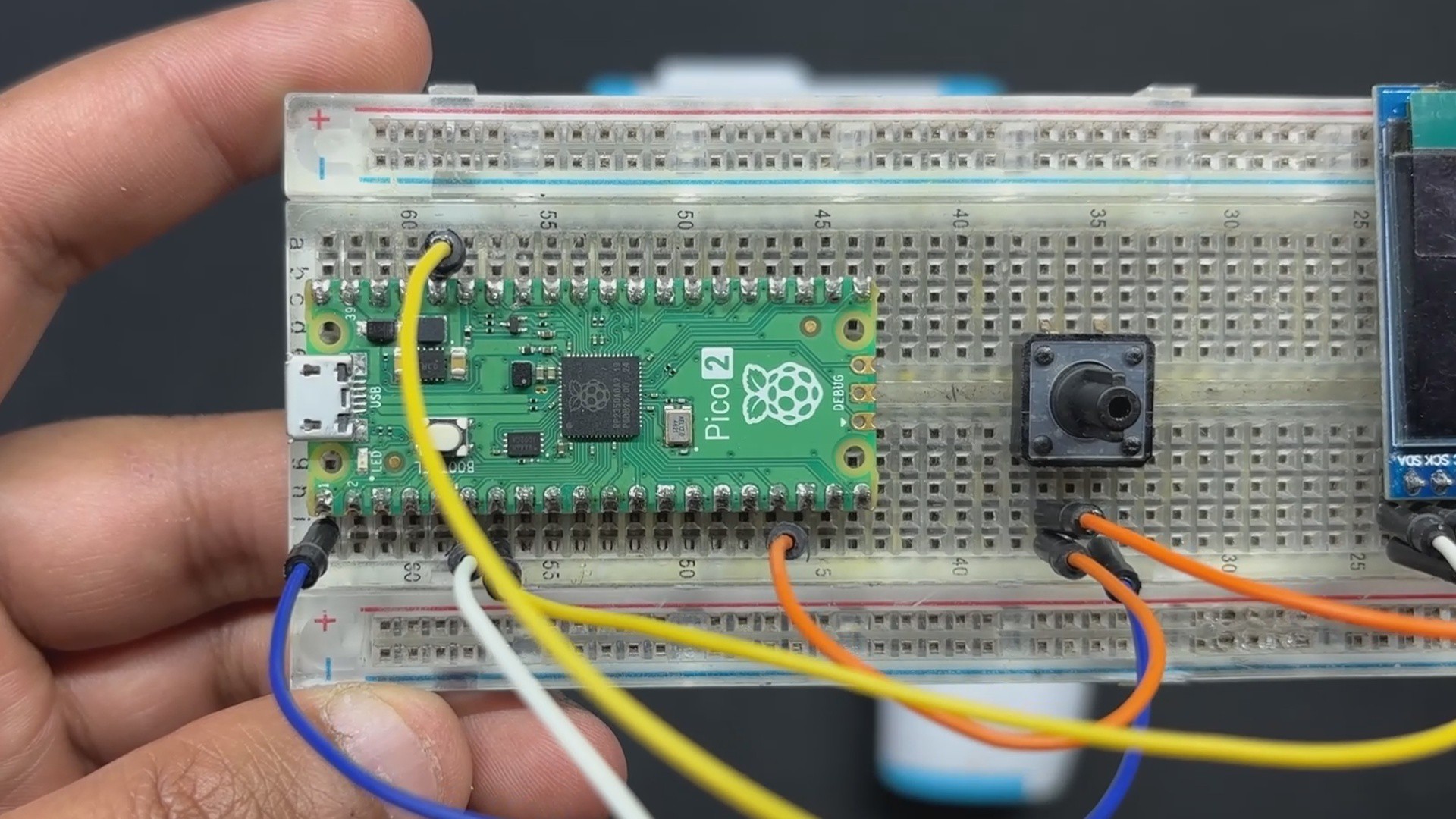
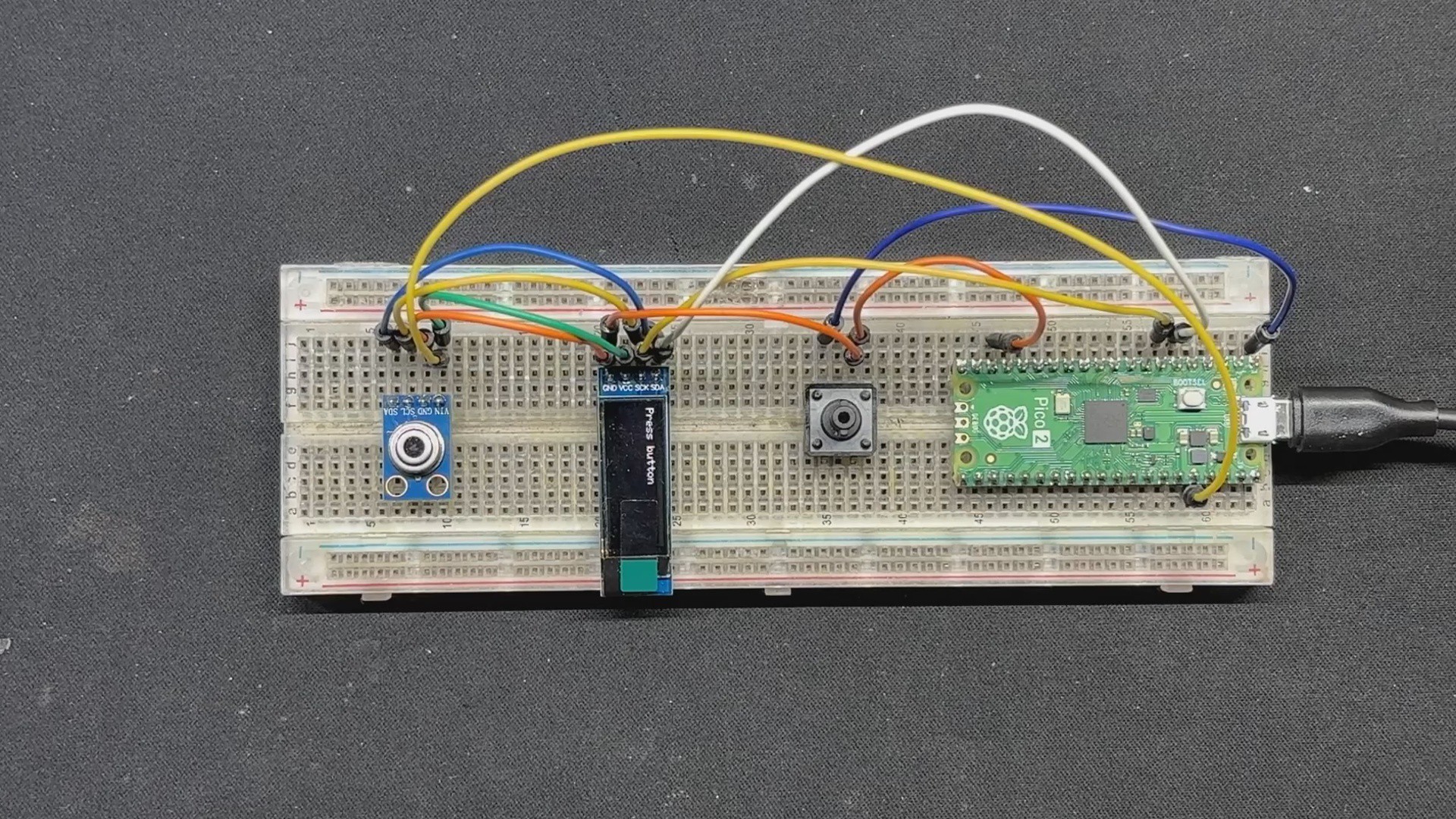
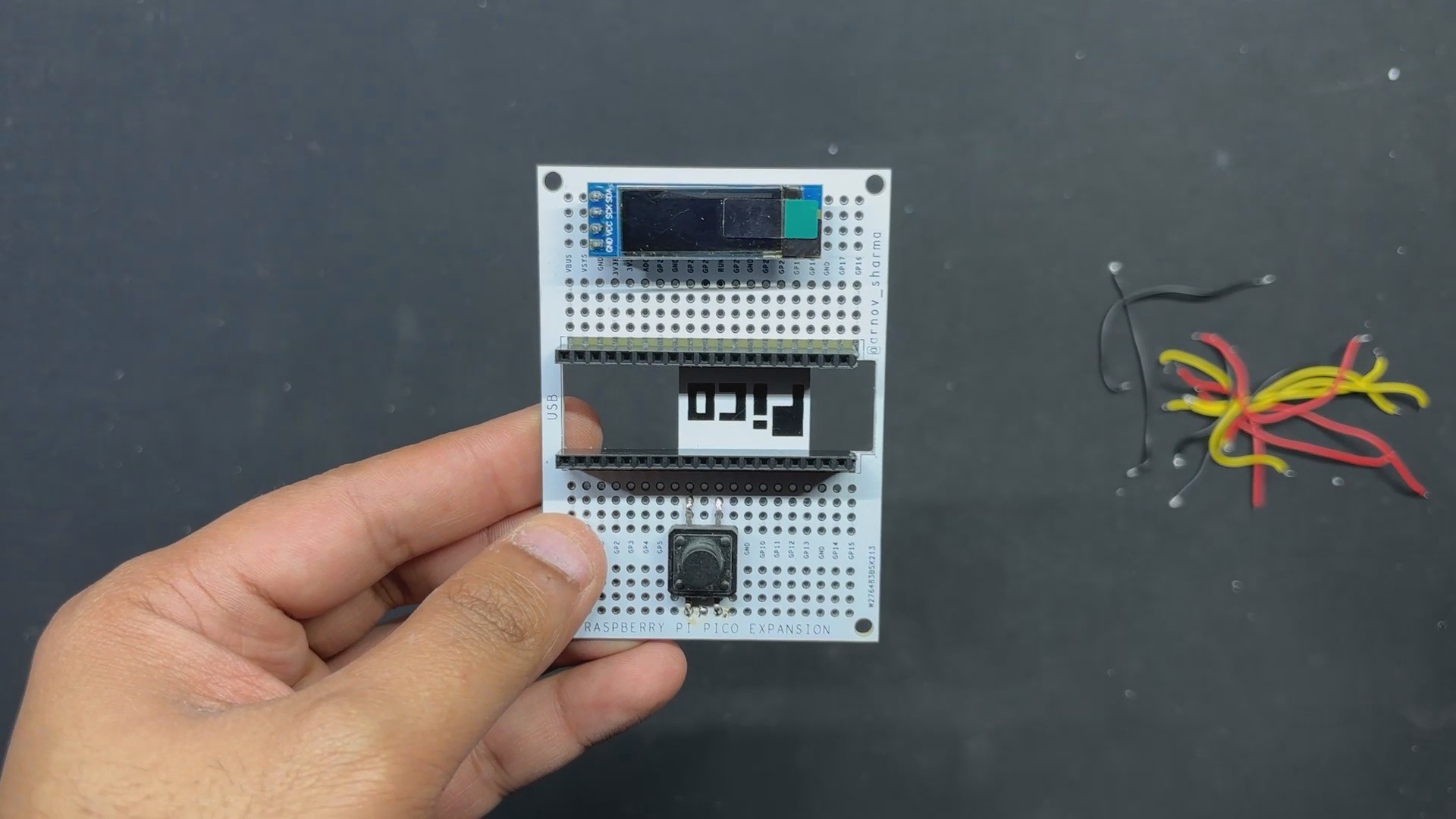
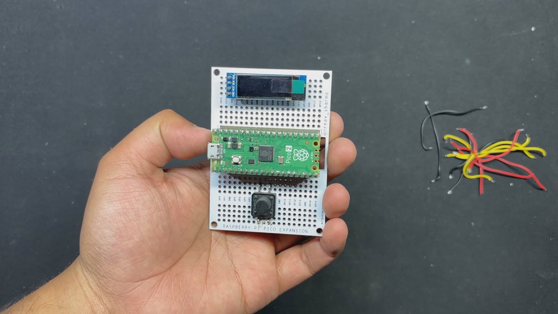
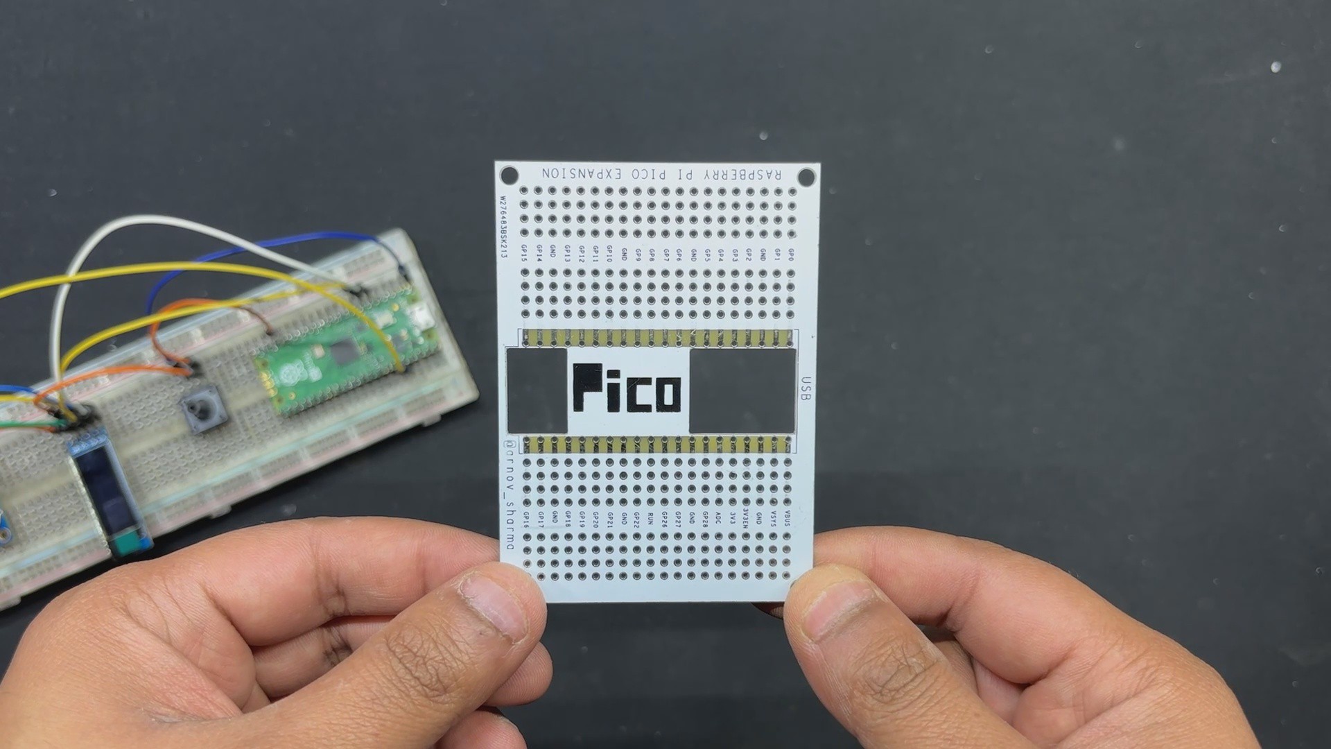
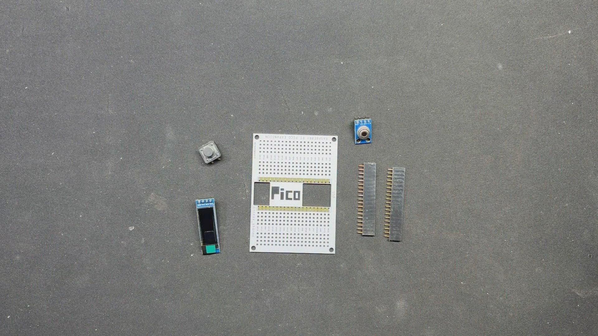
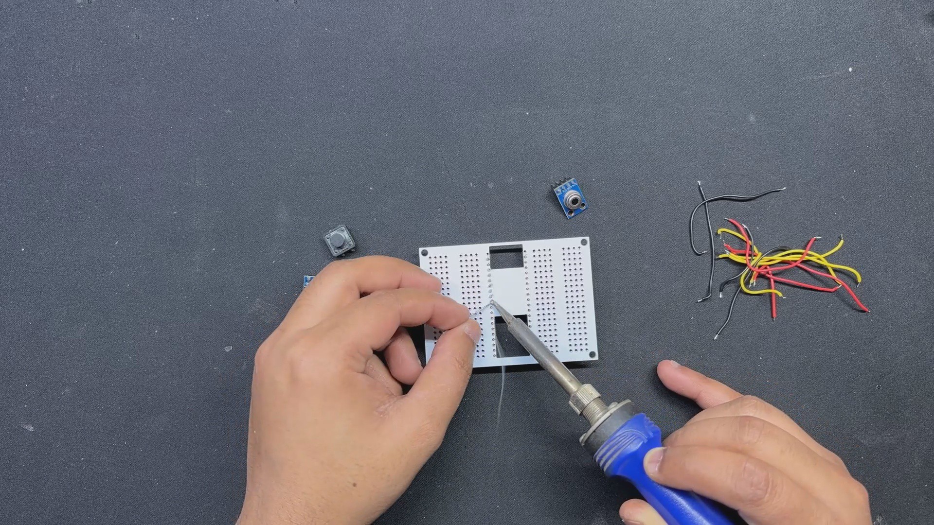
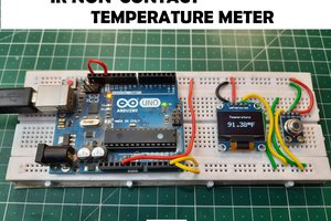
For this project, we created two variants: a breadboard version for simple setup and a prototype PCB version that links all components on a beautiful PCB, making the entire setup easier and more practical to use.

For Version 2 of this project, we will design a customized PCB with a temperature gun-style enclosure as housing and an onboard battery pack.

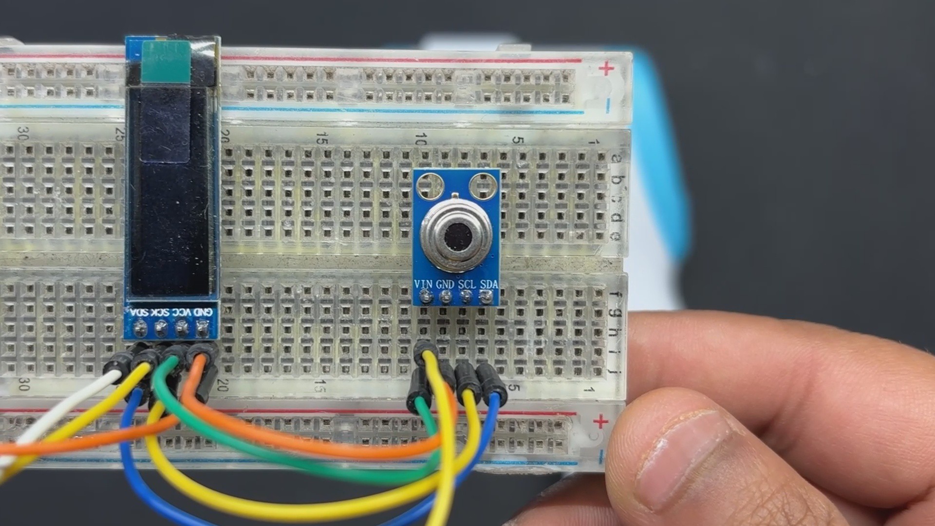
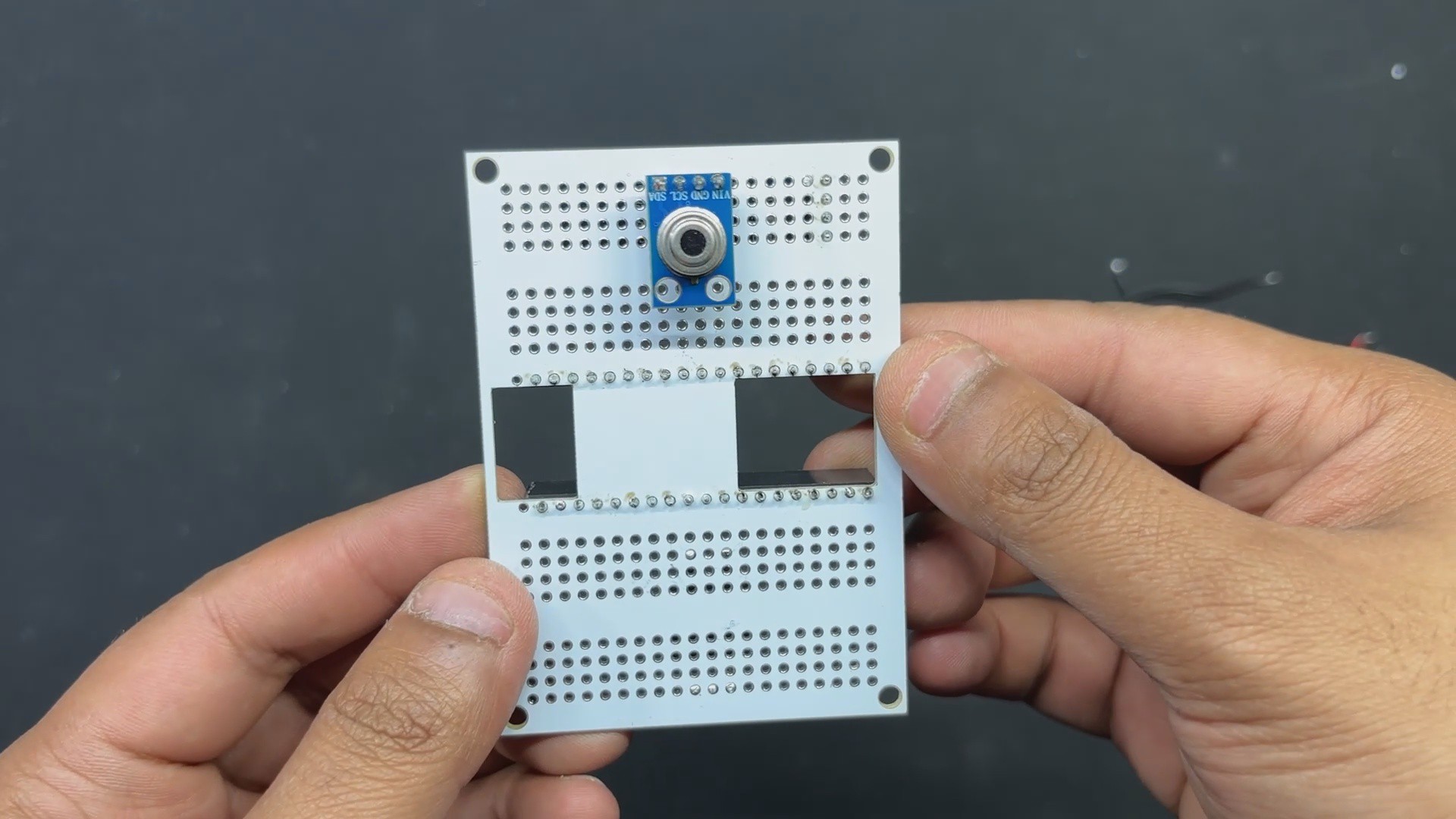
GY-906 Infrared Temperature Sensor Module

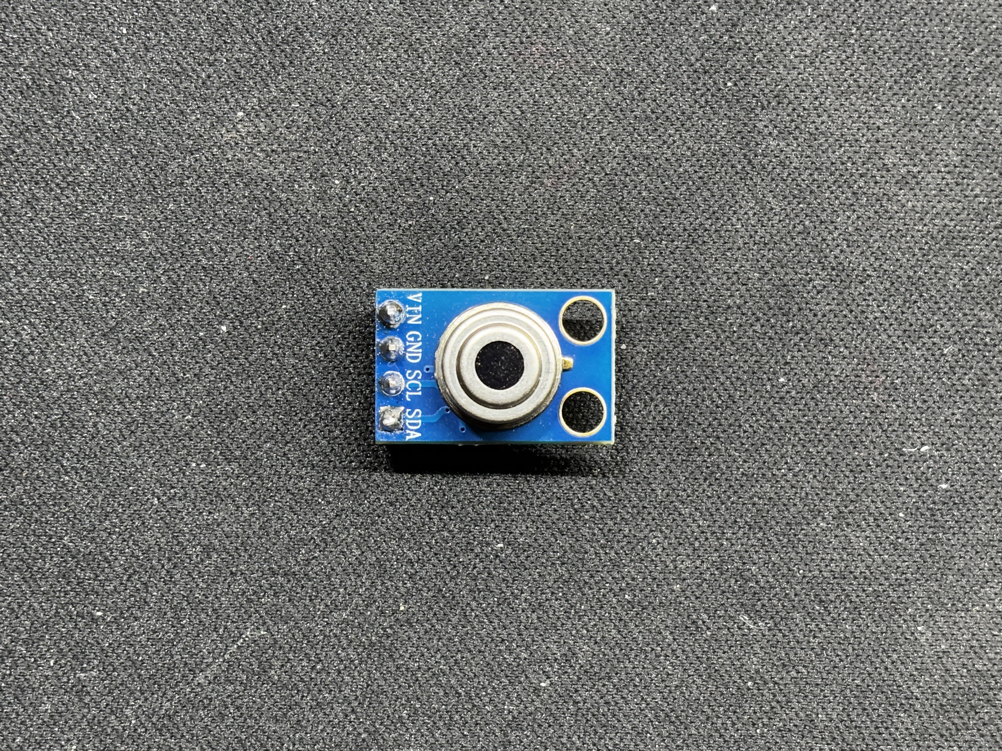
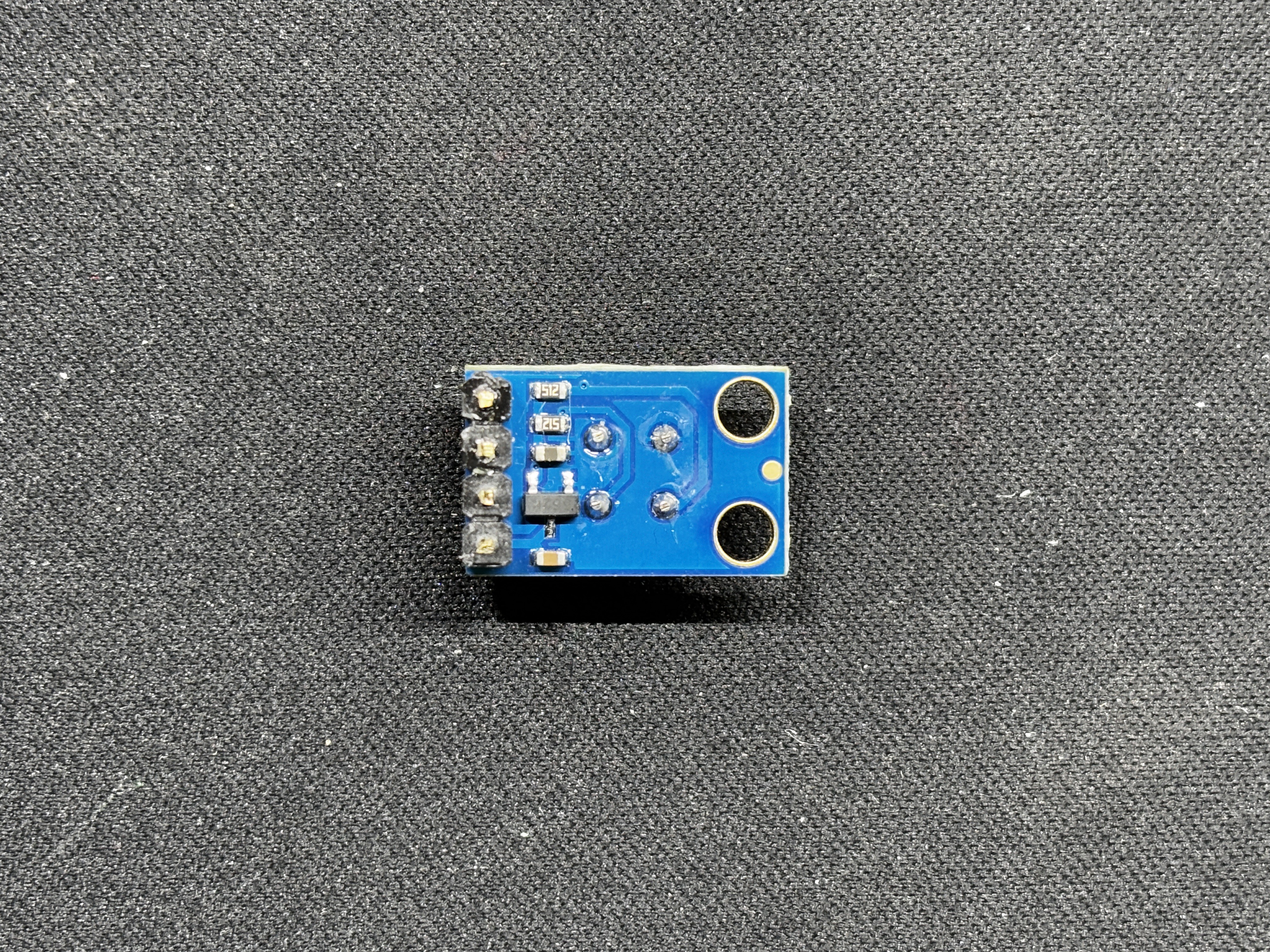
The GY-906 (MLX90614) infrared temperature sensor is a very precise and adaptable device that is commonly used for non-contact temperature readings. It functions over a wide temperature range, from -70°C to +380°C for objects and -40°C to +125°C for the sensor.

The sensor is highly precise, with a resolution of 0.02°C and an accuracy of ±0.5°C about ambient temperature.

The sensor's dual output techniques (PWM and I2C) allow for versatility in a variety of applications. Users can obtain 0.14°C and 0.02°C resolutions using a 10-bit PWM output and an I2C interface.

It can perform properly with voltages ranging from 3.3V to 5V.

This sensor employs infrared technology to determine the temperature of a surface without making physical contact. This is especially beneficial in instances where direct contact is not an option, such as moving items, sensitive surfaces, or hazardous compounds.

Fun fact: during COVID, these sensors were commonly utilized to manufacture temperature guns.

All objects emit infrared light as a function of temperature. An infrared temperature sensor detects the infrared radiation emitted by an object, converts it to a voltage, processes this signal to calculate the temperature, and then communicates this information to a microcontroller via the I2C interface.

This non-contact approach enables accurate and reliable temperature measurements without requiring physical touch with the object being measured.

PCBWAY Giftshop

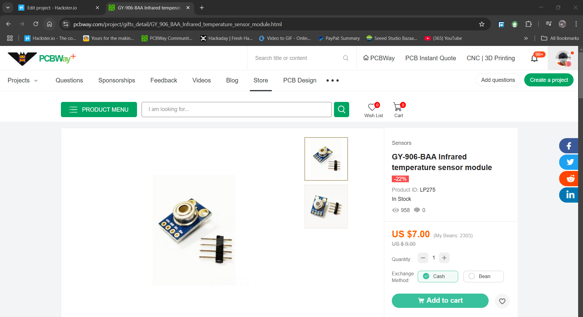
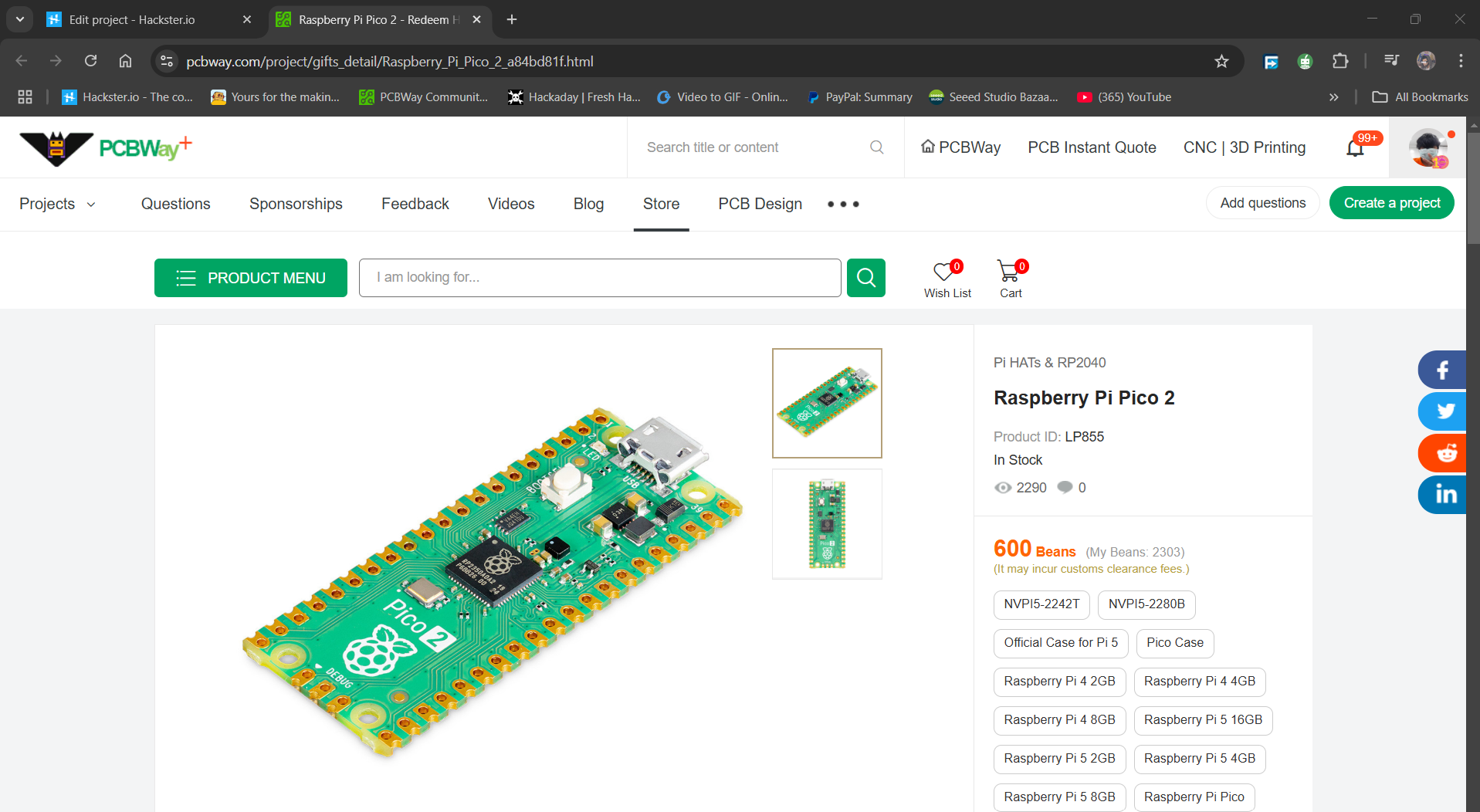
As for sourcing the GY906 temperature sensor along with PICO 2 we used in this project, we got them from PCBWAY's Giftshop.

https://pcbway.com/s/D3237G

https://pcbway.com/s/S01elv

PCBWAY gift shop is an online marketplace where you can get a variety of electronics modules and boards for their genuine price, or you could use the PCBWAY currency, which is called beans.

You get beans after ordering something from PCBWAY as reward points, or you can also get them by posting any project in the PCBWAY community.

Also, PCBWAY is organizing a PCB badge-making competition to mark their 11th anniversary, inviting designers and makers to showcase their creativity by designing badges that celebrate the company's legacy and envision a bold future. Participants must incorporate the elements "PCBWay" and the number "11" in their designs and can use PCB, PCB+SMT/THT, or PCB+3D printing techniques. Submissions can be posted in the comments, emailed, or shared on social media with the hashtag #PCBWay11BadgeContest.

Prizes include cash, PCBway coupons, and free prototyping services for all qualifying entries.

You guys can check out PCBWAY if you want great PCB service at an affordable rate.
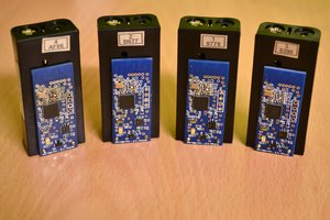
  • 1
    Breadboard Version

    We begin the project by setting up the breadboard version. We start by placing all four components on the breadboard: the PICO 2, switch, OLED screen, and temperature sensor.

    Next, we connect the GND of the PICO to the switch 1 input; the GND of the OLED screen is likewise linked to the GND of the PICO and the temperature sensor.

    We next connect the VCC of the display and temperature sensor to the PICO's 5V supply.

    The button's second terminal is connected to GPIO0 next.

    Now, we connect PICO's I2C, GPIO4 (SDA) and GPIO5 (SCL), to the SDA and SCL pins of the display and temperature sensor in parallel.

    After connecting the wires, we input the main code into the device, which only displays the current temperature measured by the temperature sensor when the button is pressed.

  • 2
    CODE

    Here's the code for this project and its a simple one.

    #include <Wire.h>
    #include <Adafruit_GFX.h>
    #include <Adafruit_SSD1306.h>
    
    #define SCREEN_WIDTH 128
    #define SCREEN_HEIGHT 32
    #define OLED_RESET    -1
    Adafruit_SSD1306 display(SCREEN_WIDTH, SCREEN_HEIGHT, &Wire, OLED_RESET);
    
    const int buttonPin = 0; // GPIO0 pin for button
    const int sensorAddress = 0x5A; // GY-906-BAA I2C address
    
    void setup() {
      Serial.begin(9600);
      pinMode(buttonPin, INPUT_PULLUP);
      Wire.begin();
    
      // SSD1306 OLED display initialization
      if (!display.begin(SSD1306_SWITCHCAPVCC, 0x3C)) {
        Serial.println(F("SSD1306 allocation failed"));
        for(;;);
      }
      display.display();
      delay(2000); // Pause for 2 seconds
      display.clearDisplay();
      display.setTextSize(1);
      display.setTextColor(SSD1306_WHITE);
      display.setCursor(0, 0);
      display.print("Press button");
      display.display();
    }
    
    void loop() {
      int buttonState = digitalRead(buttonPin);
      Serial.print("Button State: ");
      Serial.println(buttonState);
    
      if (buttonState == LOW) { // Button is pressed when LOW with INPUT_PULLUP
        Serial.println("Button Pressed");
        float temperature = readTemperature();
        Serial.print("Temperature: ");
        Serial.println(temperature);
        display.clearDisplay();
        display.setCursor(0, 0);
        display.print("Temp: ");
        display.print(temperature);
        display.print(" C");
        display.display();
      } else {
        display.clearDisplay();
        display.setCursor(0, 0);
        display.print("Press button");
        display.display();
      }
      delay(100);
    }
    
    float readTemperature() {
      Wire.beginTransmission(sensorAddress);
      Wire.write(0x07);
      Wire.endTransmission(false);
      Wire.requestFrom(sensorAddress, 3);
    
      int16_t tempData = Wire.read();
      tempData |= Wire.read() << 8;
    
      float temperature = tempData * 0.02 - 273.15;
      return temperature;
    }

    The project code starts by initiating contact with the GY-906 sensor and requesting temperature data. The sensor then returns a 16-bit raw temperature reading, which is converted to Celsius by applying the calculation tempData * 0.02 - 273.15.

    When you hit the button, the code reads the temperature from the sensor and shows it on the OLED panel. In addition, the button state and temperature values are sent to the serial monitor for troubleshooting.

    Before using this sketch, make sure you have installed the OLED screen libraries.

  • 3
    Makeshift PCB Version

    We are now preparing the Makeshift PCB Version, which involves mounting all of the components on our special prototype PCB and wiring them to create a working prototype.

    • To install the PICO 2, we start by placing the female header pin on the PCB.
    • The OLED screen and switch were then placed on the top side.
    • We attached the temperature sensor to the PCB's back side.
    • After installing all of the components, we begin to connect their pads together using connecting wires. We begin by connecting the GND of all components together.
    • Next, we connect 5V of PICO to the VCC of the temperature sensor and the OLED panel.
    • PICO's SDA (GPIO4) and SCL (GPIO5) are now connected to the temperature sensor and OELD screen's SDA and SCL pins, respectively.
    • Finally, we added GPIO0 to the button terminal.

    The wiring process is now complete, and our prototype circuit for the temperature gun is ready.

View all 4 instructions

Enjoy this project?

Share

Discussions

Similar Projects

Does this project spark your interest?

Become a member to follow this project and never miss any updates