 Arnov Sharma
-
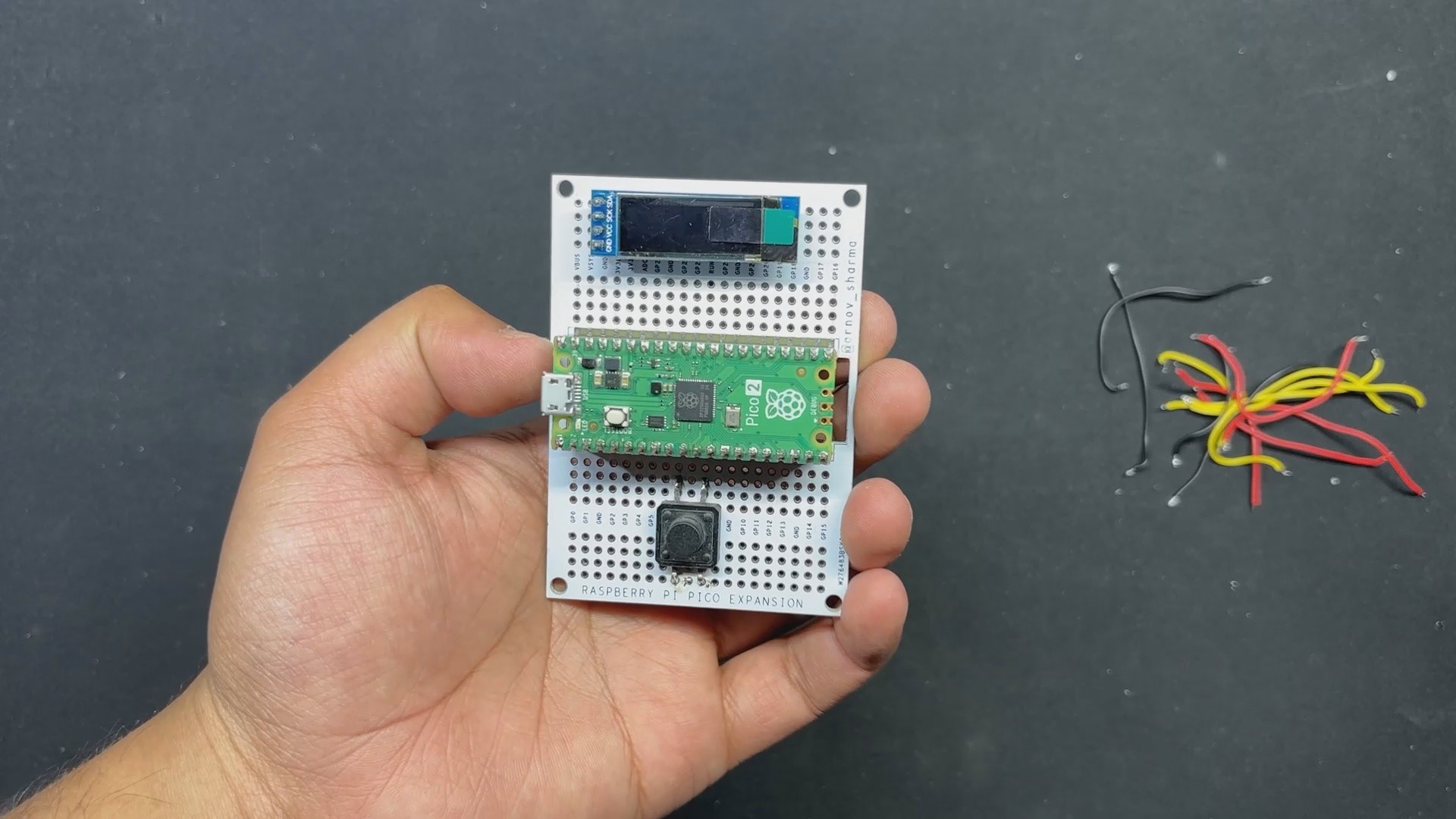
1Breadboard Version
![]()
![]()
![]()
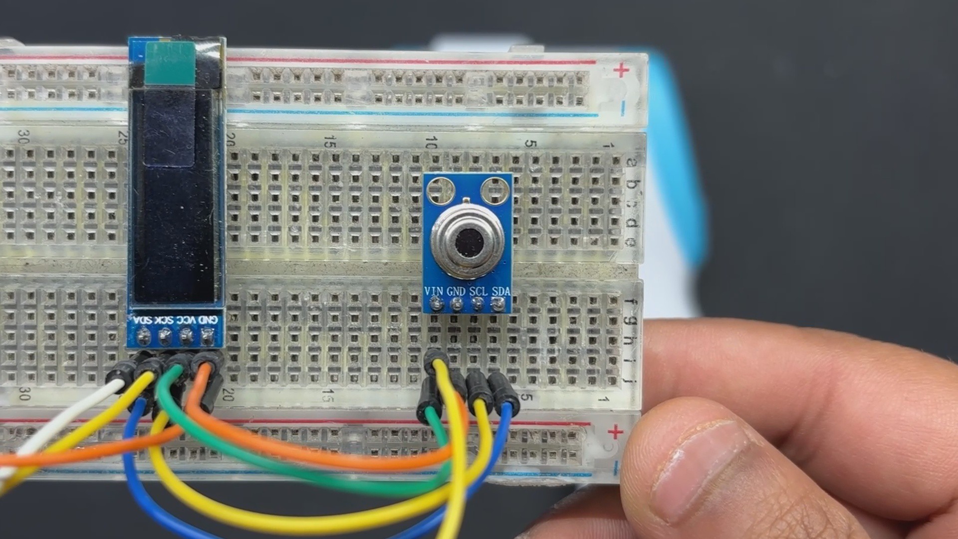
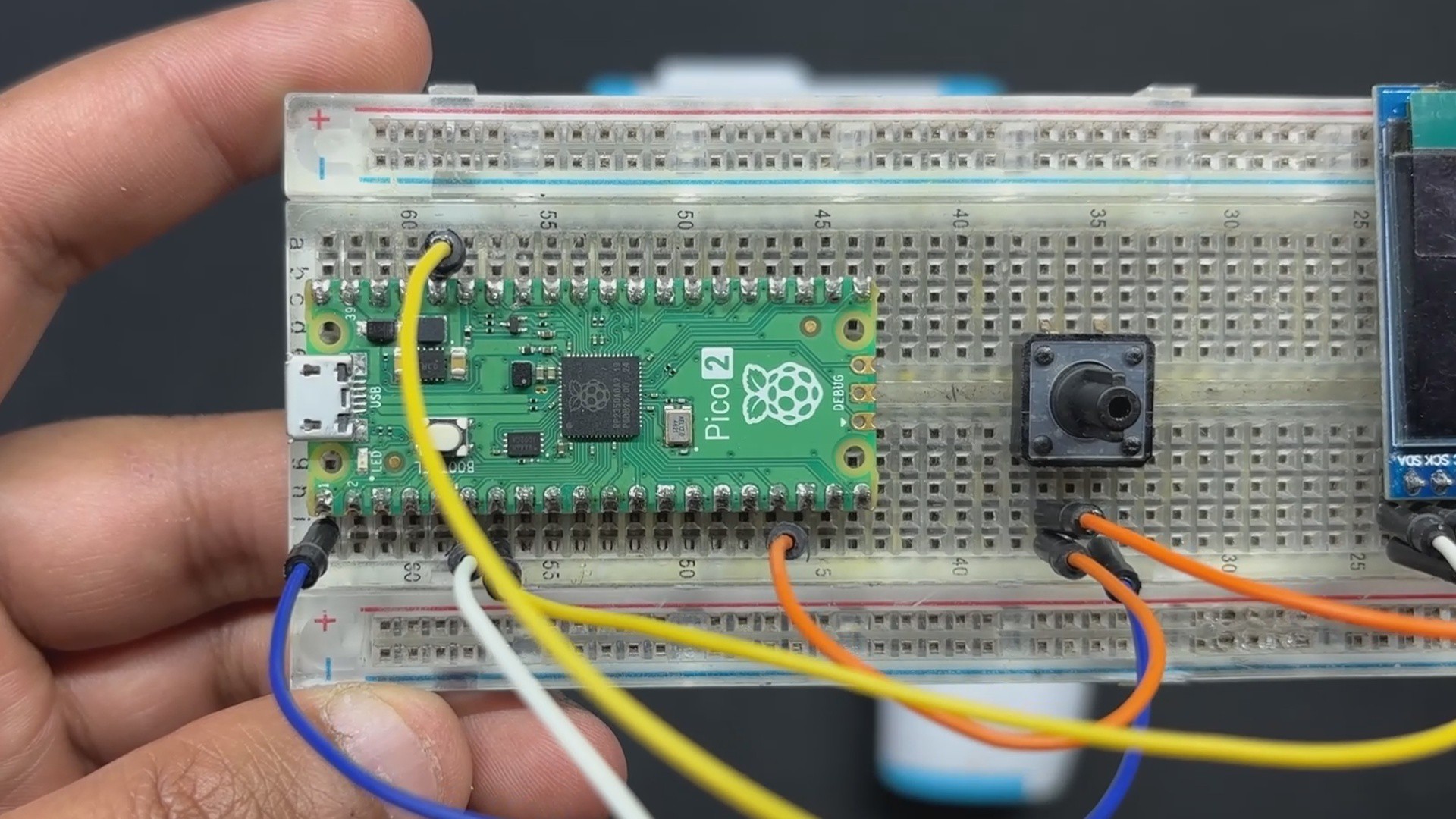
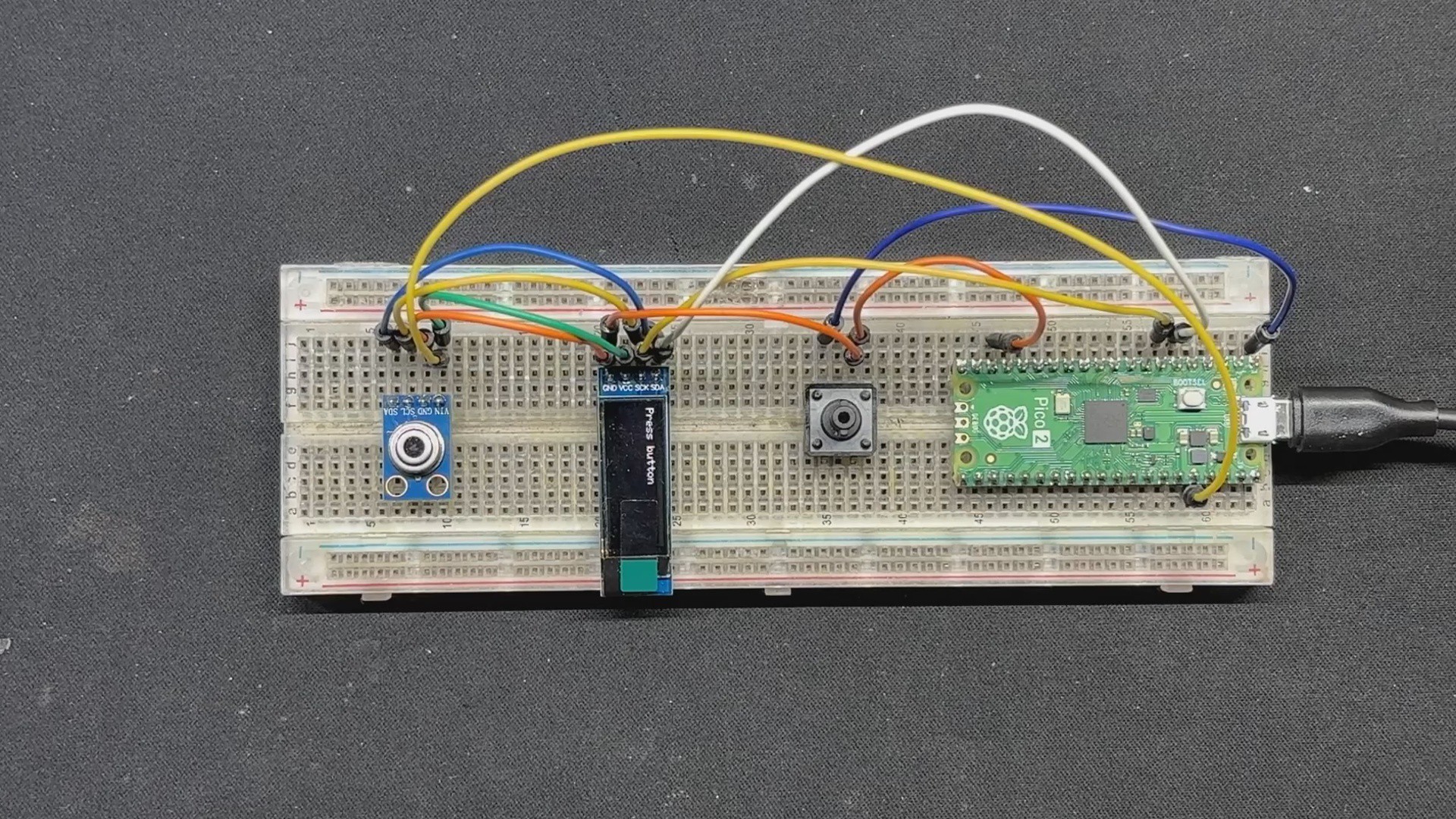
We begin the project by setting up the breadboard version. We start by placing all four components on the breadboard: the PICO 2, switch, OLED screen, and temperature sensor.
Next, we connect the GND of the PICO to the switch 1 input; the GND of the OLED screen is likewise linked to the GND of the PICO and the temperature sensor.
We next connect the VCC of the display and temperature sensor to the PICO's 5V supply.
The button's second terminal is connected to GPIO0 next.
Now, we connect PICO's I2C, GPIO4 (SDA) and GPIO5 (SCL), to the SDA and SCL pins of the display and temperature sensor in parallel.
After connecting the wires, we input the main code into the device, which only displays the current temperature measured by the temperature sensor when the button is pressed.
-
2CODE
Here's the code for this project and its a simple one.
#include <Wire.h>
#include <Adafruit_GFX.h>
#include <Adafruit_SSD1306.h>

#define SCREEN_WIDTH 128
#define SCREEN_HEIGHT 32
#define OLED_RESET    -1
Adafruit_SSD1306 display(SCREEN_WIDTH, SCREEN_HEIGHT, &Wire, OLED_RESET);

const int buttonPin = 0; // GPIO0 pin for button
const int sensorAddress = 0x5A; // GY-906-BAA I2C address

void setup() {
  Serial.begin(9600);
  pinMode(buttonPin, INPUT_PULLUP);
  Wire.begin();

  // SSD1306 OLED display initialization
  if (!display.begin(SSD1306_SWITCHCAPVCC, 0x3C)) {
    Serial.println(F("SSD1306 allocation failed"));
    for(;;);
  }
  display.display();
  delay(2000); // Pause for 2 seconds
  display.clearDisplay();
  display.setTextSize(1);
  display.setTextColor(SSD1306_WHITE);
  display.setCursor(0, 0);
  display.print("Press button");
  display.display();
}

void loop() {
  int buttonState = digitalRead(buttonPin);
  Serial.print("Button State: ");
  Serial.println(buttonState);

  if (buttonState == LOW) { // Button is pressed when LOW with INPUT_PULLUP
    Serial.println("Button Pressed");
    float temperature = readTemperature();
    Serial.print("Temperature: ");
    Serial.println(temperature);
    display.clearDisplay();
    display.setCursor(0, 0);
    display.print("Temp: ");
    display.print(temperature);
    display.print(" C");
    display.display();
  } else {
    display.clearDisplay();
    display.setCursor(0, 0);
    display.print("Press button");
    display.display();
  }
  delay(100);
}

float readTemperature() {
  Wire.beginTransmission(sensorAddress);
  Wire.write(0x07);
  Wire.endTransmission(false);
  Wire.requestFrom(sensorAddress, 3);

  int16_t tempData = Wire.read();
  tempData |= Wire.read() << 8;

  float temperature = tempData * 0.02 - 273.15;
  return temperature;
}
The project code starts by initiating contact with the GY-906 sensor and requesting temperature data. The sensor then returns a 16-bit raw temperature reading, which is converted to Celsius by applying the calculation tempData * 0.02 - 273.15.
When you hit the button, the code reads the temperature from the sensor and shows it on the OLED panel. In addition, the button state and temperature values are sent to the serial monitor for troubleshooting.
Before using this sketch, make sure you have installed the OLED screen libraries.
-
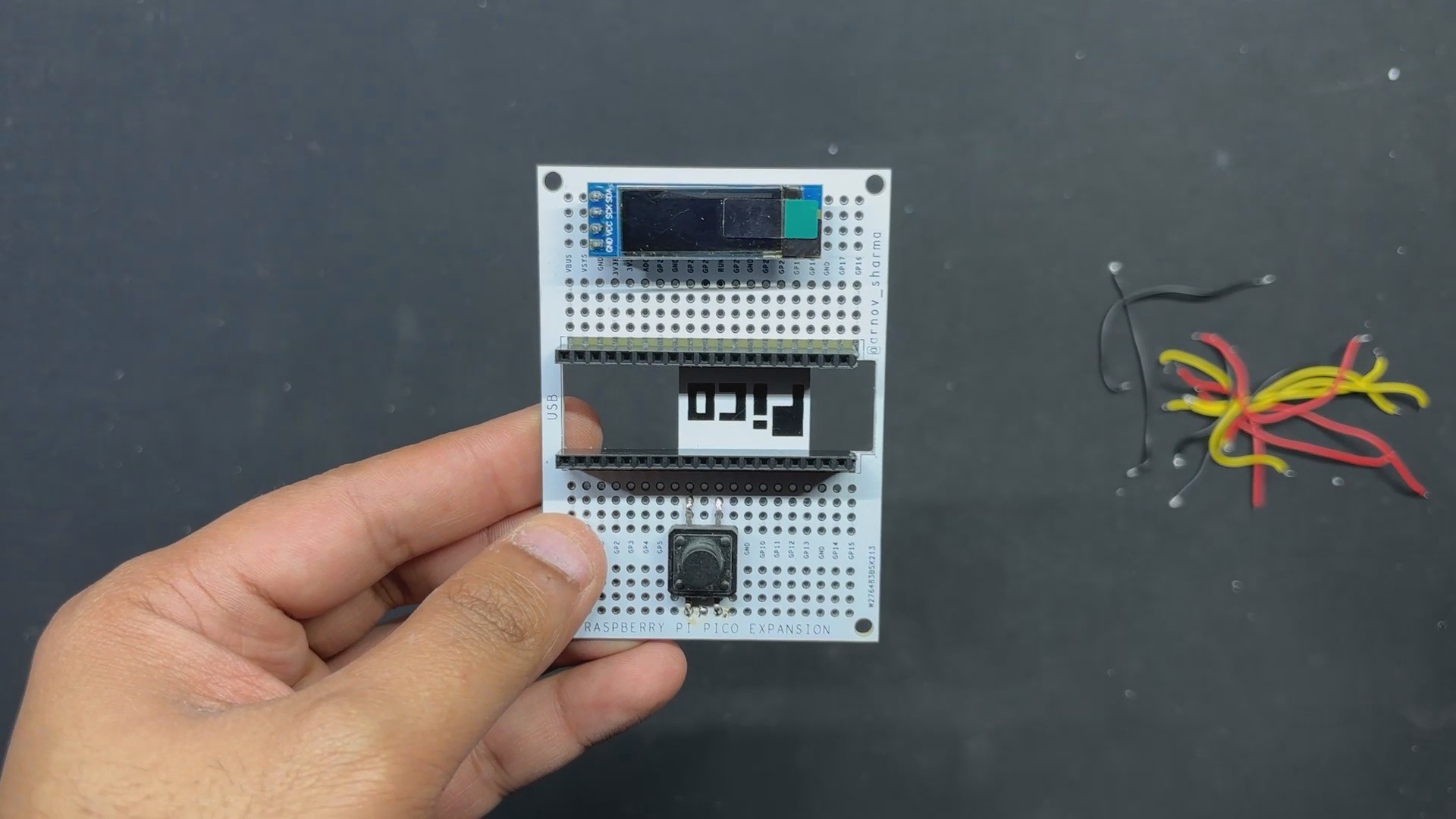
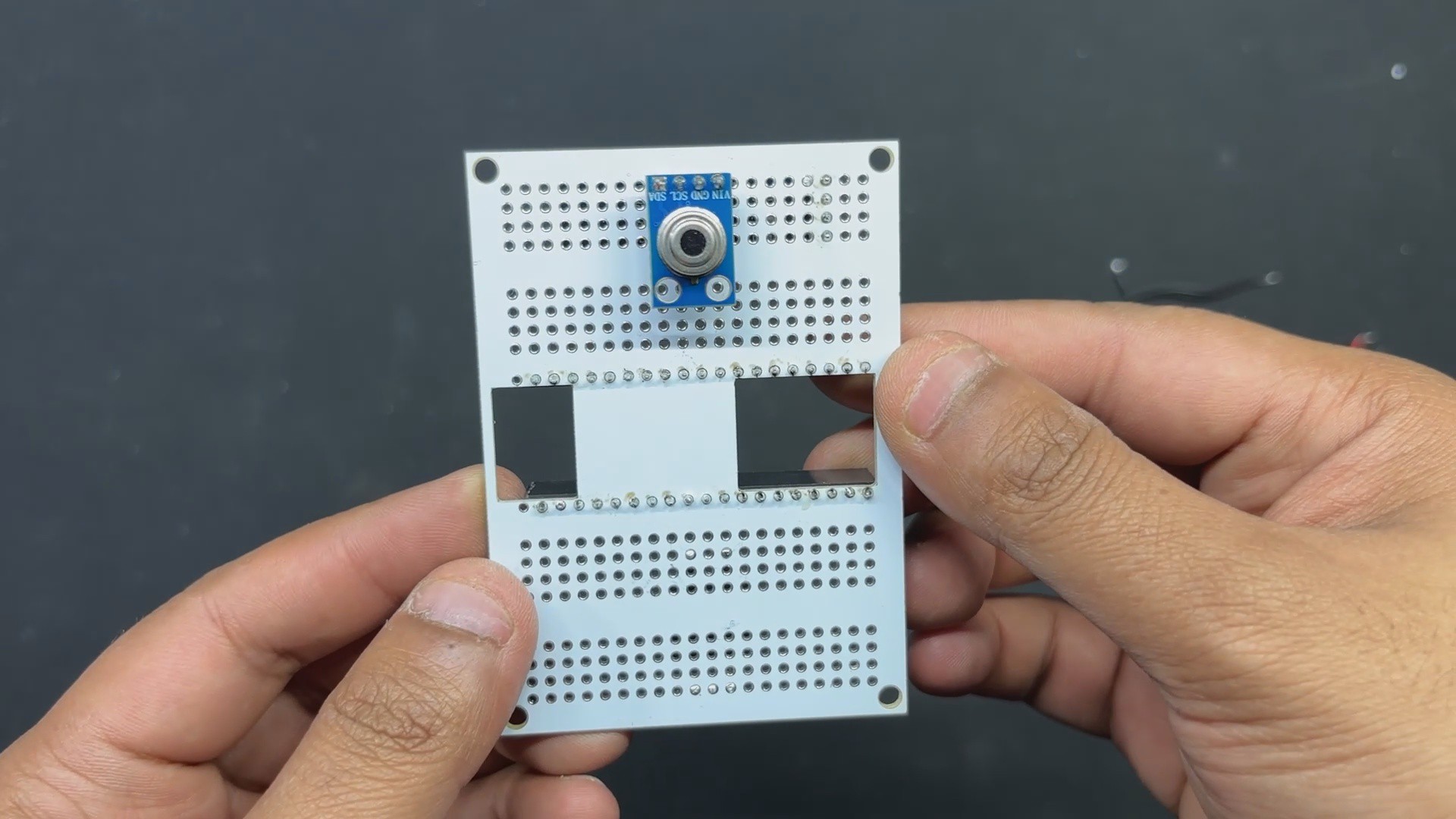
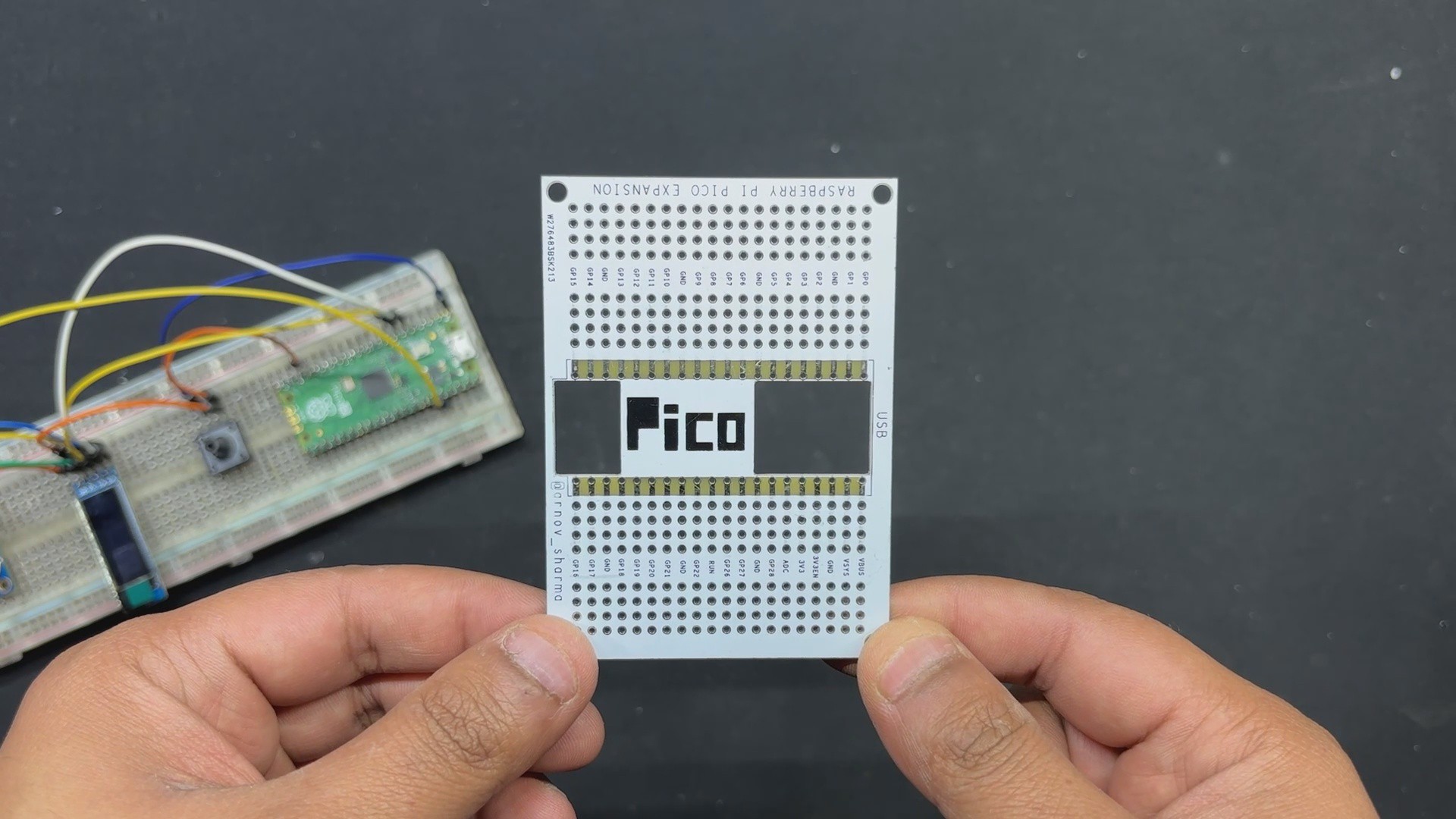
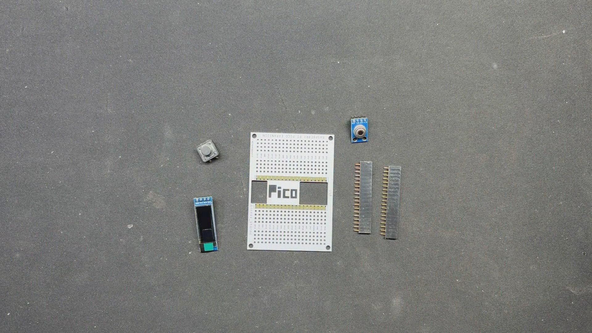
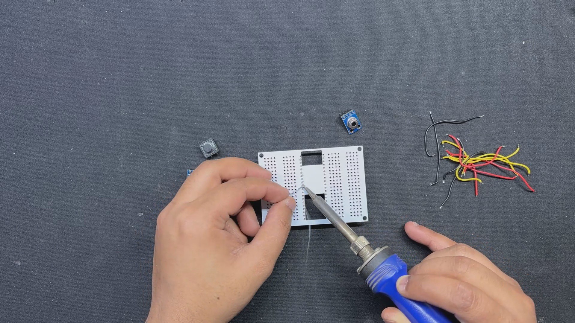
3Makeshift PCB Version
![]()
![]()
![]()
![]()
![]()
![]()
We are now preparing the Makeshift PCB Version, which involves mounting all of the components on our special prototype PCB and wiring them to create a working prototype.
- To install the PICO 2, we start by placing the female header pin on the PCB.
- The OLED screen and switch were then placed on the top side.
- We attached the temperature sensor to the PCB's back side.
- After installing all of the components, we begin to connect their pads together using connecting wires. We begin by connecting the GND of all components together.
- Next, we connect 5V of PICO to the VCC of the temperature sensor and the OLED panel.
- PICO's SDA (GPIO4) and SCL (GPIO5) are now connected to the temperature sensor and OELD screen's SDA and SCL pins, respectively.
- Finally, we added GPIO0 to the button terminal.
The wiring process is now complete, and our prototype circuit for the temperature gun is ready.
-
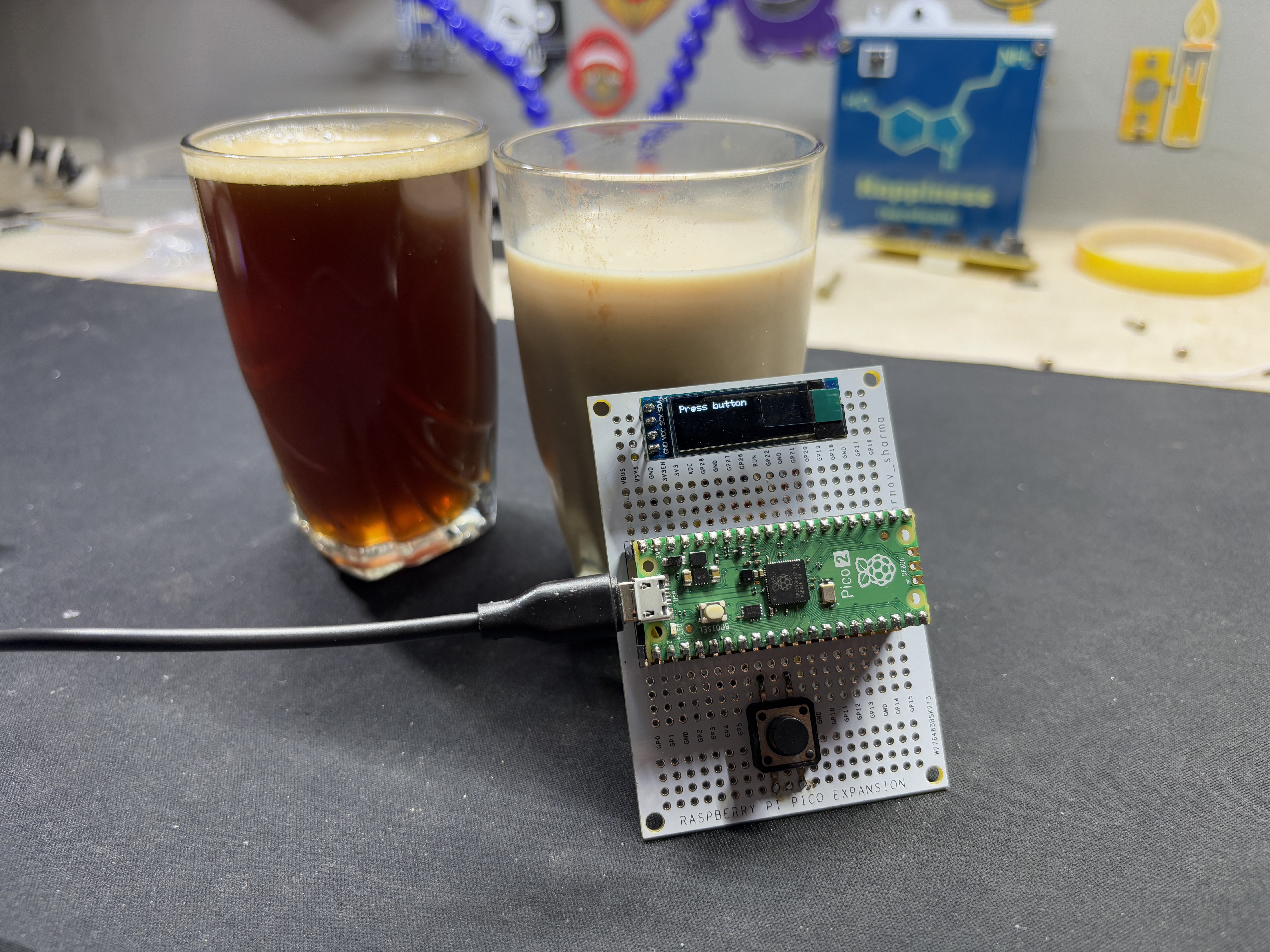
4Result/Conclusion
![]()
The end result of this basic but helpful project is a working temperature gun that shows the temperature of media using thermal radiation detected by the GY-906 sensor. A distance of roughly 1 cm is usually recommended for exact surface temperature measurements, but this varies based on the size and proportion of the media.
For the final test of this equipment, we made two distinct coffees: a hot black Americano and a cold coffee. First, we measured the hot coffee and obtained a temperature reading of 45°C. Next, we took readings from our cold medium, cold coffee, which gave us a temperature of 20 °C. cold coffee was not very cold, and hot coffee was lukewarm.
The Temperature Gun prototype is functioning, and we can now plan the second iteration of this project, which will employ the Thermal Gun 3D printed enclosure and include a custom PCB with a lithium cell to make the setup more convenient and portable to use.
This project was successful overall, and i Will be preparing Version 2 in the upcoming months so stay tuned for that.
Please let me know if you require any additional assistance; all the documents, files, and code are included in the article.
Thanks for reaching this far, and I will be back with a new project pretty soon.
Peace.
PICO TEMPERATURE GUN Version 1
Raspberry Pi PICO 2 Powered TEMP GUN based around the GY-906 Infrared Temp Module.
Discussions
Become a Hackaday.io Member
Create an account to leave a comment. Already have an account? Log In.