Doctor Volt
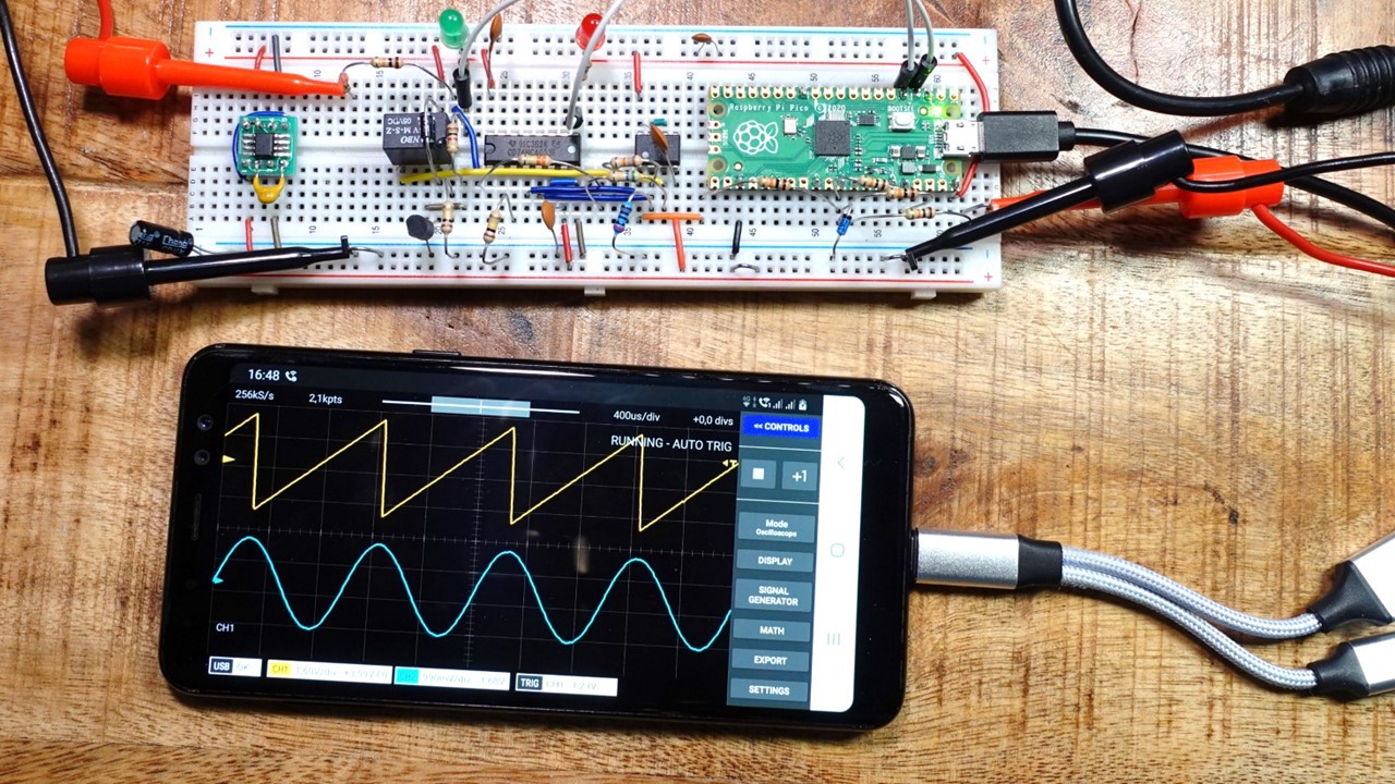
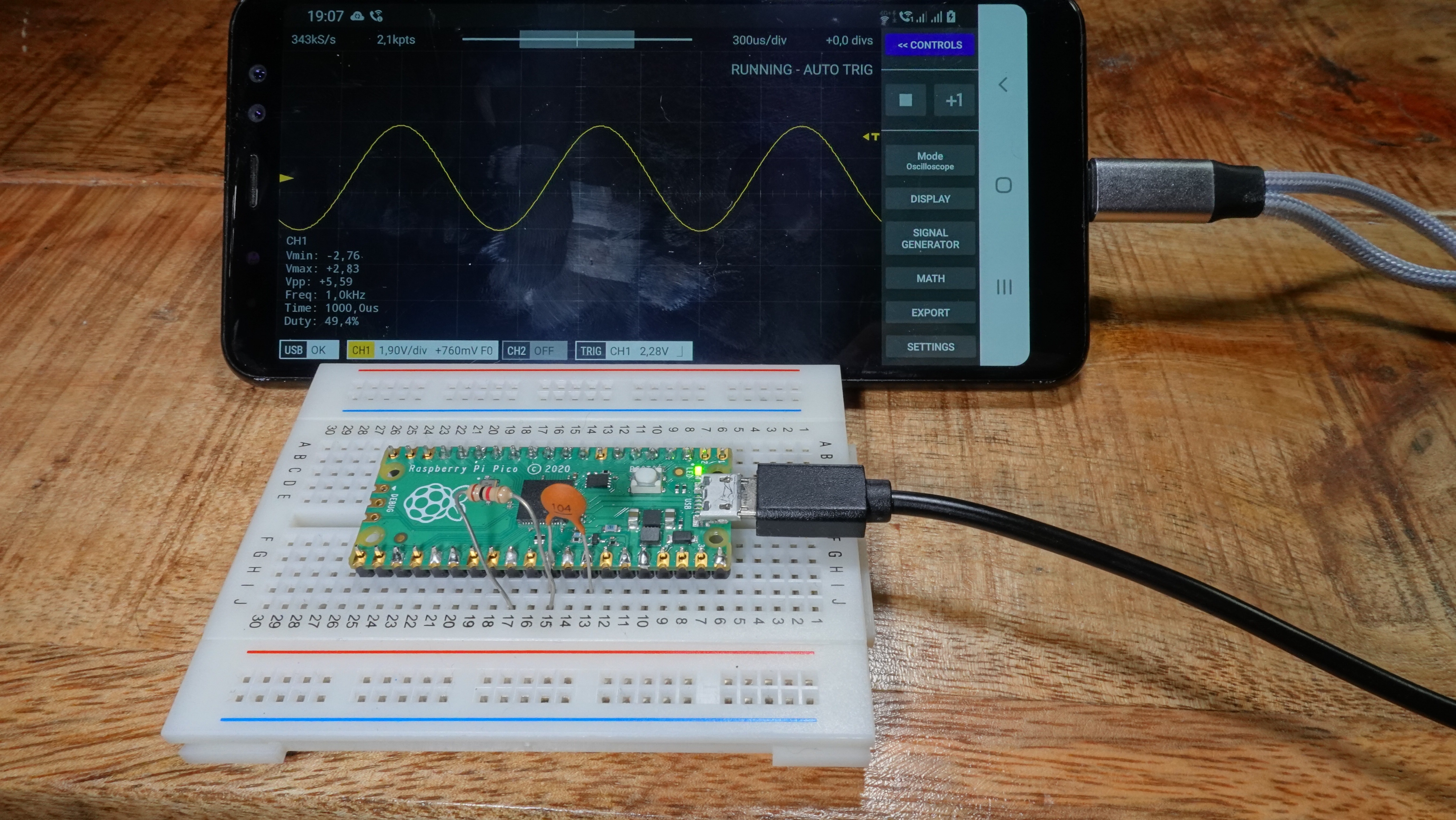
The ADCs of the RP2040 work with input voltages between 0 and 3.3 volts. Negative voltages and voltages above 3.3 volts cannot be measured and can even damage the chip. Therefore, an analog frontend is required—a circuit that amplifies or attenuates the measured voltages to the permissible range of 0 to 3.3 volts. Although the creators of Scoppy offer one on their website, it has not been available for some time. I was also unable to find a freely available circuit diagram, so I developed my own frontend. This offers three input voltage ranges, selectable via the app: -330 to 330 millivolts, -3.3 to 3.3 volts, and -33 to 33 volts. Probes can be connected via two BNC sockets. For calibration and testing, there is a simple signal generator capable of generating square wave signals up to 1.25 megahertz, as well as a pulse-width modulated 1-kHz sine signal. Also included is an 8-channel logic analyzer that operates at up to 25 million samples per second. When selecting the components, I made sure to use through-hole technology (THT) components as much as possible. For the few SMD components, there are adapter boards available online that allow them to be soldered onto. This makes it easy to assemble the frontend on a breadboard or a perfboard.