 yaluke
As I found in chapter 1, my TP-Link TL-WR1043ND ver 1.8 router has a JTAG port available on the board. This discovery opens up exciting possibilities for deeper exploration and manipulation of the device. JTAG (Joint Test Action Group) is a powerful interface that allows direct access to the router's hardware, enabling advanced debugging, firmware extraction, and even potential security research.
In this chapter, we'll delve into connecting to the JTAG port using a Raspberry Pi 5 as our debugging tool. This approach offers a cost-effective and accessible method for hardware enthusiasts and security researchers to interact with the router at a low level. We'll explore the capabilities of JTAG, from basic connectivity to more advanced operations like dumping the router's flash memory.
Let's embark on this journey to unlock the full potential of our TP-Link router through the power of JTAG interfacing.
What is JTAG?
JTAG, which stands for Joint Test Action Group, is a powerful and versatile hardware interface standard that has become integral to electronics testing, debugging, and programming. Originally developed in the 1980s, JTAG was designed to address the challenges of testing increasingly complex printed circuit boards (PCBs) with densely packed components.
At its core, JTAG provides a standardized method for accessing and controlling the pins of integrated circuits (ICs) on a PCB without the need for physical probing. This is achieved through a simple serial interface, typically consisting of four or five pins:
- TCK (Test Clock)
- TMS (Test Mode Select)
- TDI (Test Data In)
- TDO (Test Data Out)
- TRST (Test Reset, optional)
JTAG's primary functions include:
- Boundary Scan Testing: Allows for testing interconnections between ICs on a PCB without direct physical access.
- Debugging: Provides access to internal chip resources, enabling developers to inspect and modify registers, memory, and system state.
- Programming: Facilitates in-system programming of devices like FPGAs and flash memory.
The JTAG interface has become so ubiquitous that it's now found in most modern microprocessors, FPGAs, and many other types of ICs. Its versatility has made it an essential tool for hardware developers, allowing them to test, debug, and program devices throughout the development lifecycle and even after product deployment.
Raspberry Pi 5 as a JTAG debugging tool
The Raspberry Pi 5, released in late 2023, introduces a powerful yet cost-effective platform for JTAG debugging, particularly suited for enthusiasts and researchers working on projects like our TP-Link TL-WR1043ND router exploration. Priced at around $80 USD, it offers an accessible entry point into advanced hardware debugging.
Key features of the Raspberry Pi 5 as a JTAG debugging tool include:
- Improved processing power with the BCM2712 chip
- Enhanced GPIO capabilities
- Compatibility with standard JTAG protocols
However, the platform does come with some limitations:
- Limited official documentation for the new RPi I/O chipset (RP1)
- Lack of RTCK (Return Test Clock) support, affecting adaptive JTAG clocking
Despite these challenges, the Raspberry Pi 5 excels in firmware extraction tasks, achieving speeds of approximately 850 KB/s. However, it may show some limitations in real-time register access compared to dedicated professional debuggers.
The platform's versatility and low cost make it an attractive option for hobbyists and researchers, especially those working on projects like our router exploration. While it requires some additional configuration and workarounds, the Raspberry Pi 5 offers a powerful and flexible solution for JTAG debugging tasks.
Physical Connection: Raspberry Pi 5 to TP-Link JTAG Interface
JTAG Connector Identification
The TP-Link TL-WR1043ND v1.8 features a 14-pin EJTAG 2.6 standard header located near the serial port (labeled “JP1" on PCB):
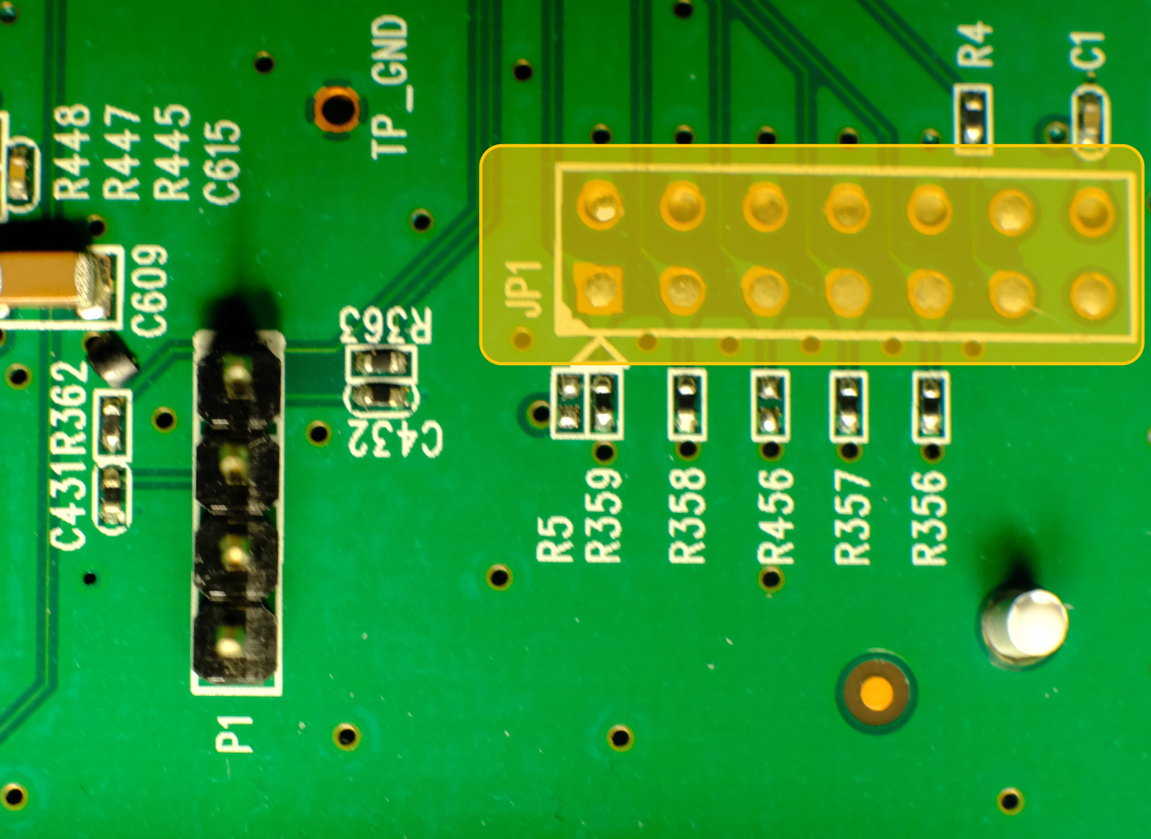
This aligns with OpenWRT documentation confirming MIPS EJTAG compliance. The JTAG 2.6 header follows this pin arrangement:
| Pin | Signal | Function |
| 1 | nTRST | Test Reset (Optional) |
| 3 | TDI | Test Data In |
| 5 | TDO | Test Data Out |
| 7 | TMS | Test Mode Select |
| 9 | TCK | Test Clock |
| 11 | nSRST | System Reset (optional) |
| 2, 4, 6, 8, 10 | GND | Ground |
| 14 | VREF | Voltage Reference (3.3V) |
| 12, 13 | Not used |
Minimal Raspberry Pi 5 Connection Scheme
| Router JTAG Pin | RPi 5 GPIO | Physical Pin | Signal Voltage |
| 3 (TDI) | GPIO26 | Pin 37 | 3.3V |
| 5 (TDO) | GPIO24 | Pin 18 | 3.3V |
| 7 (TMS) | GPIO27 | Pin 13 | 3.3V |
| 9 (TCK) | GPIO25 | Pin 22 | 3.3V |
| 2 (GND) | GND | Pin 39 | - |
Connection notes:
- Voltage compatibility: both devices use 3.3V logic - no level shifter required.
- It’s worth to solder goldpin header for stable connection.
- Maximum cable length: 15cm.
- ESD protection: work on grounded surface, use anti-static wrist strap.
- Connection sequence: router power off -> connect GND first -> connect signals -> power on router.
- Floating pins: unused JTAG pins should be left disconnected.
- Common pitfall: swapping TDO/TDI pins.
Raspberry Pi 5 software configuration
With physical connections established, we configure Raspberry Pi OS (Bookworm) for JTAG operation. On a fresh, updated system:
Enable JTAG in boot configuration:
sudo nano /boot/firmware/config.txt
Add following lines under [all] section:
enable_jtag_gpio=1
gpio=22-27=a4
And reboot RPi.
To connect to the router OpenOCD (Open On-Chip Debugger) will be used. OpenOCD is a tool for debugging, in-system programming, and boundary-scan testing for embedded devices. Install dependencies first, then clone and build the tool
sudo apt install git libtool pkg-config autoconf automake texinfo libusb-1.0-0-dev libgpiod-dev build-essential
git clone https://github.com/raspberrypi/openocd.git
cd openocd
./bootstrap
./configure --enable-linuxgpiod
make -j$(nproc)
sudo make install
After successful installing OpenOCD create configuration file for this tool - name it rpi5-jtag.cfg and add following content:
adapter driver linuxgpiod

adapter gpio tck 25 -chip 4
adapter gpio tms 27 -chip 4
adapter gpio tdi 26 -chip 4
adapter gpio tdo 24 -chip 4
adapter gpio trst 22 -chip 4

transport select jtag

source [find target/atheros_ar9331.cfg]
Last, optional line add hardware specific configuration to this file - as there is no config for Atheros AR9132, similar (working) chipset is used. To verify if it works type:
sudo openocd -f rpi5-jtag.cfg
And check if there are no warnings or errors in the output:
Open On-Chip Debugger 0.12.0+dev-gcf9c0b41c (2025-03-24-21:05)
Licensed under GNU GPL v2
For bug reports, read
    http://openocd.org/doc/doxygen/bugs.html
ar9331_ddr2_init
Info : Listening on port 6666 for tcl connections
Info : Listening on port 4444 for telnet connections
Info : Linux GPIOD JTAG/SWD bitbang driver
Info : Note: The adapter "linuxgpiod" doesn't support configurable speed
Info : JTAG tap: ar9331.cpu tap/device found: 0x00000001 (mfg: 0x000 (<invalid>), part: 0x0000, ver: 0x0)
Info : [ar9331.cpu] Examination succeed
Info : starting gdb server for ar9331.cpu on 3333
Info : Listening on port 3333 for gdb connections
Now OpenOCD runs and waits for connection.
Dumping flash using JTAG
As OpenOCD reported, it listening on port 4444 for telnet connection. Let’s switch to another terminal; after installing telnet and connecting to our device using following commands:
sudo apt install telnet

telnet localhost 4444
We should see:
Trying ::1...
Connection failed: Connection refused
Trying 127.0.0.1...
Connected to localhost.
Escape character is '^]'.
Open On-Chip Debugger
>
We are in! Now we can play with the router - check available commands with help (there are a lot more possibilities than using UART). To dump flash content (without custom script with error handling as we did in the chapter 1) type:
> halt
> dump_image full_flash.bin 0xbf000000 0x800000
And after around 40 minutes binary file is on the disk.
This configuration leverages the RP1's GPIO interface despite its performance limitations, providing a functional open-source alternative to commercial JTAG debuggers. The GPIO mapping reflects physical constraints of the Pi 5's revised layout compared to earlier models.
Discussions
Become a Hackaday.io Member
Create an account to leave a comment. Already have an account? Log In.