 Stepan Skopivskiy
After solving the ignition problem, the hardware buttons did not start to work. However, the bit responsible for the KL15 changed its value from 0 to 1. According to the LDF, in addition to the KL15 and Buttons, the frame also contains the ZV_auf_Funk, ESP_v_Signal_8Bit, and UGDO_Switchboard.
UGDOe_02: 46, BCM1, 6 {
    UGDO_Buttons, 0 ;
    Klemme_15, 6 ;
    ZV_auf_Funk, 7 ;
    ESP_v_Signal_8Bit, 8 ;
    UGDO_Switchboard, 16 ;
    SM_Parken_UGDO_Anf, 24 ;
    SM_Parken_UGDO_Aktion, 28 ;
  }

UGDOs_02: 47, UGDO_S, 8 {
    UGDO_LED_Code_01, 0 ;
    UGDO_Function_01, 5 ;
    UGDO_Failure_Antenne, 8 ;
    UGDO_Failure_Codierung, 9 ;
    UGDO_Failure_Hardware, 10 ;
    UGDO_ResponseError, 16 ;
    UGDO_Channel_1, 24 ;
    UGDO_Channel_2, 25 ;
    UGDO_Channel_3, 26 ;
    UGDO_Channel_4, 27 ;
    UGDO_Channel_5, 28 ;
    UGDO_Channel_6, 29 ;
    UGDO_Channel_7, 30 ;
    UGDO_Channel_8, 31 ;
    UGDO_Channel_9, 32 ;
    UGDO_Channel_10, 33 ;
    UGDO_Channel_11, 34 ;
    UGDO_Channel_12, 35 ;
    UGDO_Channel_13, 36 ;
    UGDO_Channel_14, 37 ;
    UGDO_Channel_15, 38 ;
    UGDO_DoorState, 40 ;
  }
The example pair of the LIN bus request/response frames is the next two messages:
0x2E70FFFC80FFFFE3
0x2F00F9FE0080F0FFFF26
From the previous experience, the first byte (0x2A and 0x2F) is the LIN frame ID. The last byte is the checksum (0x84 and 0x26). After converting 0x2E to decimals, it is 46, and 0x2F = 47. So, the clear data is:
0x70FFFC80FFFF
0x00F9FE0080F0FFFF
When converting the HEX to bits, the bits will be inverted because of the LIN specification. In the LIN bus, the 0-bit goes first.
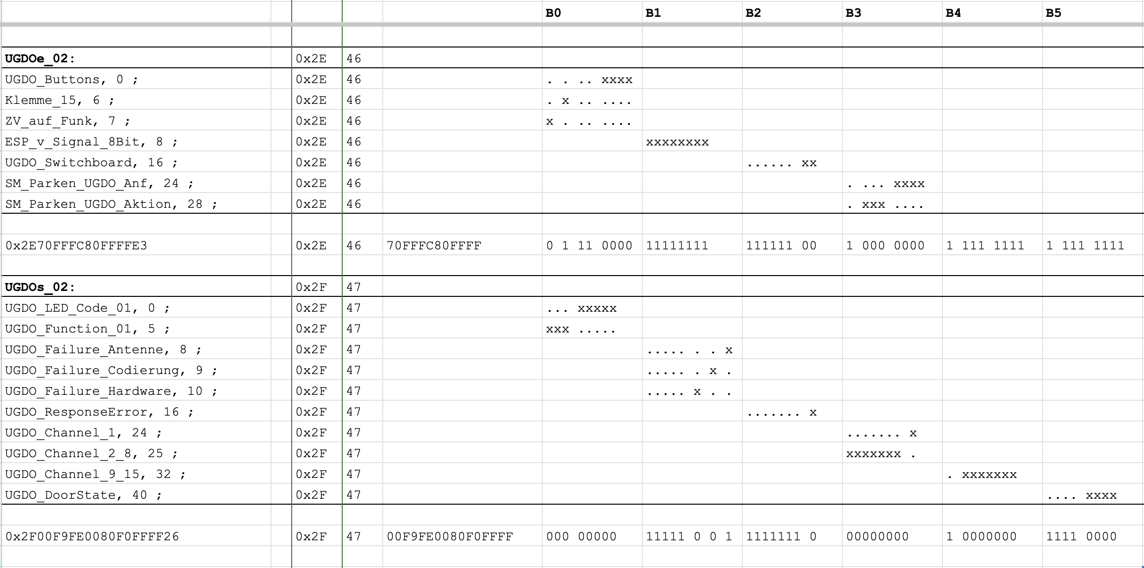
So, here we go. The "decoded" from the LIN frame data is now readable for us. The first byte is responsible for UGDO_Buttons, Klemme_15, and ZV_auf_Funk. It means that the state of the buttons is sent to the HomeLink as is, and they are zero. The next bit is responsible for the KL15 state. So, now it describes why putting the power to the BCM KL15 input is not enough. It looks like all digital communication about the KL15 is isolated from the hardware. The last one bit is the ZV_auf_Funk, but unfortunately, it had no description in the LDF.
The next byte is ESP_v_Signal_8Bit, and it is pretty self-explanatory. But why is it 0xFF? Maybe it is a problem why the buttons not reacts. Because the HomeLink module thinks that the car is speeding. And the LDF has information about that.
ESP_v_Signal_8Bit_encoding {
  physical_value, 0, 253, 2.56, 0, "Unit_KiloMeterPerHour" ;
  logical_value, 254, "Init" ;
  logical_value, 255, "Error" ;
}
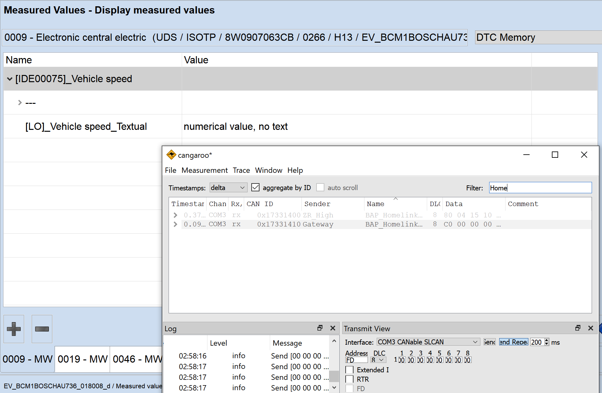
Now, it was necessary to tell BCM the Zero speed somehow. To do that, we can check the dbc file (CAN Matrix or CAN Database). Based on the name, it receives the speed from the ESP, but the ESP and BCM have different communication buses. VAG is using the module called "Gateway" to commutate that buses, so the information with the speed should come from it with high chance. And it is:
BO_ 253 ESP_21: 8 Gateway
 SG_ ESP_21_CRC : 0|8@1+ (1,0) [0|255] ""  Vector__XXX
 SG_ ESP_21_BZ : 8|4@1+ (1,0) [0|15] ""  Vector__XXX
 SG_ BR_Eingriffsmoment : 12|10@1+ (1,-509) [-509|509] ""  Vector__XXX
 SG_ ESP_Diagnose : 23|1@1+ (1.0,0.0) [0.0|1] ""  ZR_High
 SG_ ESC_v_Signal_Qualifier_High_Low : 24|3@1+ (1.0,0.0) [0.0|7] ""  Vector__XXX
 SG_ ESP_Vorsteuerung : 28|1@1+ (1.0,0.0) [0.0|1] ""  Vector__XXX
 SG_ OBD_Schlechtweg : 30|1@1+ (1.0,0.0) [0.0|1] ""  ZR_High
 SG_ OBD_QBit_Schlechtweg : 31|1@1+ (1.0,0.0) [0.0|1] ""  ZR_High
 SG_ ESP_v_Signal : 32|16@1+ (0.01,0) [0.00|655.32] "Unit_KiloMeterPerHour"  BedienSG_hi,DDA,OTA_FC,ZR_High,ZR_LIMU,ZR_MIB_TOP_ab_Gen3,ZR_Standard
 SG_ ASR_Tastung_passiv : 48|1@1+ (1.0,0.0) [0.0|1] ""  OTA_FC
 SG_ ESP_Tastung_passiv : 49|1@1+ (1.0,0.0) [0.0|1] ""  OTA_FC,ZR_High,ZR_LIMU,ZR_MIB_TOP_ab_Gen3
 SG_ ESP_Systemstatus : 50|1@1+ (1.0,0.0) [0.0|1] ""  OTA_FC
 SG_ ASR_Schalteingriff : 51|2@1+ (1.0,0.0) [0.0|3] ""  Vector__XXX
 SG_ ESP_QBit_v_Signal : 55|1@1+ (1.0,0.0) [0.0|1] ""  ZR_High,ZR_LIMU,ZR_MIB_TOP_ab_Gen3,ZR_Standard
 SG_ ABS_Bremsung : 56|1@1+ (1.0,0.0) [0.0|1] ""  OTA_FC,ZR_High,ZR_LIMU,ZR_MIB_TOP_ab_Gen3
 SG_ ASR_Anf : 57|1@1+ (1.0,0.0) [0.0|1] ""  ZR_High
 SG_ MSR_Anf : 58|1@1+ (1.0,0.0) [0.0|1] ""  OTA_FC,ZR_High
 SG_ EBV_Eingriff : 59|1@1+ (1.0,0.0) [0.0|1] ""  Vector__XXX
 SG_ EDS_Eingriff : 60|1@1+ (1.0,0.0) [0.0|1] ""  Vector__XXX
 SG_ ESP_Eingriff : 61|1@1+ (1.0,0.0) [0.0|1] ""  OTA_FC,ZR_High
 SG_ ESP_ASP : 62|1@1+ (1.0,0.0) [0.0|1] ""  ZR_High
 SG_ ESC_Neutralschaltung : 63|1@1+ (1.0,0.0) [0.0|1] ""  Vector__XXX
The actual information based on DBC is the following:
- 16 bits, starting from 32th
- 0.01 Factor (Precision)
- 0 offset (e.g., 0 value = 0 speed) with a max value of 655,32 (0xFFFC)
ESP_v_Signal : 32|16@1+ (0.01,0) [0.00|655.32] "Unit_KiloMeterPerHour"
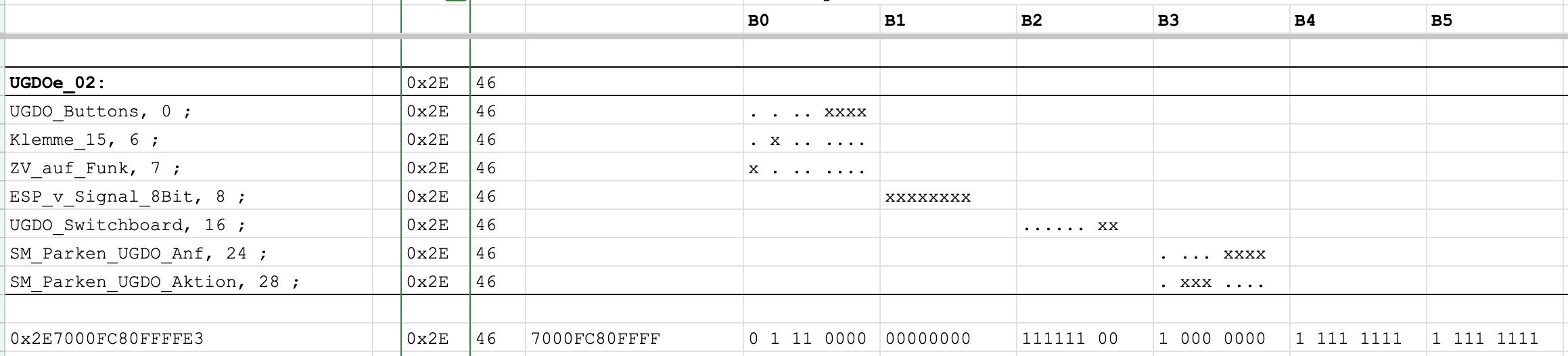
The car manual says that you can program the buttons only when the car is stationary. So, why not just send the message with this data to the CAN bus? We say, we do! To be sure, the message was zero, e.g., the data was 0x0000000000000000 (8 bytes of can message body). After that, BCM starts to report the speed as zero instead of a negative.
The LIN frames were changed, too. Now the ESP_v_Signal_8Bit is 0x00.
But the buttons were not reacting yet anyway!
The last "visible" item was the CP (Componen Protection). The BCM has an active error about it. But this problem is hard to resolve because it requires ODIS online. But as you remember from the previous log, I also had a melted BCM without the CP error. So, let's try to do the same with it, too. I connected BCM, BCM2, HomeLink buttons, module, and diagnosis interface, and CAN sniffer and start sending zero speed. The melted BCM had a lot of internal errors, but it was working.
And how surprised I was when the buttons started to respond! Finally! I was able to do clear and program. And even send the "command" to my RF relay.
Also, the other combination was tested with no lack. The healthy block with component protection does not send button states to the HomeLink module. Instead, when the reported speed is 0xFF and no CP, the HomeLink module does not drive the LEDs in buttons. So, now the final list of requirements is the following:
- Ignition ON, by wire and by CAN.
- No errors in BCM regarding UGDO (HomeLink module).
- Zero speed (Reported from CAN).
- No Component Protection.
Discussions
Become a Hackaday.io Member
Create an account to leave a comment. Already have an account? Log In.