 Stepan Skopivskiy
Besides successfully discovering the communication between the hardware buttons, another problem remained — there was absolutely nothing about the UGDO (universal garage door opener) BAP (German: “Bedien- und Anzeigeprotokoll” ~ control- and display protocol).
The only valuable paper I found was this one (from a web archive): https://web.archive.org/web/20241005094756/https://blog.dietmann.org/?p=324. I saved a copy in PDF format just in case. But even it did not have any mentions about the UGDO. Another interesting document I found was https://www.scribd.com/document/476121999/BAP-FC-NAV-SD-P30DF48-v2-80-F-pdf. It has also been saved as a pdf just for easy access. It describes how the other component (Navigation) communicates using BAP. Unfortunately, also it has a lot of references to other internal documents.
Another way was to start from the MMI. But here is just a bit of information too. The only mention of software of the MMI I found was this repository - https://github.com/grajen3/mib2-lsd-patching. It has a lot of mentions about the UGDO but as the code is just a decompiled Java classes there are a lot of missed constants too. The one of files is - https://github.com/grajen3/mib2-lsd-patching/blob/aa-in-vc/lsd_java/org/dsi/ifc/carcomfort/UGDOButtonListRA0.java. And the other files are on the screenshot.
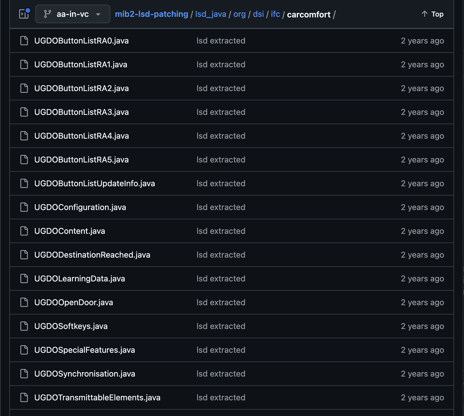
But as there are no constant values it was not so valuable, at least for now. The last way left was sniffing. The MMI uses the CAN to communicate with the BCM (through the gateway), and then the BCM communicates to UGDO by LIN. So, instead of sniffing the LIN the CAN was chosen. Also, the DBC (CAN messages matrix) file helps to filter the necessary messages. Sniffing can be done with the cheap module - https://canable.io/.
The first session was pretty useless. I start recording the CAN messages and start doing some actions like program, rename, delete buttons, etc. The result - just a mess of data and actions. Before the second session, an "action" plan was prepared.
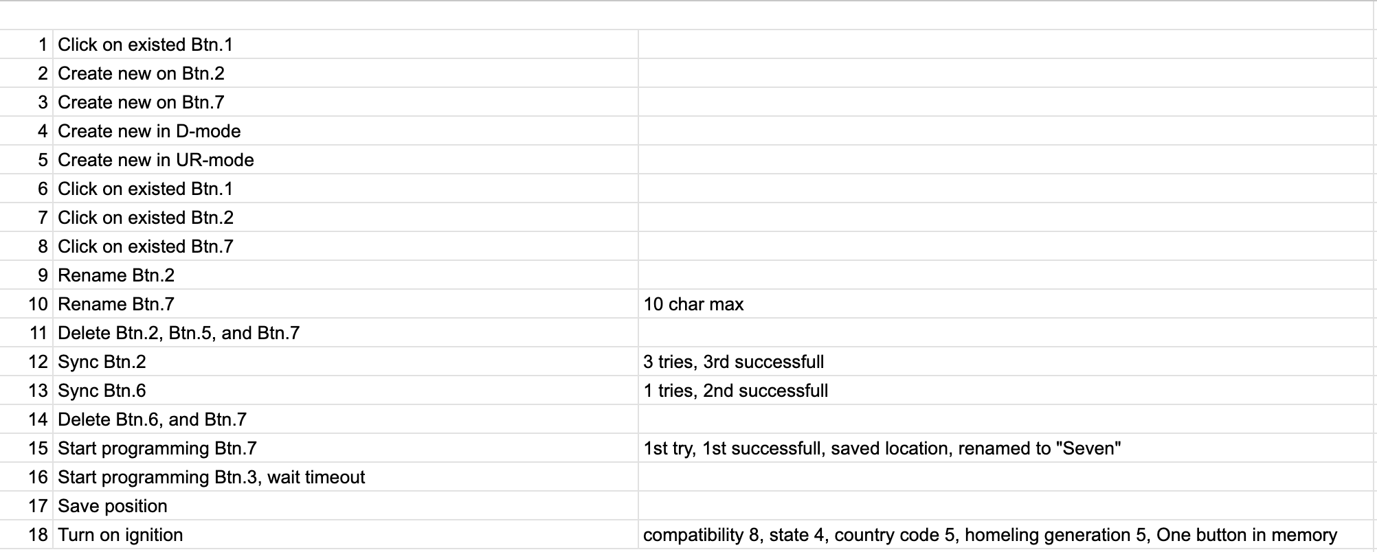
And now it is a valuable dataset. Using the BAP CAN message description mentioned at the log start, some data preparation was done. The screenshot shows the part of messages after the ignition turns on.
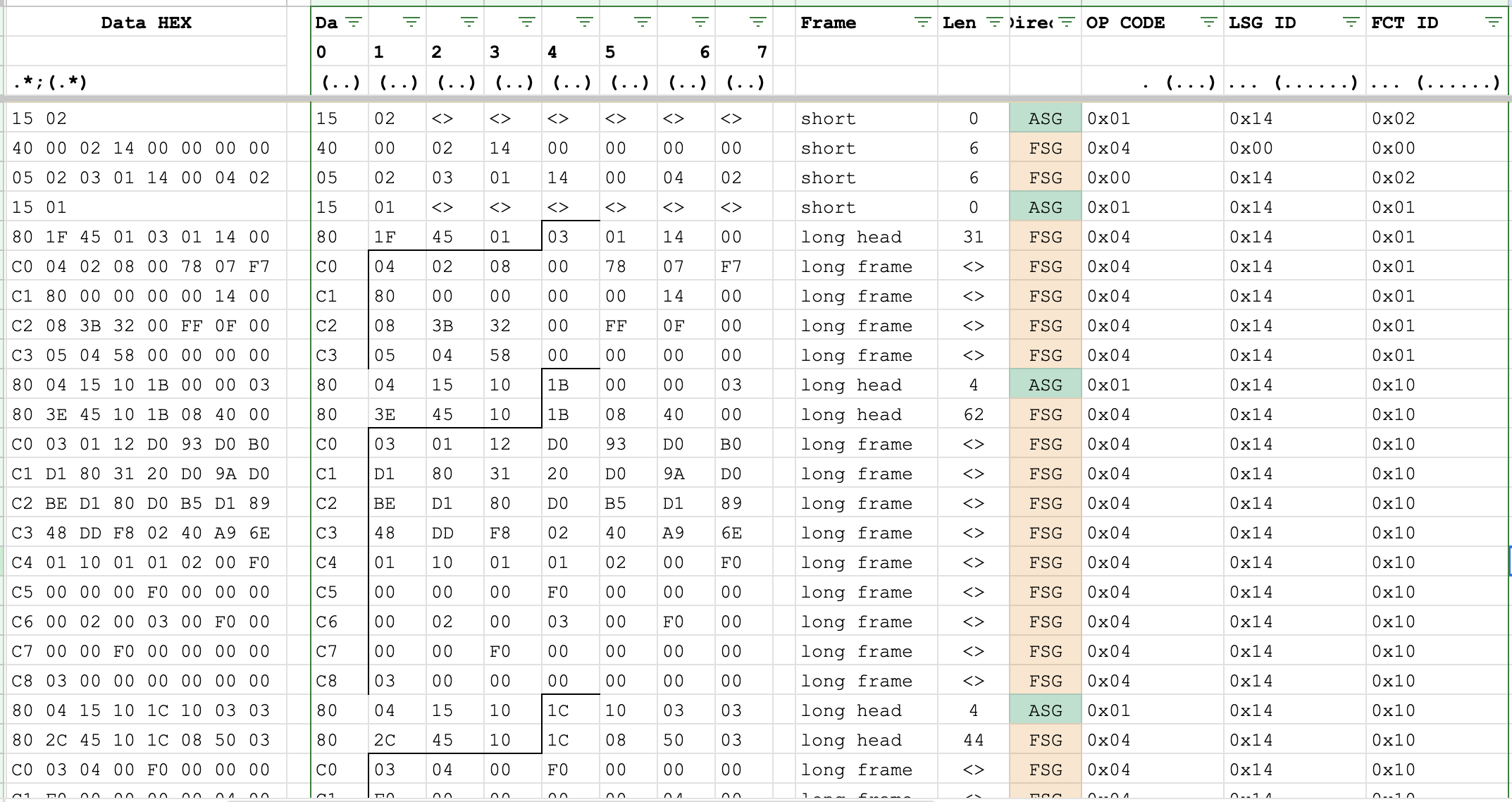
It shows the initialization of the BAP, FCT_ID: 0x02 and 0x01. The information about those function IDs was found in both sources: the BAP description blog and the NAV_SD_Bap document. And it looks like the common structure for any BAP member. Then, the specific function id goes - 0x10, with a long amount of data and some interesting repeating in it. Using the same doc, the collapsed data is the next:
0x1B084000030112D093D0B0D1803120D09AD0BED180D0B5D18948DDF80240A96E011001010200F0000000F00000000002000300F0000000F0000000000300
So long data can be only in an array. Thankfully in the NAV_SD doc file, there is general information about the array formats, they are the same between the different functions.
Based on found in Google information, BAP has four kinds of functions: property, method, array, and cache. Each of them has its own sets of op_codes.
Opcode value | Function class Property | Function class Array | Function class Method | Function class Cache | Direction |
0x0 | Set | SetArray | Start | – | ASG -> FSG |
Reset | FSG -> ASG | ||||
0x1 | Get | GetArray | Abort | GetAll | ASG -> FSG |
0x2 | SetGet | SetGetArray | StartResult | – | ASG -> FSG |
0x3 | HeartbeatStatus | ChangeArray | Processing | – | FSG -> ASG |
0x4 | Status | StatusArray | Result | StatusAll | FSG -> ASG |
0x5 | StatusAck | – | – | – | FSG -> ASG |
0x6 | Ack | – | – | – | ASG -> FSG |
0x7 | Error | Error | Error | Error | FSG -> ASG |
Based on the information, the sequence is the next: after turning on the ignition, the MMI requests the information and waits for the array from the module. Skipping the BAP message header etc, the clear request-response data is the next:
0x1B000003
0x1B084000030112D093D0B0D1803120D09AD0BED180D0B5D18948DDF80240A96E011001010200F0000000F00000000002000300F0000000F0000000000300
The get array op_code has the next format: ASG_ID, TAID, ArrayHeader. The ASG_ID (Identifies the requesting) and TAID (Identifies the transaction (pair of GetArray and StatusArray). The transaction ID (TAID) is unique in combination with the parameter ASG_ID) are the components of one byte.
The ArrayHeader also is the combination of parameters: Mode (4bit), RecordAddress (4bit), Start Number (1 byte), and Elements (1 byte).
And now, the request can be explained: 0x1B000003.
- 0x1 - ASG_ID
- 0xB - TAID
- 0x0 - Mode
- 0x0 - RecordAddress
- 0x00 Start Number
- 0x00 Elements
The same for the response. The common response is the combination of the next data: ASG_ID, TAID, TotalNumListElements, ArrayHeader, and Data. So, the parsed response is the next:
- 0x1 - ASG_ID
- 0xB - TAID
- 0x08 - TotalNumListElements (in array)
- 0x4 - Mode
- 0x0 - RecordAddress
- 0x00 Start Number
- 0x03 Elements
- And data.
Based on the Mode, (0x4) it means that the response elements have their position in response. So, the rest of the data looks like has an index, based on the total elements number is a byte, the position of each element also should use the byte for itself.
0112D093D0B0D1803120D09AD0BED180D0B5D18948DDF80240A96E011001010200F0000000F00000000002000300F0000000F0000000000300
Also, we have another pair of request-response:
0x1C100303
0x1C085003030400F0000000F00000000004000500F0000000F00000000005000600F0000000F0000000000600
0x1D100603
0x1D085006020700F0000000F00000000007000800F0000000F0000000000800
Based on already known data, it is 3 pairs to request the 8 elements in total, split by 3 elements in each response (2 in last). The first response has 3 elements and definitely some data. The second and third are definitely empty. So, if extract the header (ASG_ID, TAID, TotalNum, and ArrayHeader) the clear data converts to:
0400F0000000F00000000004000500F0000000F00000000005000600F0000000F0000000000600
0700F0000000F00000000007000800F0000000F0000000000800
And now, knowing the number of elements in each, the data can be splitted into the next list:
- 0x0400F0000000F0000000000400
- 0x0500F0000000F0000000000500
- 0x0600F0000000F0000000000600
- 0x0700F0000000F0000000000700
- 0x0800F0000000F0000000000800
And even the the first set:
- 0x0300F0000000F0000000000300
- 0x0200F0000000F0000000000200
- 0x0112D093D0B0D1803120D09AD0BED180D0B5D18948DDF80240A96E01100101
The first byte of each element is the position of the element. Based on Mode. The next is the data of the element. Unfortunately unknown yet.
Discussions
Become a Hackaday.io Member
Create an account to leave a comment. Already have an account? Log In.