 Stepan Skopivskiy
As the RF part was not touched at all, and unfortunately, it requires a bit deeper reverse engineering, such as extracting the software from the remote, all resources were concentrated on developing the basic, straightforward translator from the car interface (homelink buttons, MMI menu) to the simple GPIO.
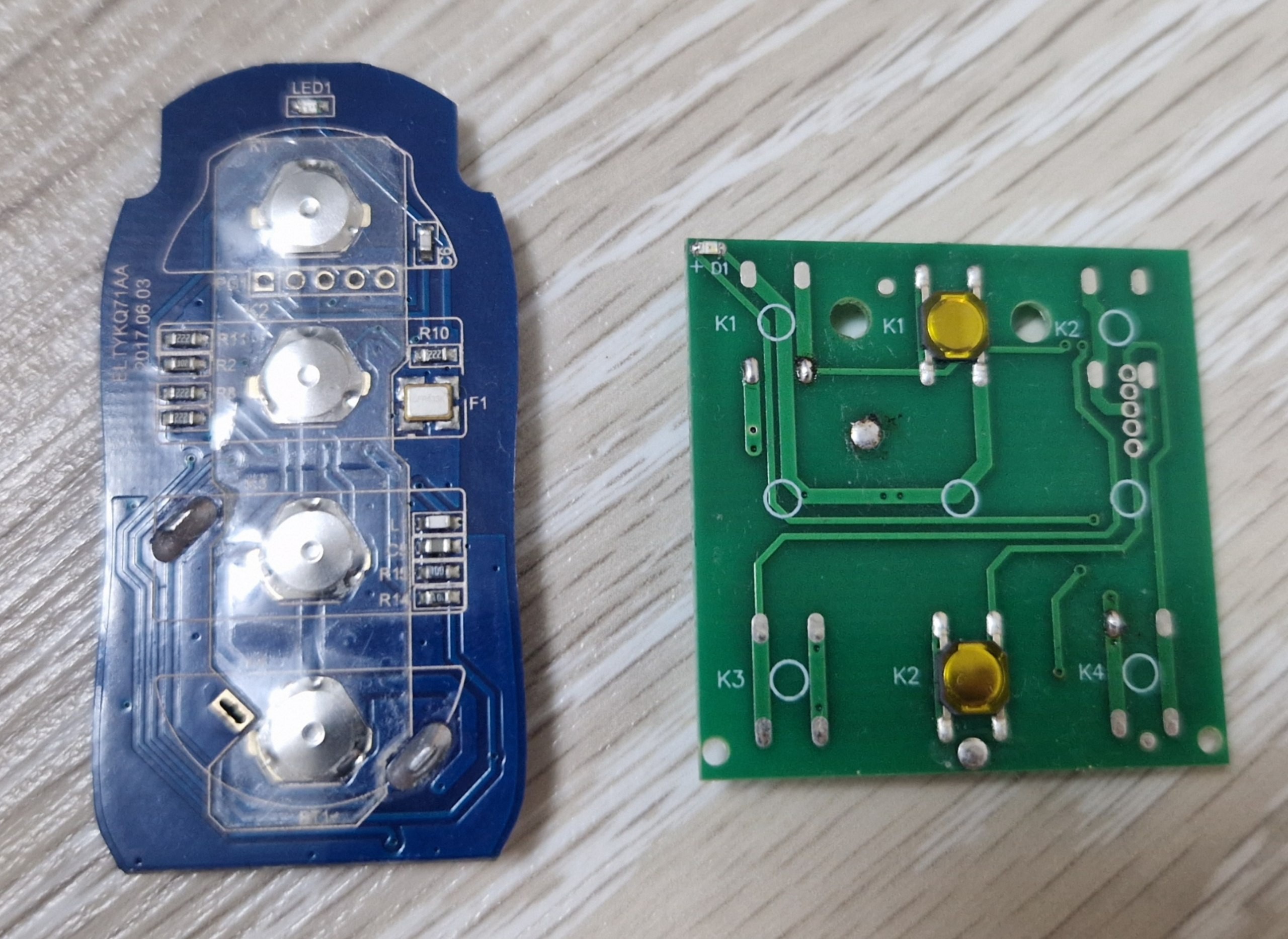
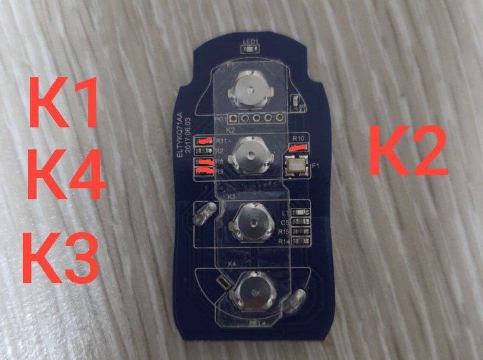
The previous log already describes the firmware's architecture. This one will include a short excerpt of the hardware part. The simple tact buttons usually control the RF remote. As a result, the hardware should be able to click on those buttons by command. Pretty simple, yes? - Not at all!
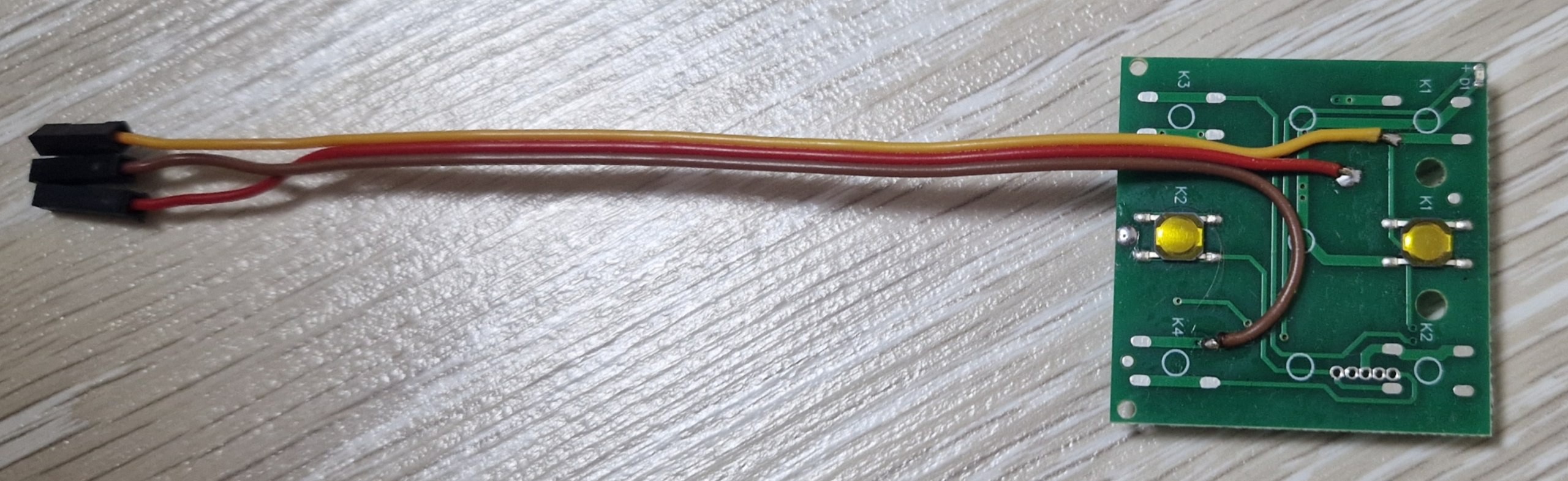
In my case, there are two manufacturers of the remote control: Nice and Alutech.
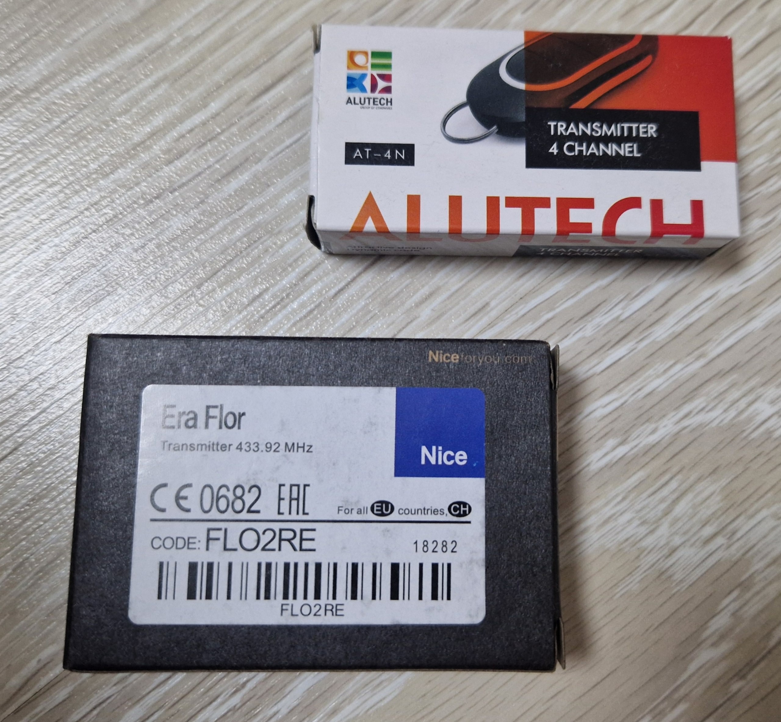
The surprise is that the Nice (a pretty expensive one) remote is literally less technically elegant than the Alutech one. At first view, they are pretty much the same. But the differences are in the power delivery schematic. When Nice`s MCU is all-time powered from the battery directly and is eating it, the Alutech provides the power to the MCU and the RF part only when the button is clicked.
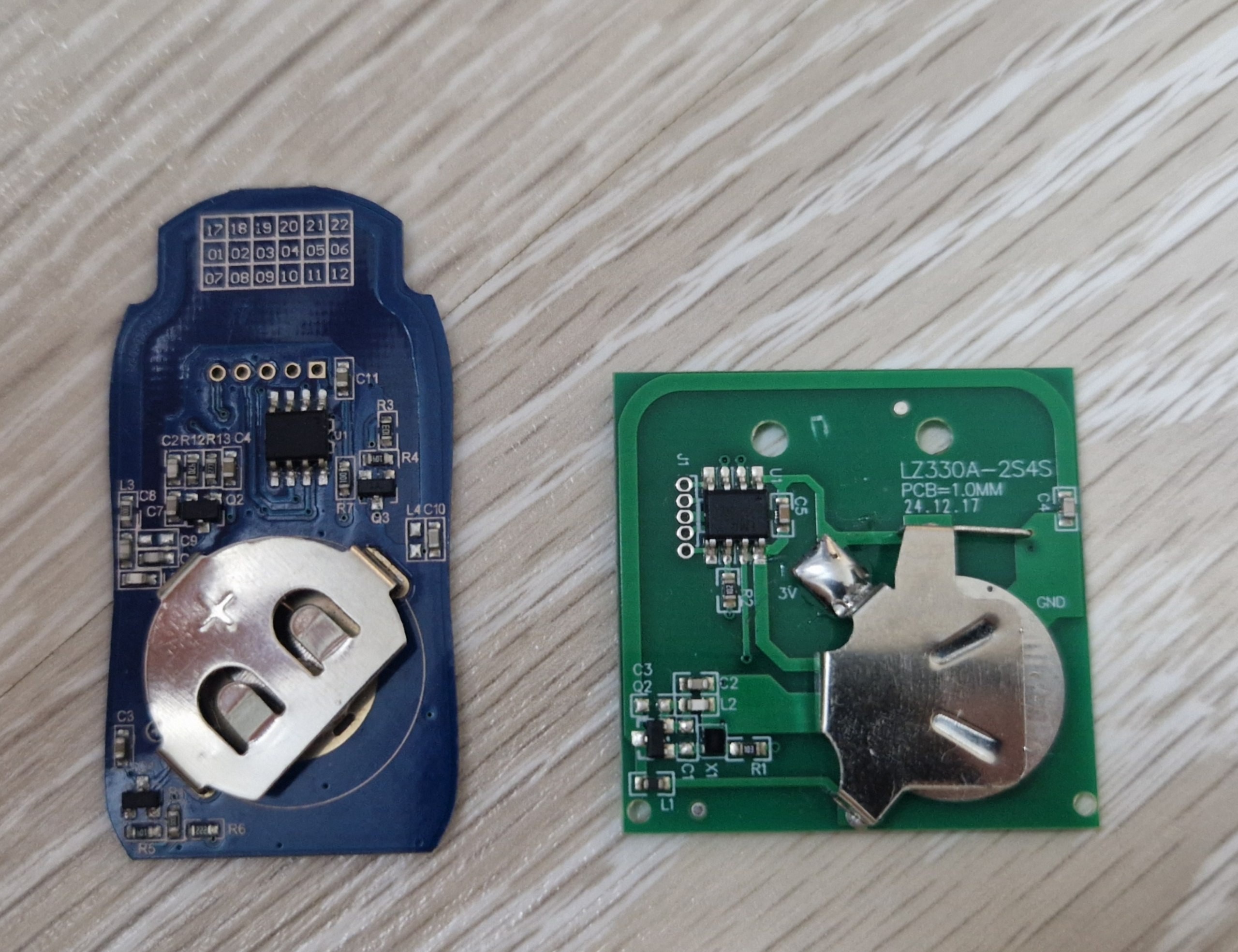
And these technologies from Alutech add some complications. It means that at first, the power to the designated button should be delivered, and then the power to the MCU to activate the transceiving.
In the case of Nice, remote everything is quite simple. The buttons are shortcutting to the GND, and the MCU starts sending the commands. So, its integration was the first one.
And the results:
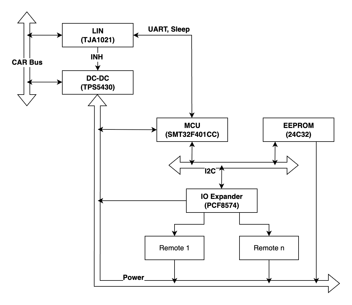
Theoretically, this setup is ready for testing. The hardware part has grown from the start. Now, besides the LIN transmitter and MCU, it also has an EEPROM memory to store the information about the buttons, an IO extender to secure the MCU from any mistakes (and yes, they happen, rest in peace, the previous MCU), and the DC-DC converter that has an important EN input. Somewhy, the VAG engineers decided to power the ECU from the permanent power line. And it means that the device itself should be very efficient when not in use. The LIN transmitter has a built-in possibility to enable power when the LIN gets a wake-up signal. It should be used to control the power of the ECU to be efficient in sleep mode. Also, that output should be reset by the MCU to make it possible to go to the sleep mode of the LIN transmitter. It works like a resettable bit; the activity on the LIN bus sets it HIGH, and the MCU can reset it to floating.
At the start, the "Car" is in sleep mode (11 mA consumption). Then the Light switch wakes up the LIN bus (450 mA consumption), a bit after the "Car" goes back to sleep (25 mA consumption), and then the "garage door opener" goes to sleep too (returning to initial 11 mA consumption).
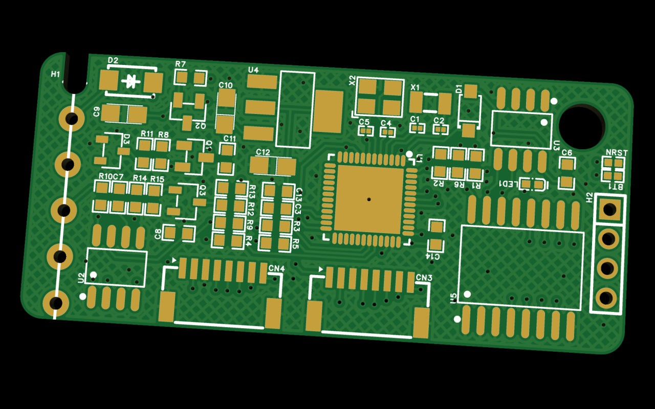
Also, the testing PCB was developed. With pretty large components, and just to test the whole schematic together. The purpose is to repeat the original PCB`s dimensions to reuse the original enclosure.
Discussions
Become a Hackaday.io Member
Create an account to leave a comment. Already have an account? Log In.