 Stepan Skopivskiy
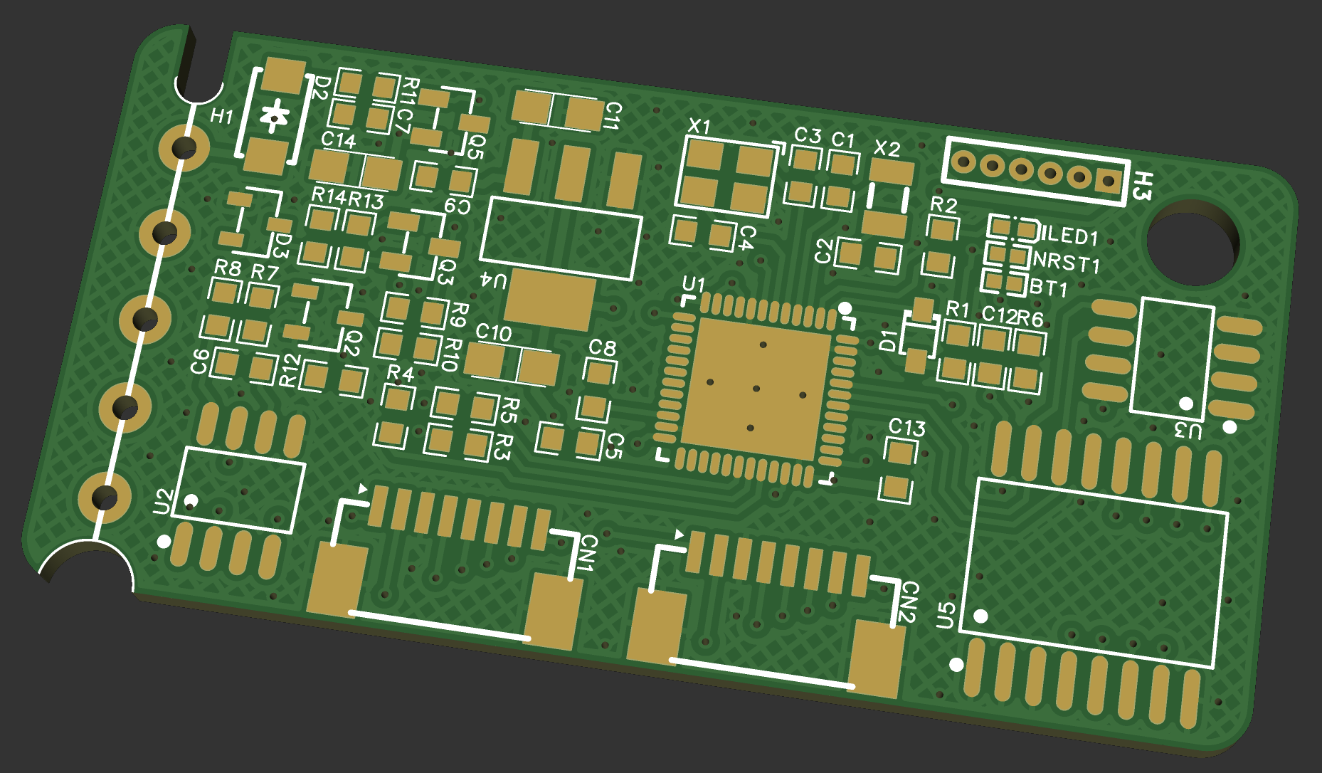
A long time has passed since the last log record. The first version of PCB arrived, and it has been almost successfully soldered. Why almost? - details below.
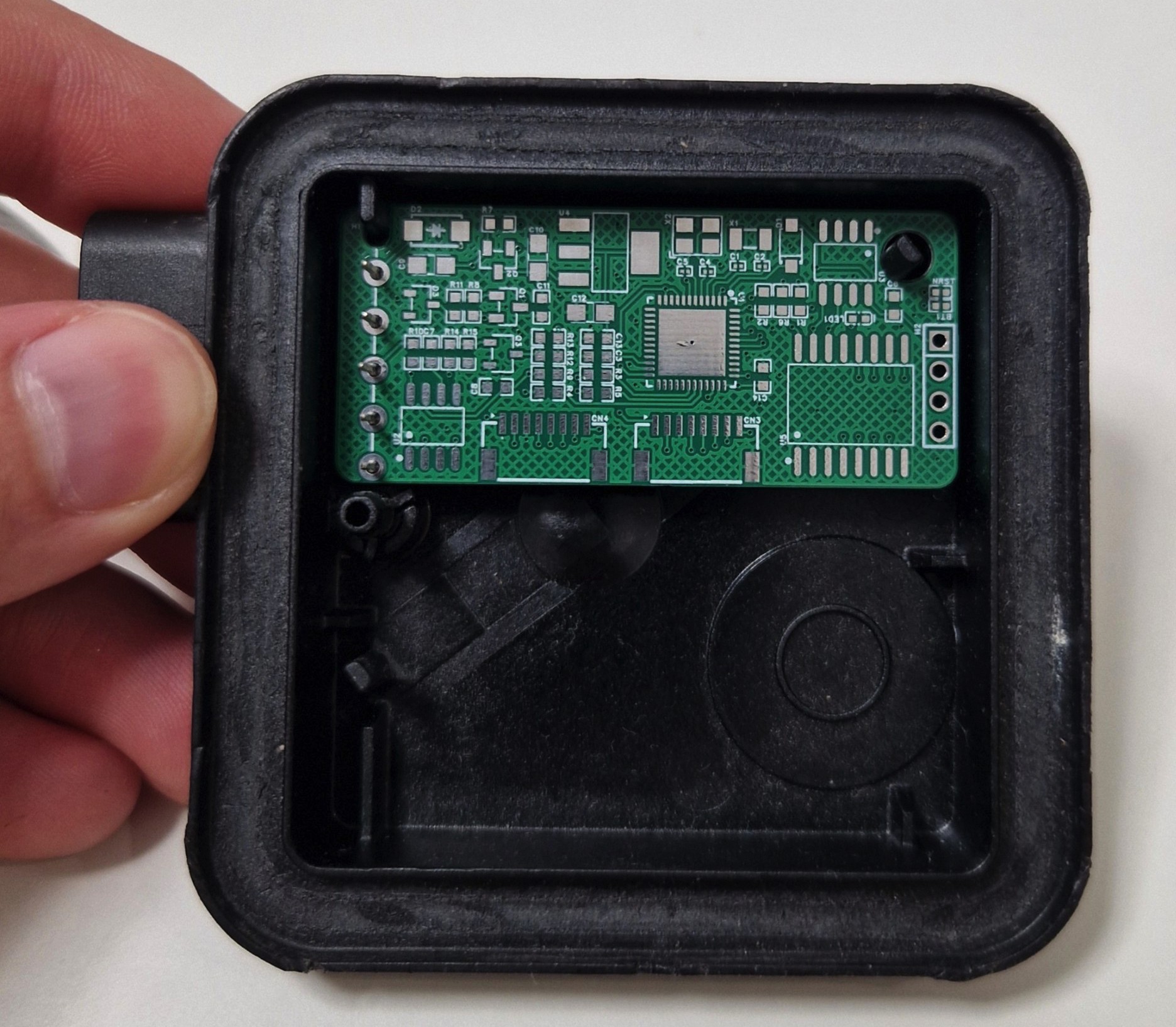
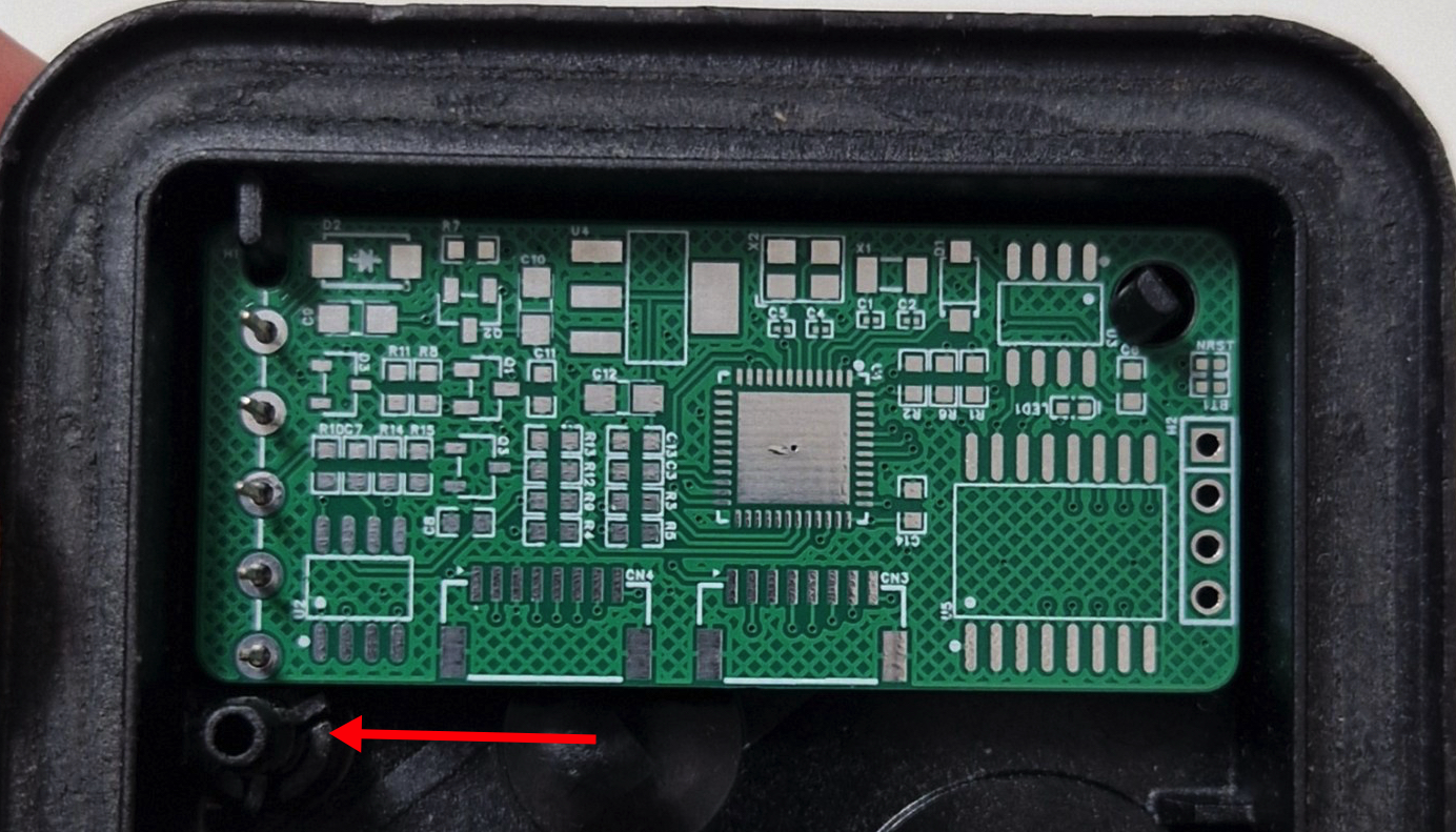
Mistake 1: The PCB is too small. Yes, it is very compact, and it is great, but the other side is that it sways because one of the mounting points was out of the PCB. The fix is simple: just to add at least another millimeter to the PCB height.
Mistake 2: Does not trust the documentation. U(S)ART has 2 pins - TX and RX. And usually, if two devices should communicate with each other, the connection is vice versa: TX<>RX.
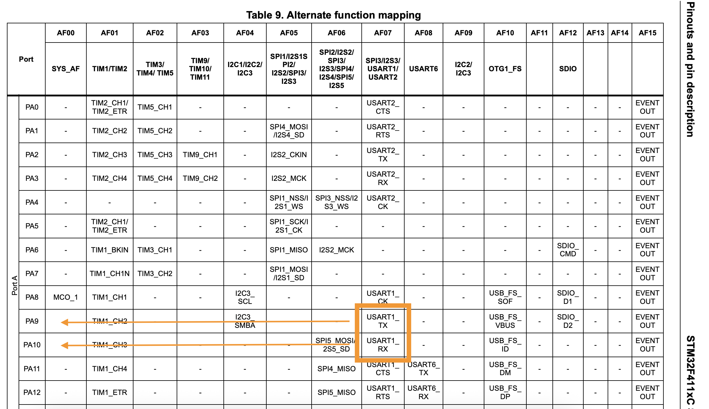
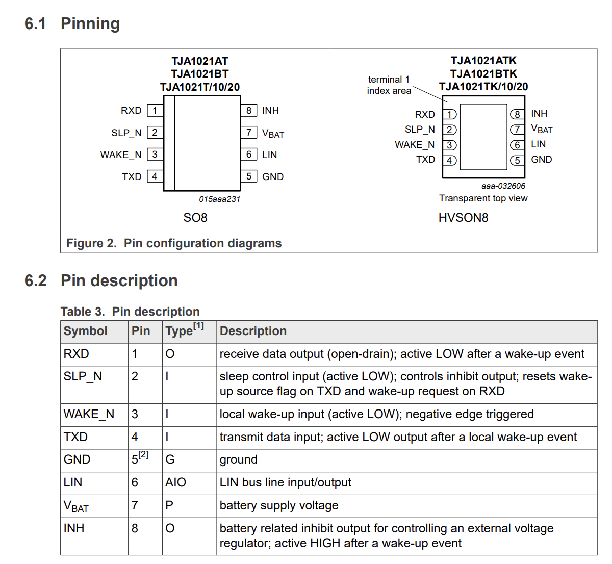
So, should the connection be the next: PA9 - RXD Pin 1; PA10 - TXD Pin 4?
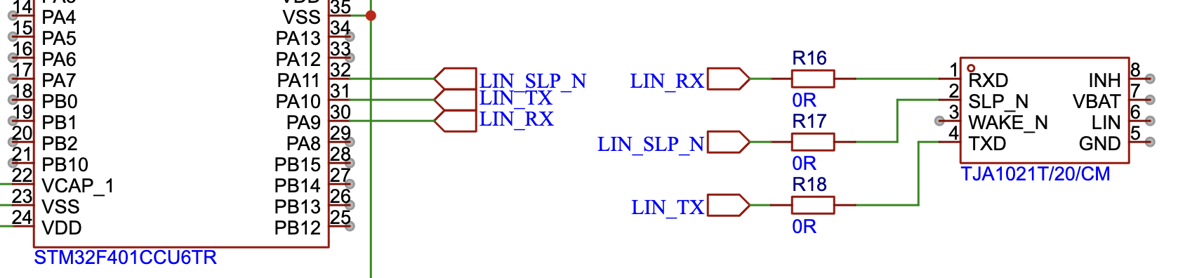
No! It should not! Maybe I was blind or did not understand the electronics, but all my previous experience was based on crossing the documented TX and RX pins. Thankfully to the dumping resistors, the fix is simple too: just do another crossing.
Always add damping resistors in your signal lines — it’s simply good PCB design practice.
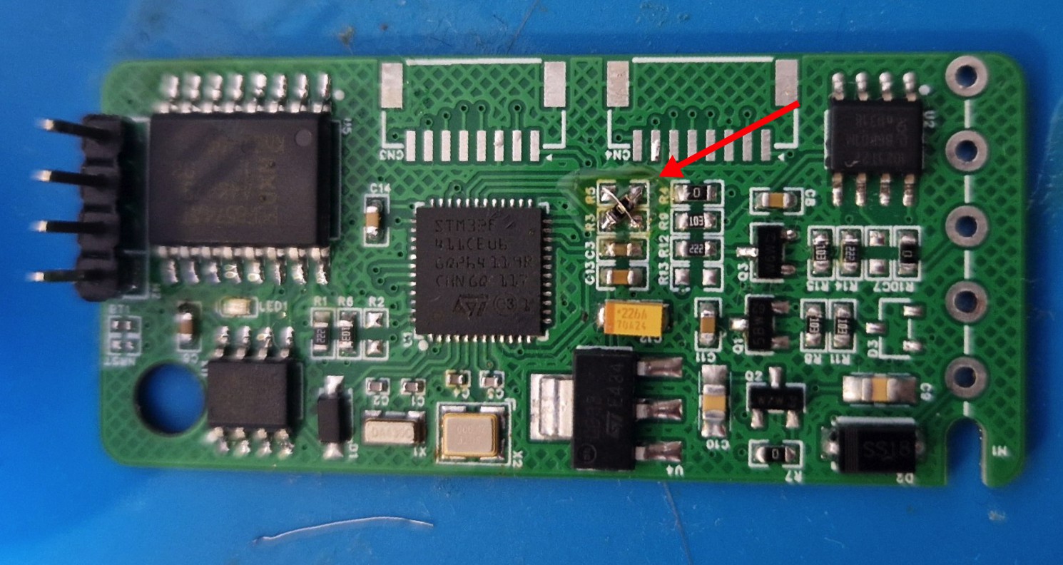
Mistake 3: The boot pins need LOW, not HIGH. It was one of the reasons why the flushing was falling (the removed R2 on PCB).
Mistake 4: Compex does not mean reliable, especially if it relates to the analog part of the schematic. The original ECU uses a pretty complex schematic based on bipolar transistors to manage the VBAT line. It combines the power management from the LIN receiver and the MCU, as well as limiting the input voltage of the LDO converter to avoid reaching its maximum level, as the car can produce various voltages in its onboard VBAT line.
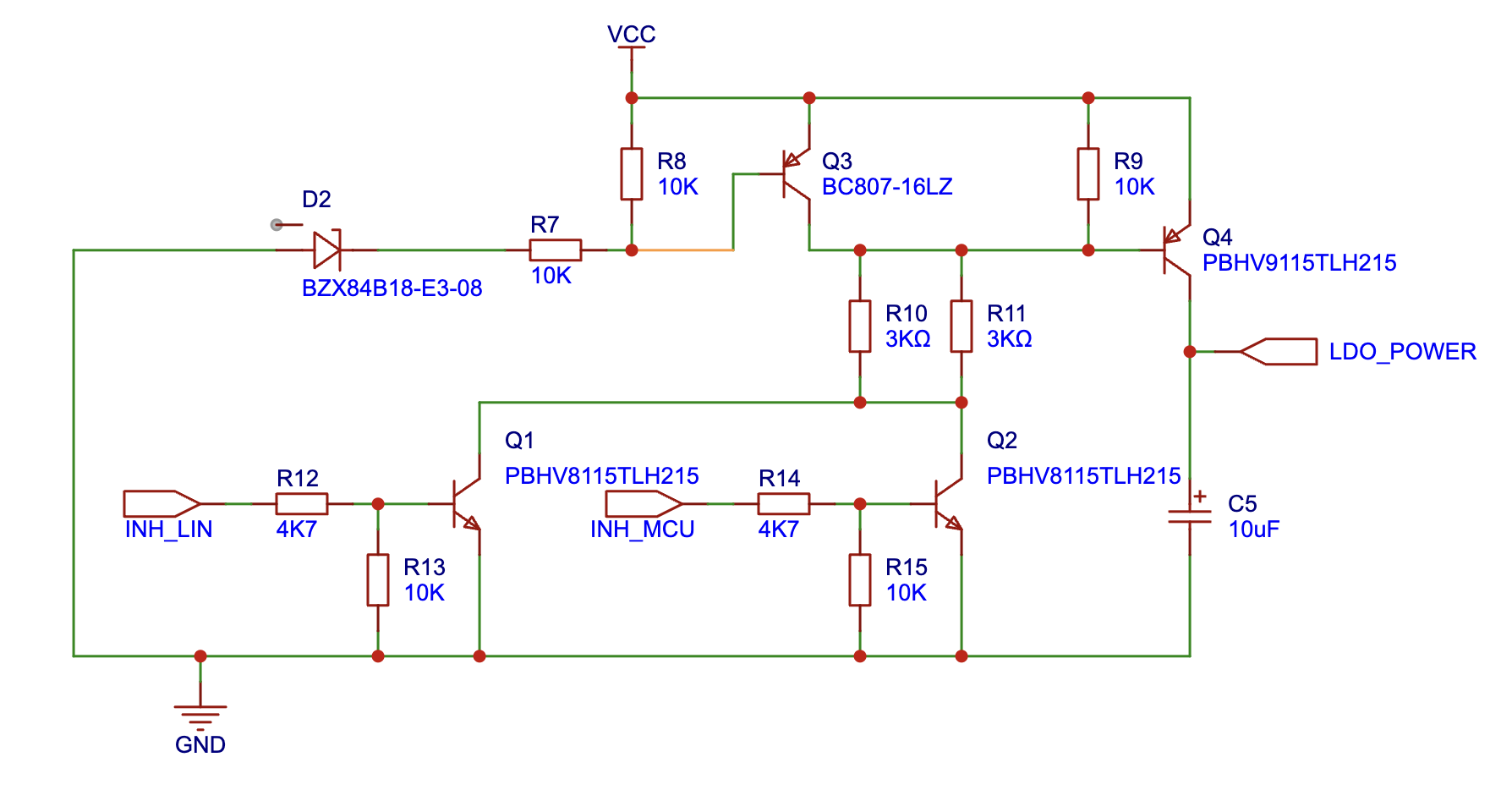
However, the bipolar transistors are controlled by current, which means that they are very sensitive to the current on their Base and the end power consumption. Besides that, different transistors have different multiplier characteristics. As a result, the "full Open" does not mean good here, as the also means a wasting of power on the transistor base. As well as a "half Open" too, because in that case transistors become a resistor which is heating it with each mA passed through themself. The original components are rare as they are automotive-specific, but they are still achievable, at least. Waiting a long time does not make any sense; the particular transistors were replaced with ones that are more popular and common. Of course, without any recalculations of the resistors.
The result is around 40mA and the heating of components. After a few attempts to guess the values of the resistors, the only correct decision was made - replace the main switch with the P-channel MOSFET and the inverting transistor with a very popular 2N2222. Unlike the bipolar, the FET is controlled by voltage, which means that it almost does not require strict calculation, as it opens when the necessary voltage is reached. ChatGPT helped to calculate (guess) the approximate resistor values. Now the result is promising: 25mA consumption with no heating at all. Except for the common heating on the LDO voltage regulator, which is normal.
Mistake 5: The 0.2mm line width is too small for power lines. The first PCB was never suggested as a production one and was made just to test all the components together in real life. It instantly causes a problem with flashing because of a weak power supply. The fix was tricky, adding another line of ground touched in the diagonal of the flashing header minimized the frequency, but does not solve it totally.
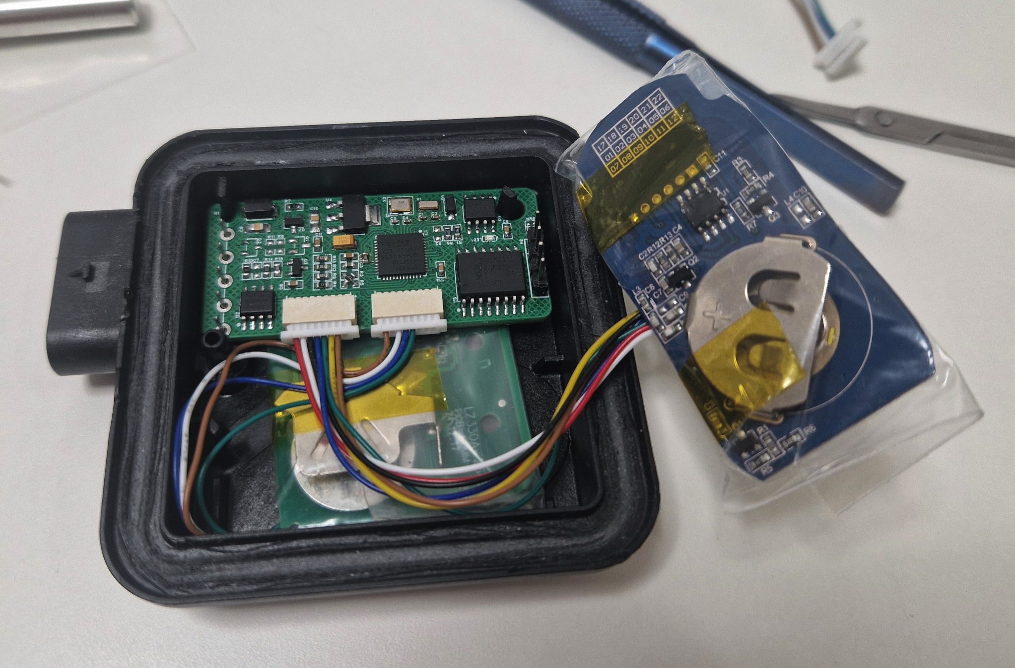
At this time, the device was ready to insert it into the car for some real testing. The car accepted it as its own. Everything works fine except for some strange blinking of the button when the car is near the programmed GPS position of the button.
Mistake 6: The wrong BAP function ID. The blinking of the button was related to the wrong function id during heart beat reporting. The sync status was reported as an operation status. So, MMI was redrawing the button each time the status was changed.
Mistake 7: The memory collision: KISS (Keep it simple, stupid). To avoid blocking the BAP messages processing, the additional layer of memory management was orginazed throu the FreeRTOS tasks. But it was definitely an overcomplication and caused an issue when more the one button needed to be saved. For example, deleting 2 or more buttons had the effect of deleting just the first one only.
Conclusion: The test was totally successful, and it highlighted numerous mistakes that were fixed in the next revision of the PCB and Software.
Discussions
Become a Hackaday.io Member
Create an account to leave a comment. Already have an account? Log In.