Close
0%
0%

Handheld PONG Console

Made a small DIY Pong Game console from scratch.

Similar projects worth following
0 followers
Greetings everyone and welcome back! This is Pong PRO, a homemade mini-game device that runs PONG.
Here, we're running PONG on an ESP32 Dev board with an SSD1306 OLED screen and controlling the bar with two directional buttons. Everything is then fixed in unique 3D-printed grips, allowing the user to properly operate the controller.

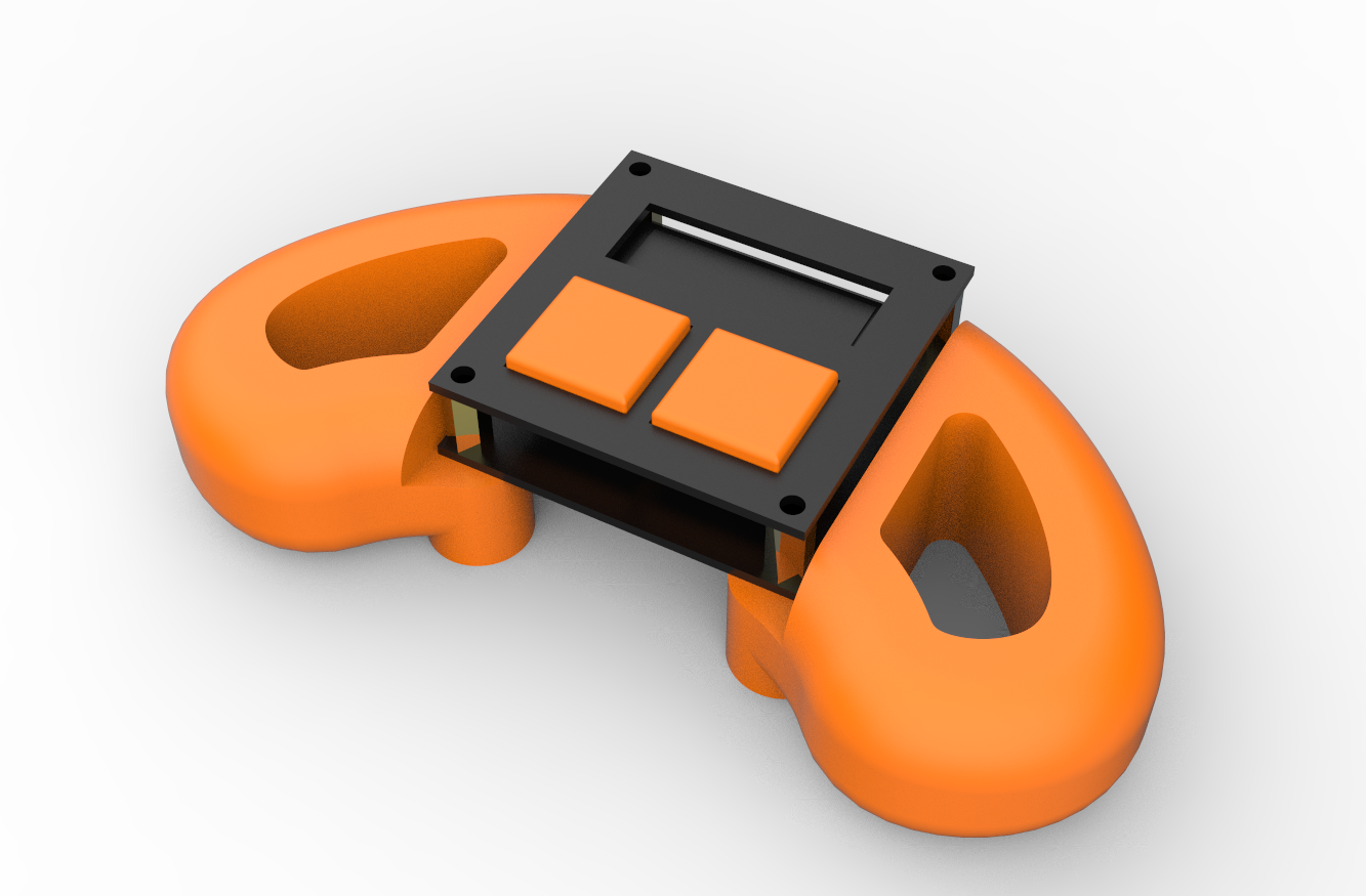
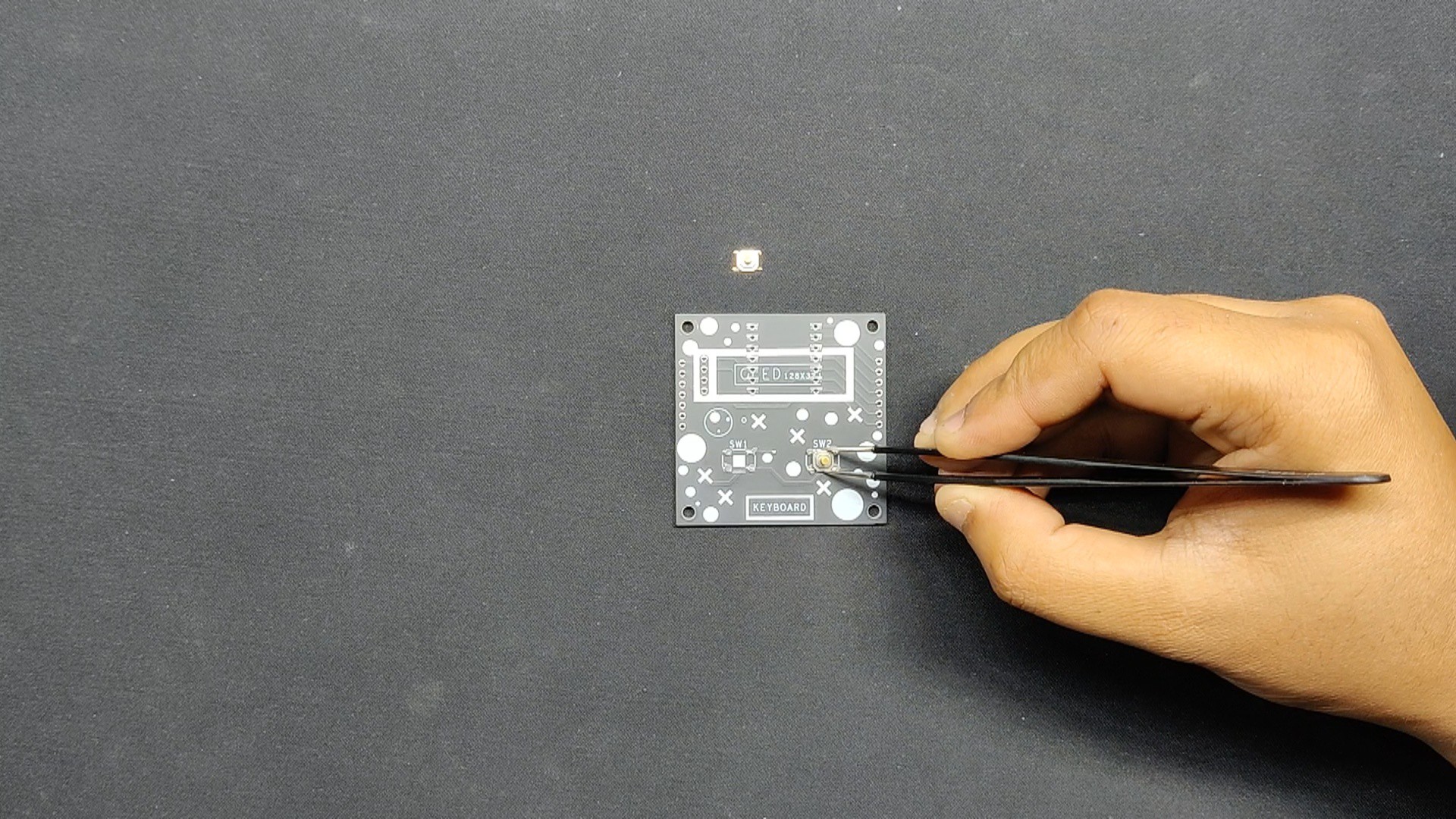
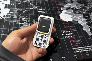
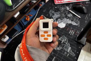
This project is based on our previous Macropad project's PCBs, which is essentially an ESP32 breakout with two buttons attached to the microcontroller and a 124x32 OLED display. Modeled two handles and transformed the project into a fully functional PONG gaming console.

3D Model

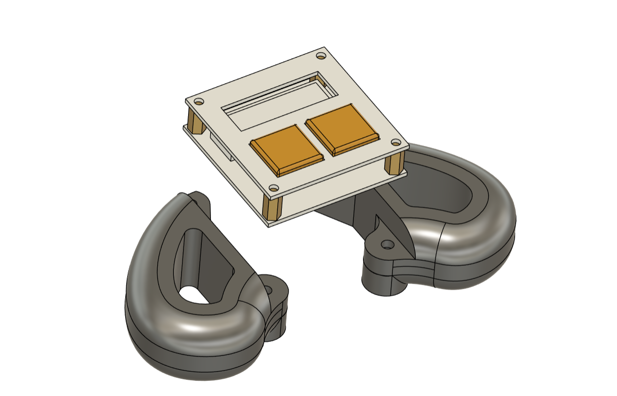
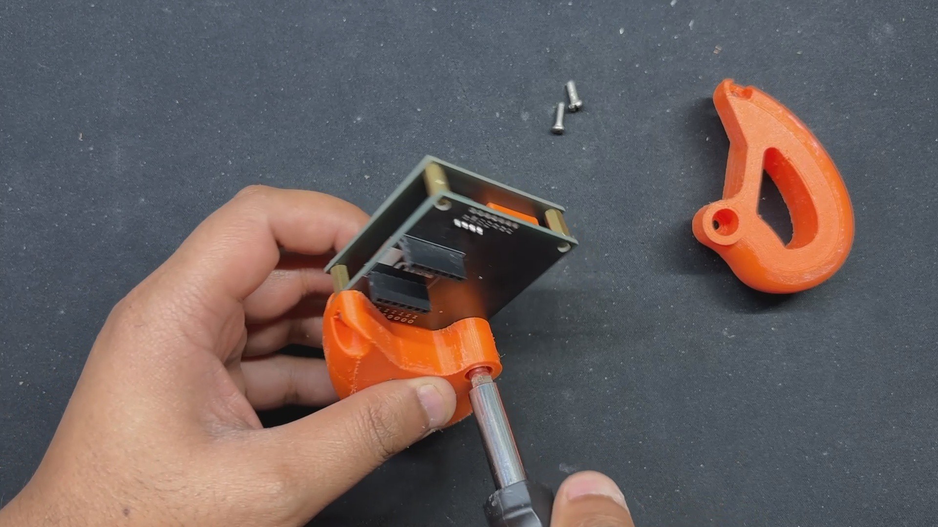
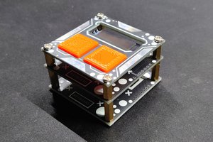
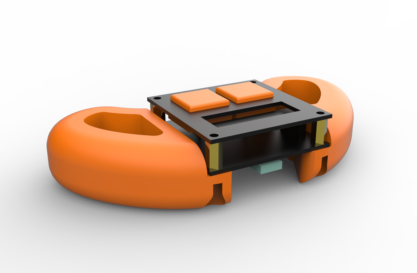
The 3D model of this project consists of the original Macropad Assembly, which is made up of three layers: the top layer, the middle layer, and the bottom layer, all of which are joined together by M2.5 PCB standoffs. For this design, we deleted the bottom layer and just kept the top and middle layers.

The middle layer holds all of the electronics components, which include the ESP32 microcontroller board, an SSD1306 OLED screen, and two SMD push buttons. The top layer serves as an aesthetic cover for the midlayer, which has three openings: one rectangular aperture for the OLED display and two switch actuators.

The switch actuators are modeled and positioned between the top layer's switch opening slots and the SMD switch knob.

Because the switch actuator and switch knob are positioned perfectly on top of each other, squeezing the switch actuator also presses the knob, resulting in a switch click.

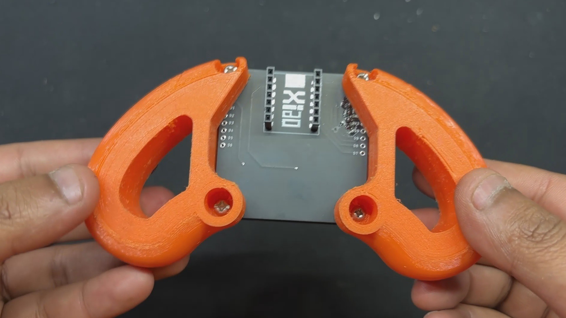
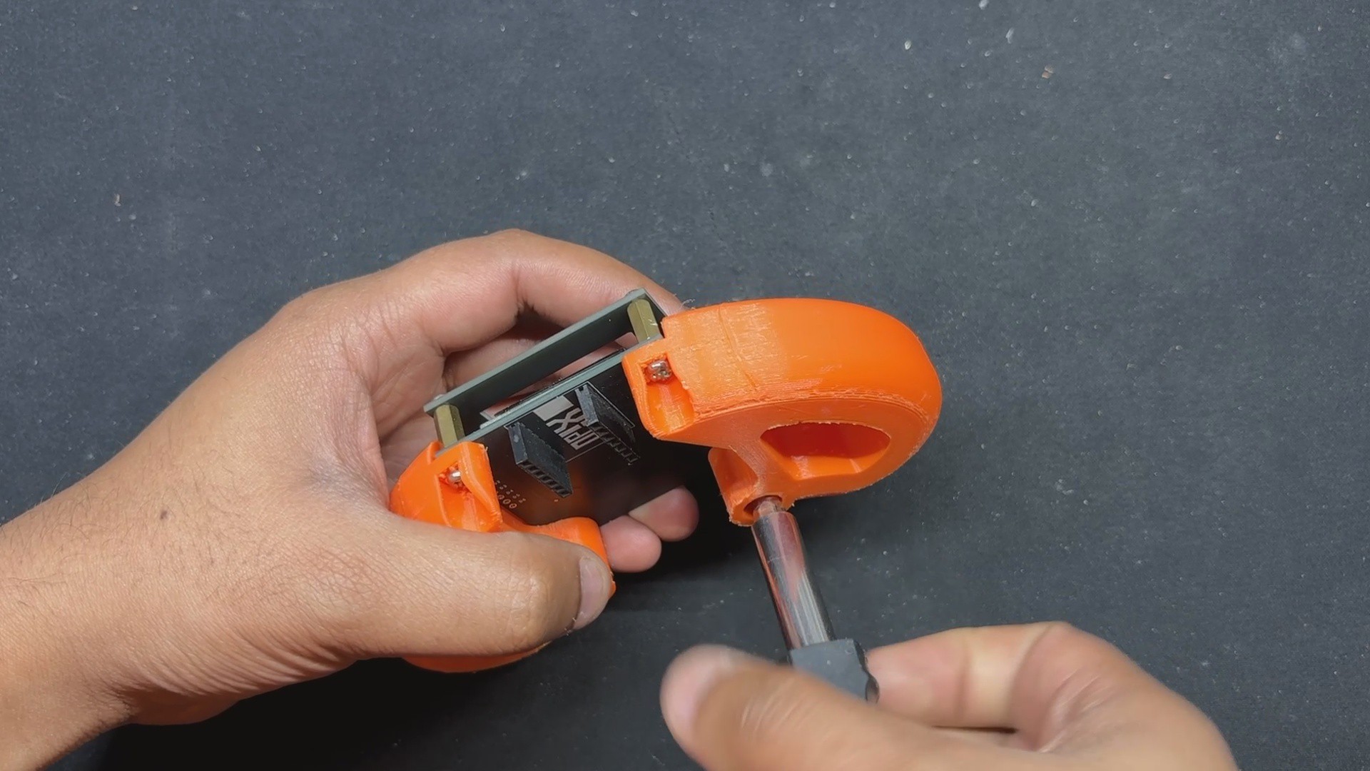
To hold this console ergonomically, we took inspiration from the Sega Genesis Controller and designed two grip parts secured using M2.5 PCB standoffs used to connect the two PCB layers.

After finishing the model, the switch actuators and handgrip were exported as mesh files and 3D printed with orange PLA and a 0.4mm nozzle.

PCB Design

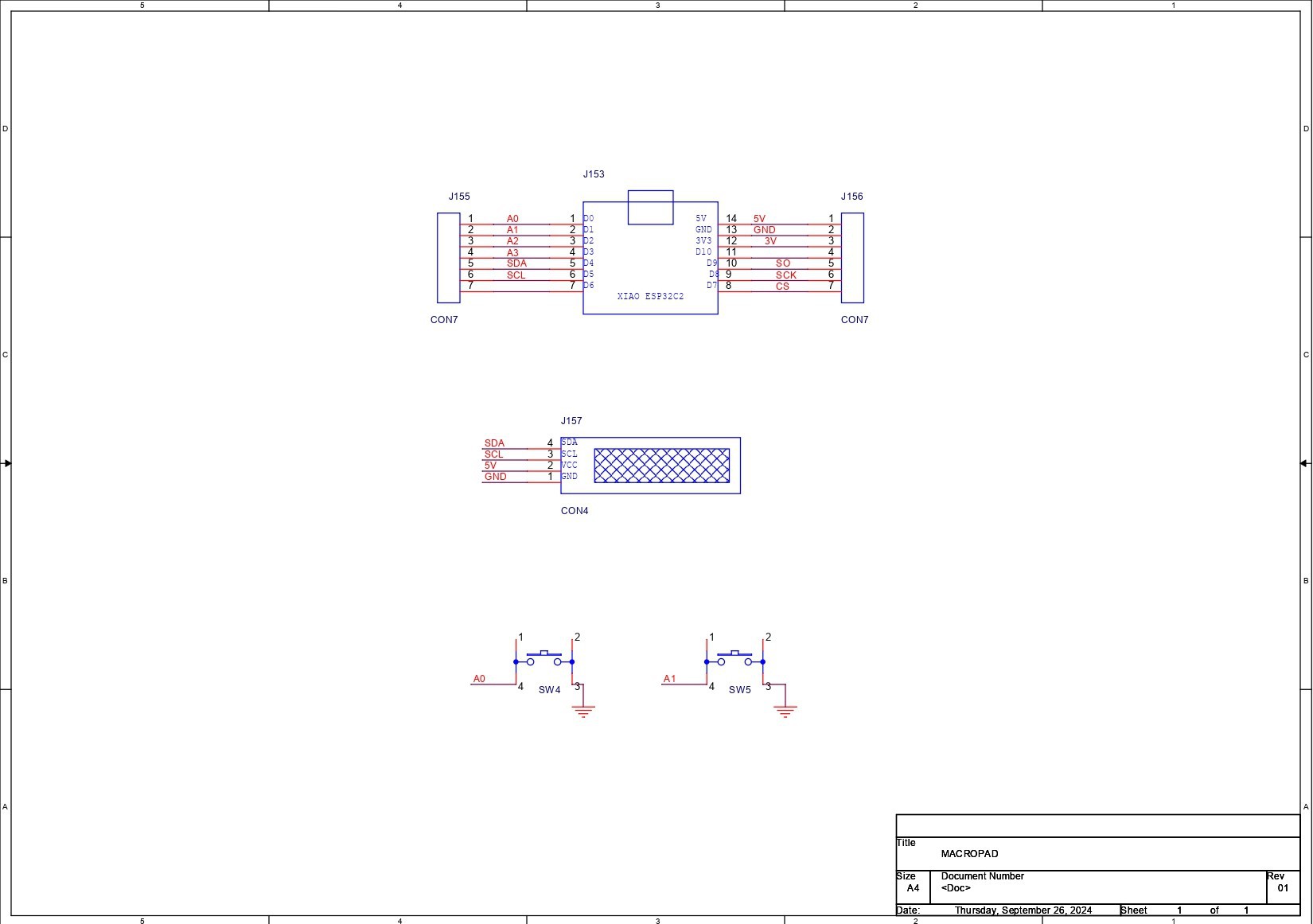
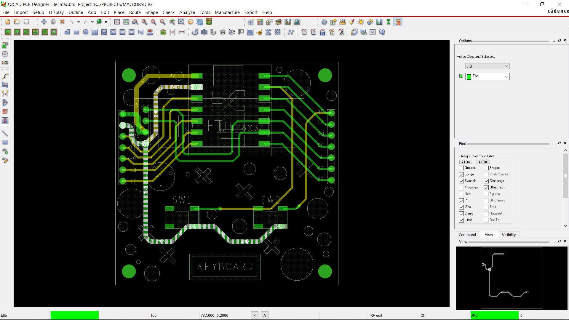
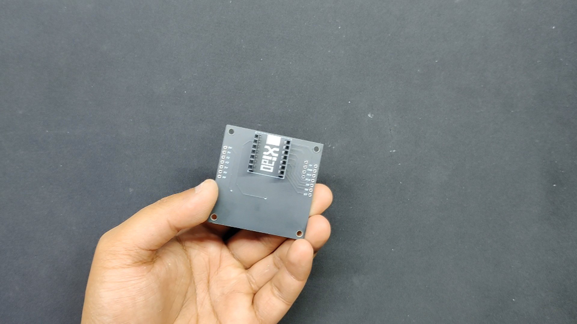
The PCB design for this project was straightforward; we utilized an XIAO ESP32 board with D0 and D1 I/O pins to connect it to two SMD switches. We also combined an OLED display with the microcontroller, which is connected to the XIAO's I2C ports.

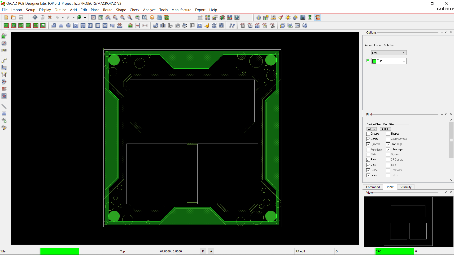
We created two boards based on the model's dimensions: the top layer board and the middle layer board. Because the midlayer board and the bottom layer share the same form and mounting holes, we will use it for the bottom layer.

HQ NextPCB Service

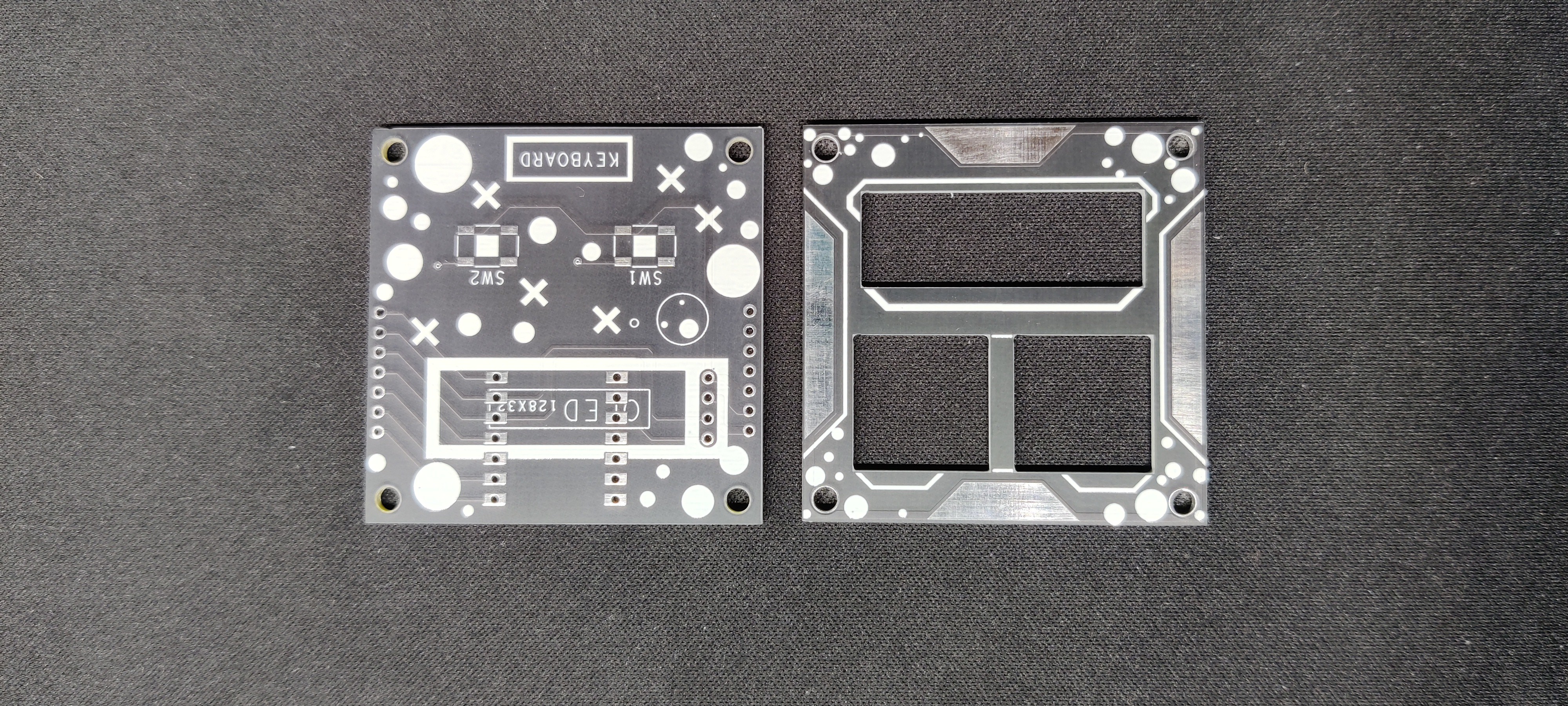
After completing the PCB design, we export the Gerber data and send it to HQ NextPCB for samples.

For the mid and top layer boards, two orders were placed. We ordered a black Solder mask with white screen for the mid- and top-layer boards.

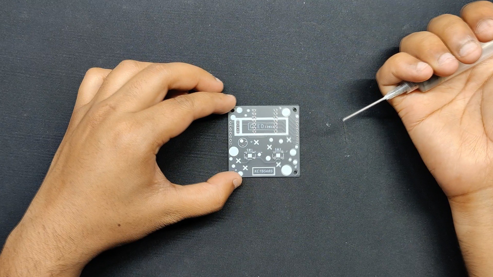
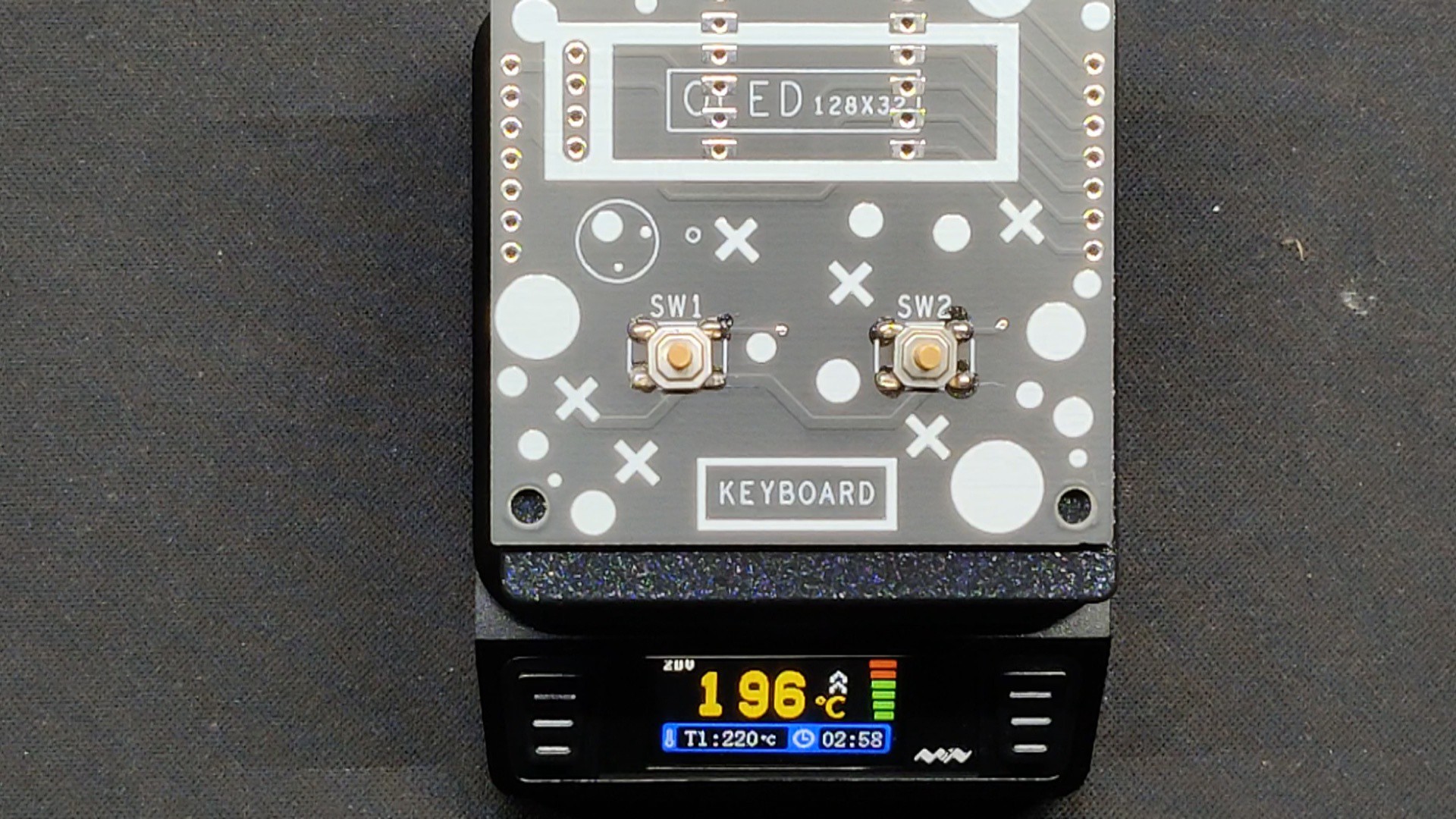
After placing the order, the PCBs were received within a week, and the PCB quality was pretty great.

In addition, I have to bring in HQDFM to you, which helped me a lot through many projects. Huaqiu’s in-house engineers developed the free Design for Manufacturing software, HQDFM, revolutionizing how PCB designers visualize and verify their designs.

Take advantage of NextPCB's Accelerator campaign and get 2 free assembled RP2040-based PCBs for your innovative projects.

https://www.nextpcb.com/blog/rp2040-free-pcba-prototypes-nextpcb-accelerator

This offer covers all costs, including logistics, making it easier and more affordable to bring your ideas to life. SMT services can be expensive, but NextPCB is here to help you overcome that hurdle. Simply share your relevant project, and they'll take care of the rest. Don't miss out on this amazing opportunity to advance your tech creations!

HQDFM: Free Online Gerber Viewer and DFM Analysis Tool

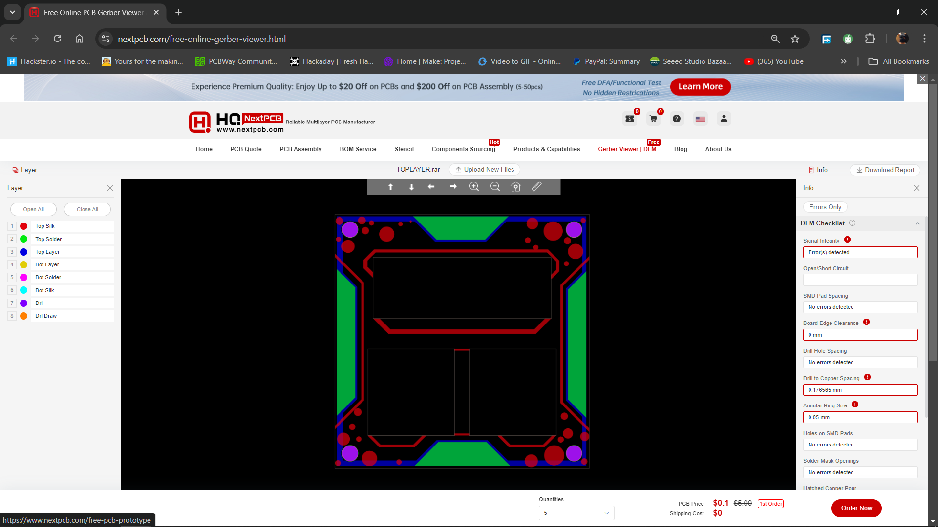
Also, NextPCB has its own Gerber Viewer and DFM analysis software.

Your designs are improved by their HQDFM software (DFM) services. Since I find it annoying to have to wait around for DFM reports from manufacturers, HQDFM Is the most efficient method for performing a pre-event self-check.

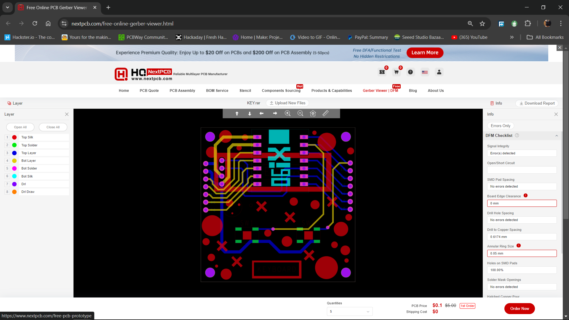
Here is what online Gerber Viewer shows me. Would not be more clear. However, for full function, like DFM analysis for PCBA, you need to download the software. The online version only provides a simple PCB DFM report.

With comprehensive Design for Manufacture (DFM) analysis features, HQDFM Is a free, sophisticated online PCB Gerber file viewer.

It provides insights into advanced manufacturing by utilizing over 15 years of industry expertise. You guys can check...

Read more »

  • 1
    PCB Assembly
    • Using a solder paste dispenser needle, we begin the PCB assembly process by putting solder paste on each component pad.
    • Next, we pick and place the SMD Switch in its location using an ESD Tweezer.
    • Subsequently, we remove the board and set it on our Reflow Hotplate, which raises the PCB's temperature from below to the point at which the solder paste melts and the SMD components are all connected to their pads.
    • We attached the pads of the two CON7 Female Header Pin connectors that we inserted from the back side of the PCB to the location of the XIAO Microcontroller.
    • We soldered the OLED into place after adding it from the top side.

    Board assembly is now complete.

  • 2
    Console Assembly
    • Connecting the 9mm PCB standoffs to the top layer of the board via its four mounting holes is how we begin the layer assembly procedure.
    • The top layer board was flipped, and the two 3D-printed switches were inserted into their designated slots.
    • Next, the midlayer was positioned from the bottom of the top layer.
    • We then placed 3D-printed left and right handgrips over the midlayer and secured them with two M2.5 screws to the PCB standoffs.
    • After attaching both handhrips to the standoffs that connect the top and middle layers of the PCB, we installed the XIAO ESP32 and completed our console assembly.
  • 3
    CODE

    Let's have a look at the code we built, and its a simple one.

    #include <Wire.h>
    #include <Adafruit_GFX.h>
    #include <Adafruit_SSD1306.h>
    
    #define SCREEN_WIDTH 128
    #define SCREEN_HEIGHT 32
    #define OLED_RESET    -1
    Adafruit_SSD1306 display(SCREEN_WIDTH, SCREEN_HEIGHT, &Wire, OLED_RESET);
    
    const int buttonUpPin = 1; // Pin for the up button
    const int buttonDownPin = 0; // Pin for the down button
    
    const int paddleHeight = 12;
    const int paddleWidth = 3;
    int playerPaddleY = (SCREEN_HEIGHT - paddleHeight) / 2;
    int compPaddleY = (SCREEN_HEIGHT - paddleHeight) / 2;
    
    int ballX = SCREEN_WIDTH / 2;
    int ballY = SCREEN_HEIGHT / 2;
    int ballVelocityX = 2;
    int ballVelocityY = 2;
    
    bool isGameOver = false;
    bool playerWin = false;
    
    void setup() {
      if (!display.begin(SSD1306_SWITCHCAPVCC, 0x3C)) {
        Serial.println(F("SSD1306 allocation failed"));
        for (;;);
      }
      // Clear the Adafruit splash screen
      display.clearDisplay();
      display.display();
      delay(2000);
    
      // Display the welcome screen
      display.setTextSize(2);
      display.setTextColor(SSD1306_WHITE);
      display.setCursor(10, 10);
      display.print("PONG PRO");
      display.display();
      delay(2000);
    
      pinMode(buttonUpPin, INPUT_PULLUP);
      pinMode(buttonDownPin, INPUT_PULLUP);
    }
    
    void loop() {
      if (isGameOver) {
        display.clearDisplay();
        display.setTextSize(2);
        display.setTextColor(SSD1306_WHITE);
        display.setCursor((SCREEN_WIDTH - 72) / 2, (SCREEN_HEIGHT - 16) / 2);
        if (playerWin) {
          display.print("You Win!");
        } else {
          display.print("You Lose!");
        }
        display.display();
        delay(3000);
        isGameOver = false;
        ballX = SCREEN_WIDTH / 2;
        ballY = SCREEN_HEIGHT / 2;
        playerPaddleY = (SCREEN_HEIGHT - paddleHeight) / 2;
        compPaddleY = (SCREEN_HEIGHT - paddleHeight) / 2;
        return;
      }
    
      // Update player paddle position
      if (digitalRead(buttonUpPin) == LOW) {
        playerPaddleY = max(playerPaddleY - 1, 0);
      }
      if (digitalRead(buttonDownPin) == LOW) {
        playerPaddleY = min(playerPaddleY + 1, SCREEN_HEIGHT - paddleHeight);
      }
    
      // Update computer paddle position
      if (ballY < compPaddleY + paddleHeight / 2) {
        compPaddleY = max(compPaddleY - 1, 0);
      }
      if (ballY > compPaddleY + paddleHeight / 2) {
        compPaddleY = min(compPaddleY + 1, SCREEN_HEIGHT - paddleHeight);
      }
    
      // Update ball position
      ballX += ballVelocityX;
      ballY += ballVelocityY;
    
      // Check ball collisions with top and bottom
      if (ballY <= 0 || ballY >= SCREEN_HEIGHT - 1) {
        ballVelocityY = -ballVelocityY;
      }
    
      // Check ball collision with player paddle
      if (ballX <= paddleWidth && ballY >= playerPaddleY && ballY <= playerPaddleY + paddleHeight) {
        ballVelocityX = -ballVelocityX;
      }
    
      // Check ball collision with computer paddle
      if (ballX >= SCREEN_WIDTH - paddleWidth - 1 && ballY >= compPaddleY && ballY <= compPaddleY + paddleHeight) {
        ballVelocityX = -ballVelocityX;
      }
    
      // Check ball out of bounds
      if (ballX <= 0) {
        isGameOver = true;
        playerWin = false;
      }
      if (ballX >= SCREEN_WIDTH - 1) {
        isGameOver = true;
        playerWin = true;
      }
    
      // Clear display
      display.clearDisplay();
    
      // Draw player paddle
      display.fillRect(0, playerPaddleY, paddleWidth, paddleHeight, SSD1306_WHITE);
    
      // Draw computer paddle
      display.fillRect(SCREEN_WIDTH - paddleWidth, compPaddleY, paddleWidth, paddleHeight, SSD1306_WHITE);
    
      // Draw ball
      display.fillRect(ballX, ballY, 1, 1, SSD1306_WHITE);
    
      // Update display
      display.display();
    
      delay(30);
    }

    we are using two buttons to control the paddle. It includes initialization for the display and buttons, variables to track the paddle and ball positions, and game logic to handle ball movement, paddle control, and collision detection.

    The game starts with a "PONG PRO" welcome screen and shows "You Win!" or "You Lose!" messages when the game ends, depending on whether the player or the computer missed the ball. The game then resets for another round, continuing in a loop until the device is turned off.

View all 4 instructions

Enjoy this project?

Share

Discussions

Similar Projects

Does this project spark your interest?

Become a member to follow this project and never miss any updates