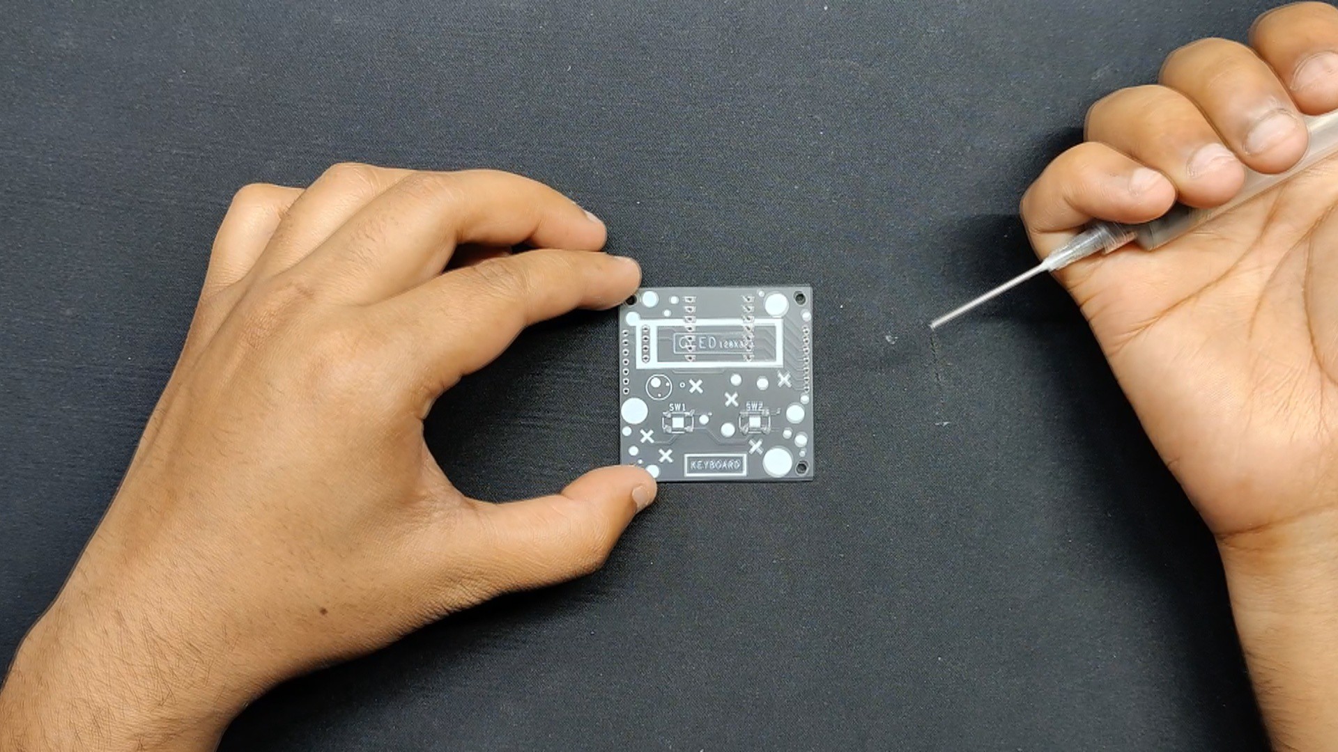
Using a solder paste dispenser needle, we begin the PCB assembly process by putting solder paste on each component pad.
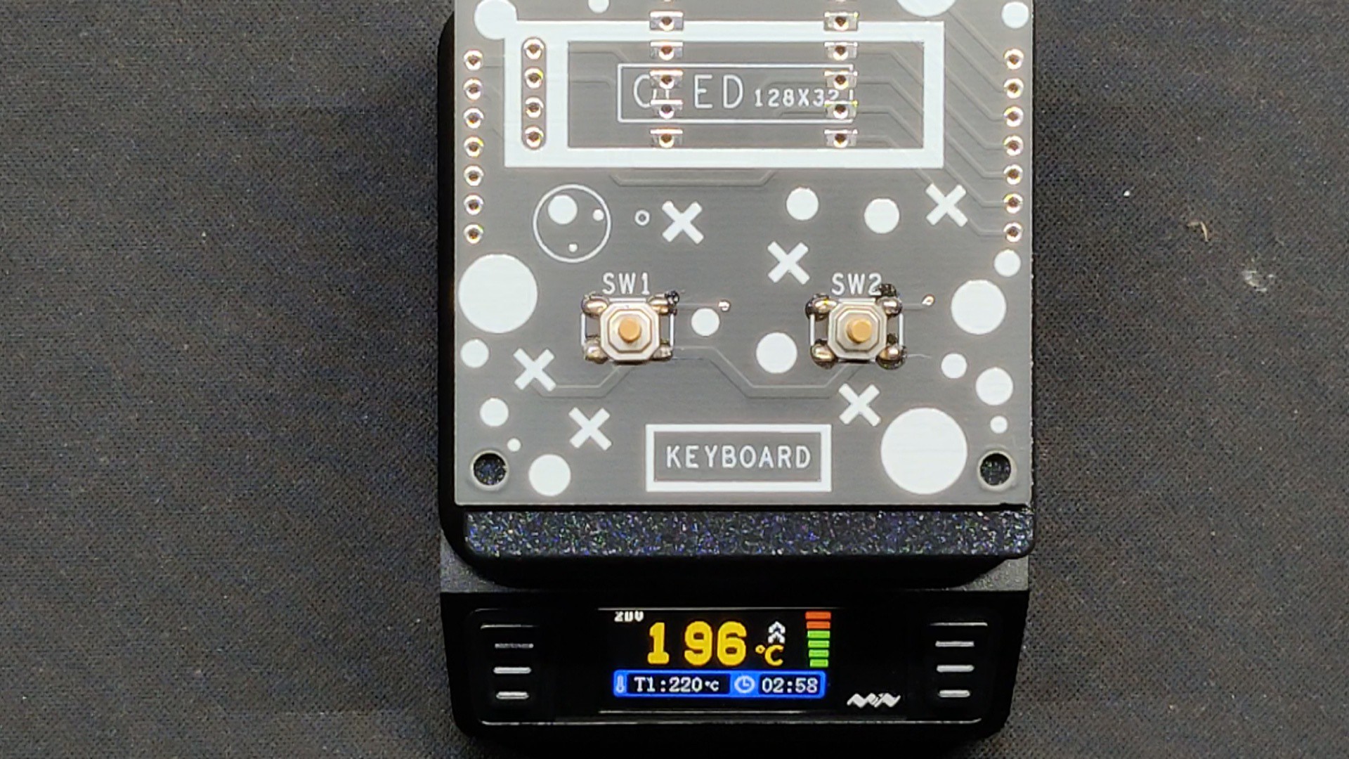
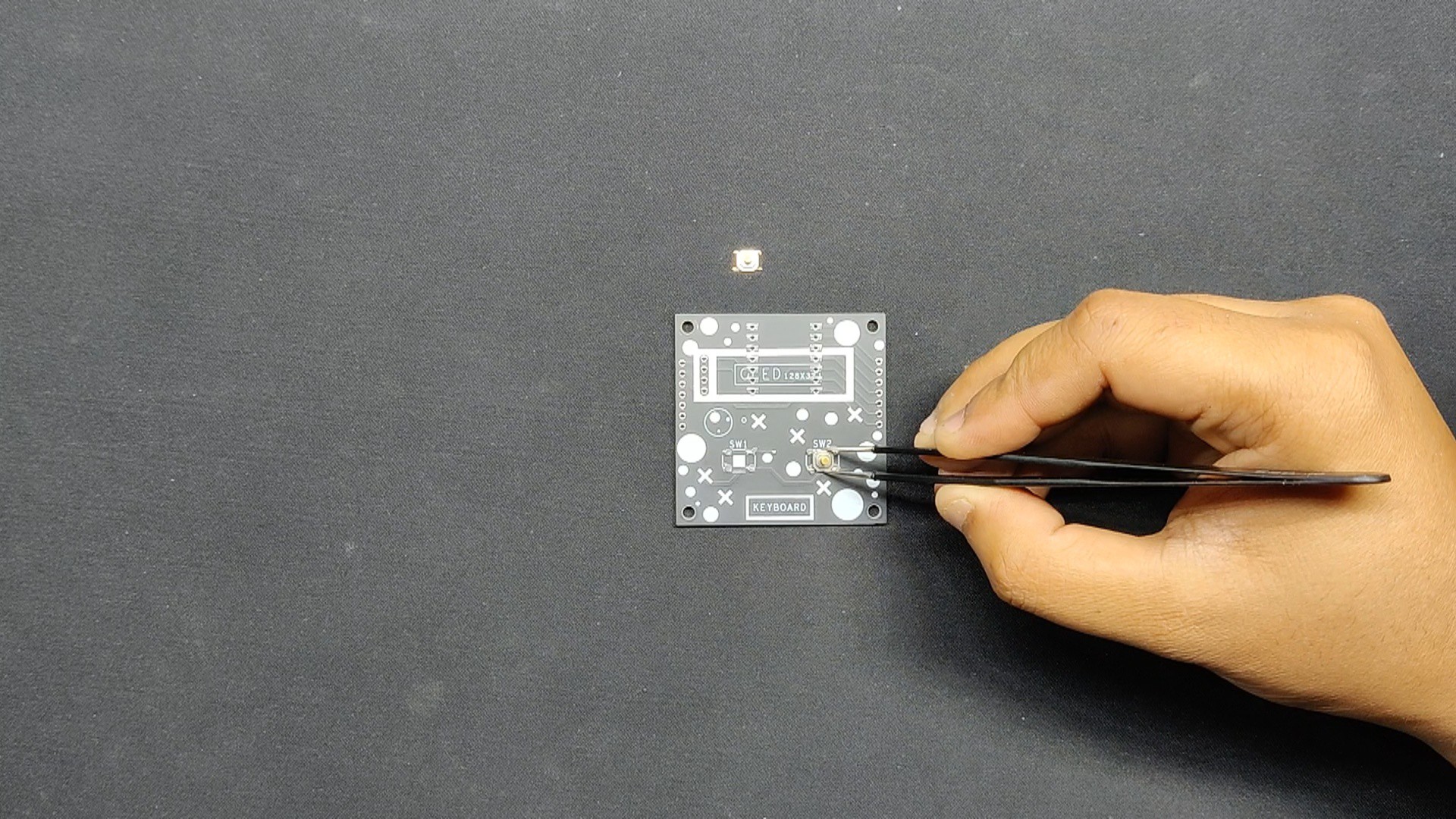
Next, we pick and place the SMD Switch in its location using an ESD Tweezer.
Subsequently, we remove the board and set it on our Reflow Hotplate, which raises the PCB's temperature from below to the point at which the solder paste melts and the SMD components are all connected to their pads.
We attached the pads of the two CON7 Female Header Pin connectors that we inserted from the back side of the PCB to the location of the XIAO Microcontroller.
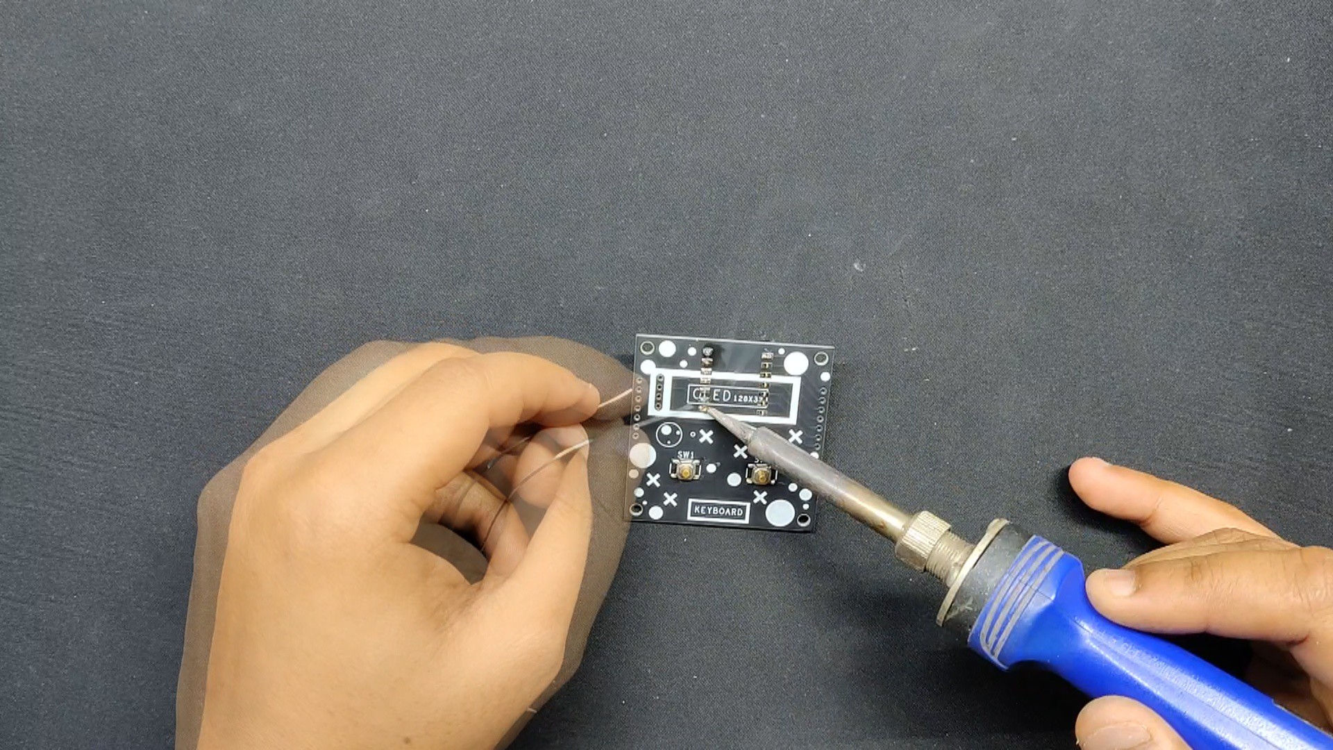
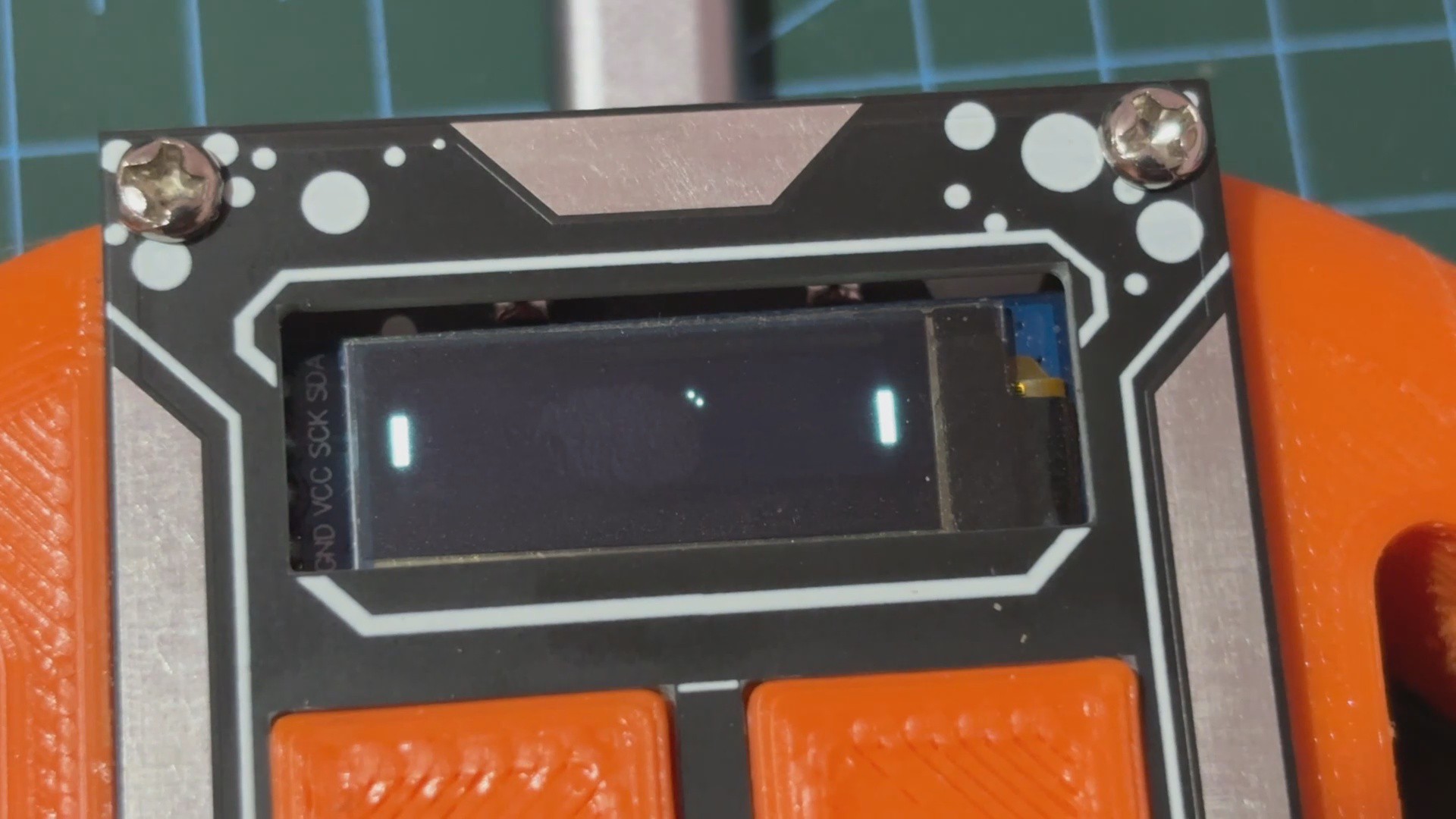
We soldered the OLED into place after adding it from the top side.
Board assembly is now complete.
2
Console Assembly
Connecting the 9mm PCB standoffs to the top layer of the board via its four mounting holes is how we begin the layer assembly procedure.
The top layer board was flipped, and the two 3D-printed switches were inserted into their designated slots.
Next, the midlayer was positioned from the bottom of the top layer.
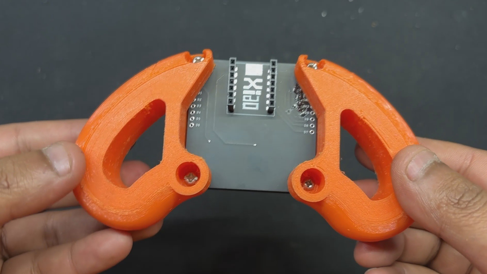
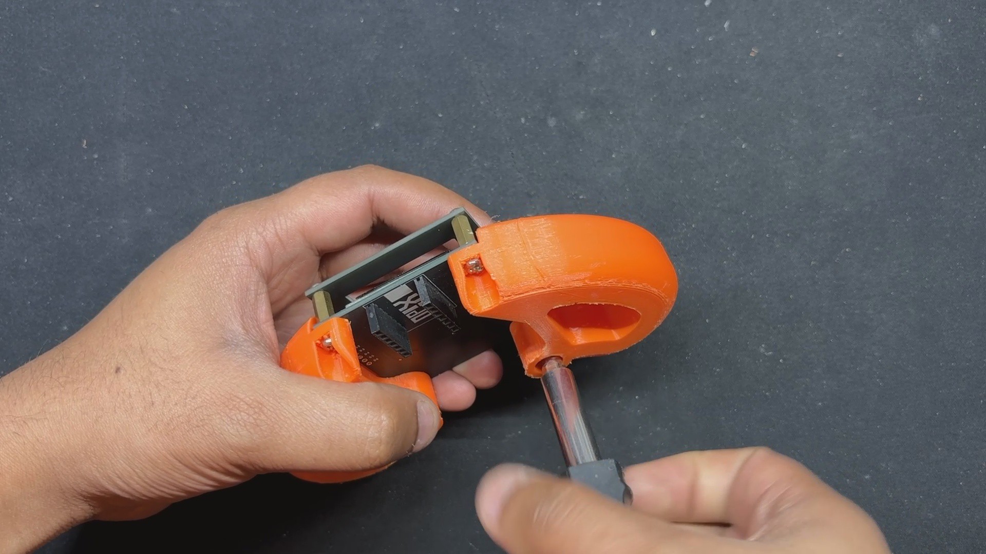
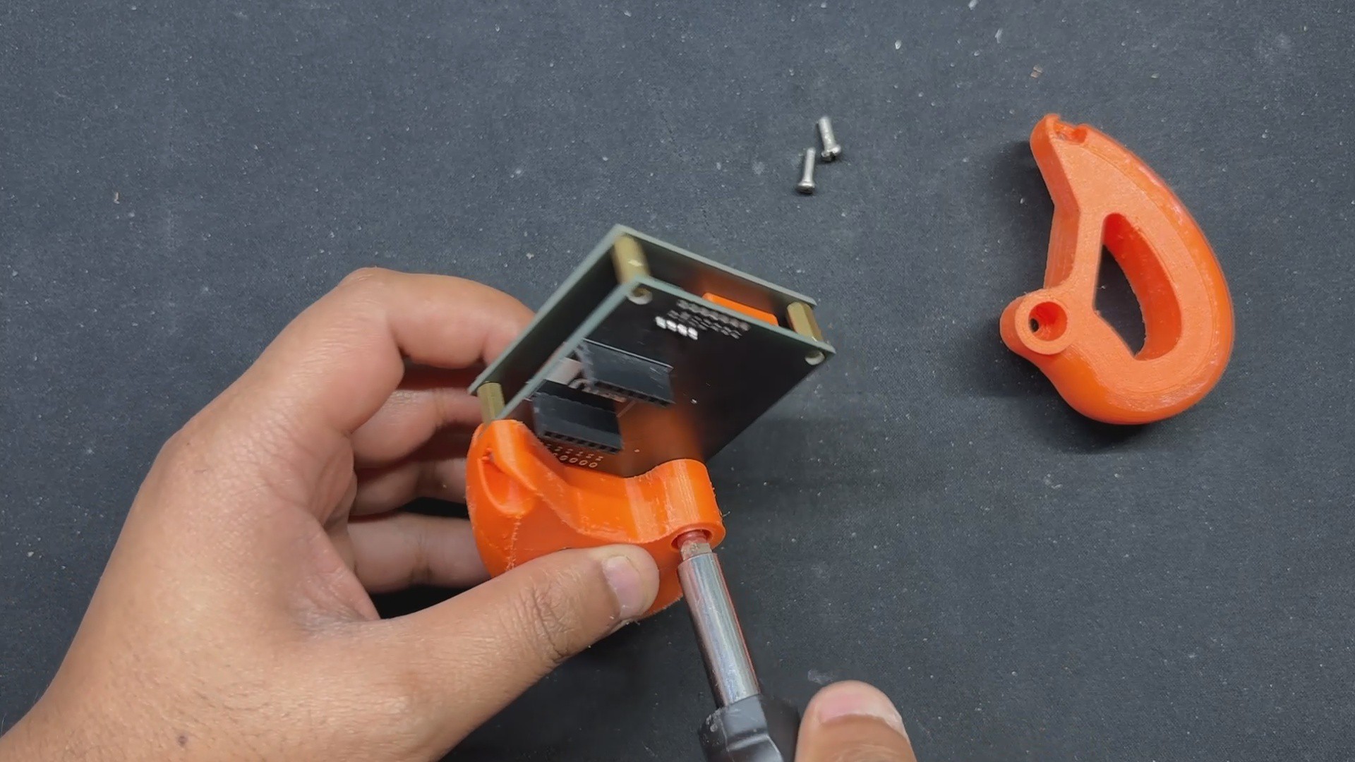
We then placed 3D-printed left and right handgrips over the midlayer and secured them with two M2.5 screws to the PCB standoffs.
After attaching both handhrips to the standoffs that connect the top and middle layers of the PCB, we installed the XIAO ESP32 and completed our console assembly.
3
CODE
Let's have a look at the code we built, and its a simple one.
we are using two buttons to control the paddle. It includes initialization for the display and buttons, variables to track the paddle and ball positions, and game logic to handle ball movement, paddle control, and collision detection.
The game starts with a "PONG PRO" welcome screen and shows "You Win!" or "You Lose!" messages when the game ends, depending on whether the player or the computer missed the ball. The game then resets for another round, continuing in a loop until the device is turned off.
4
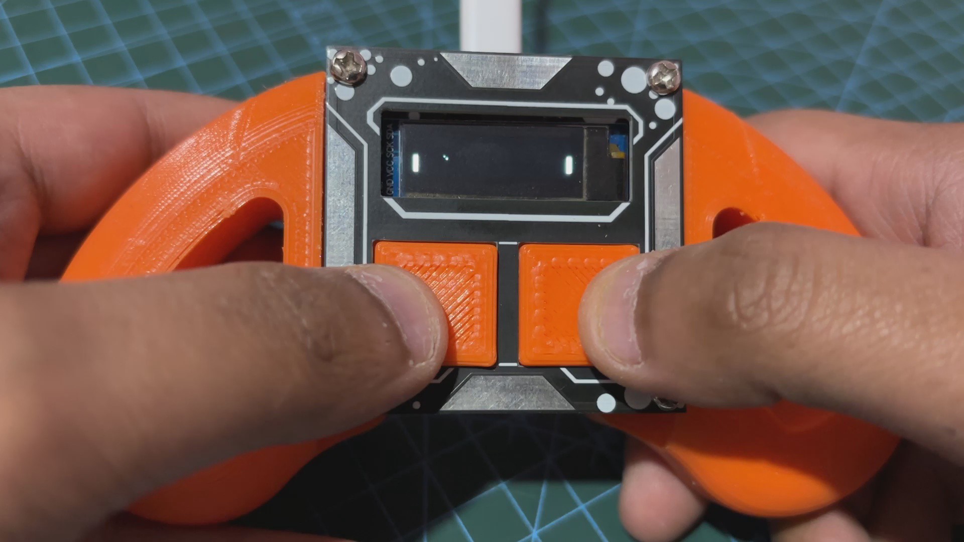
RESULT
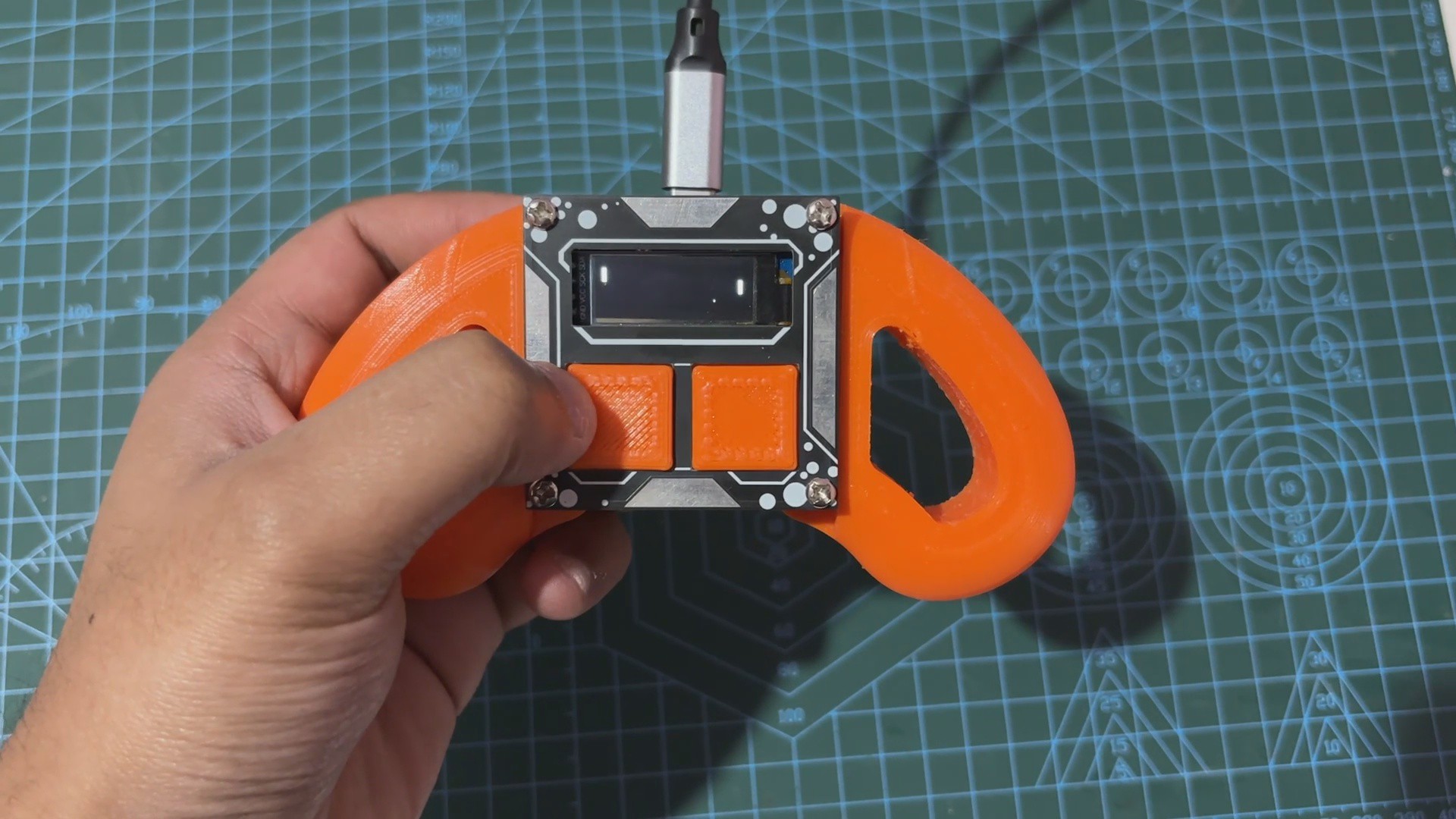
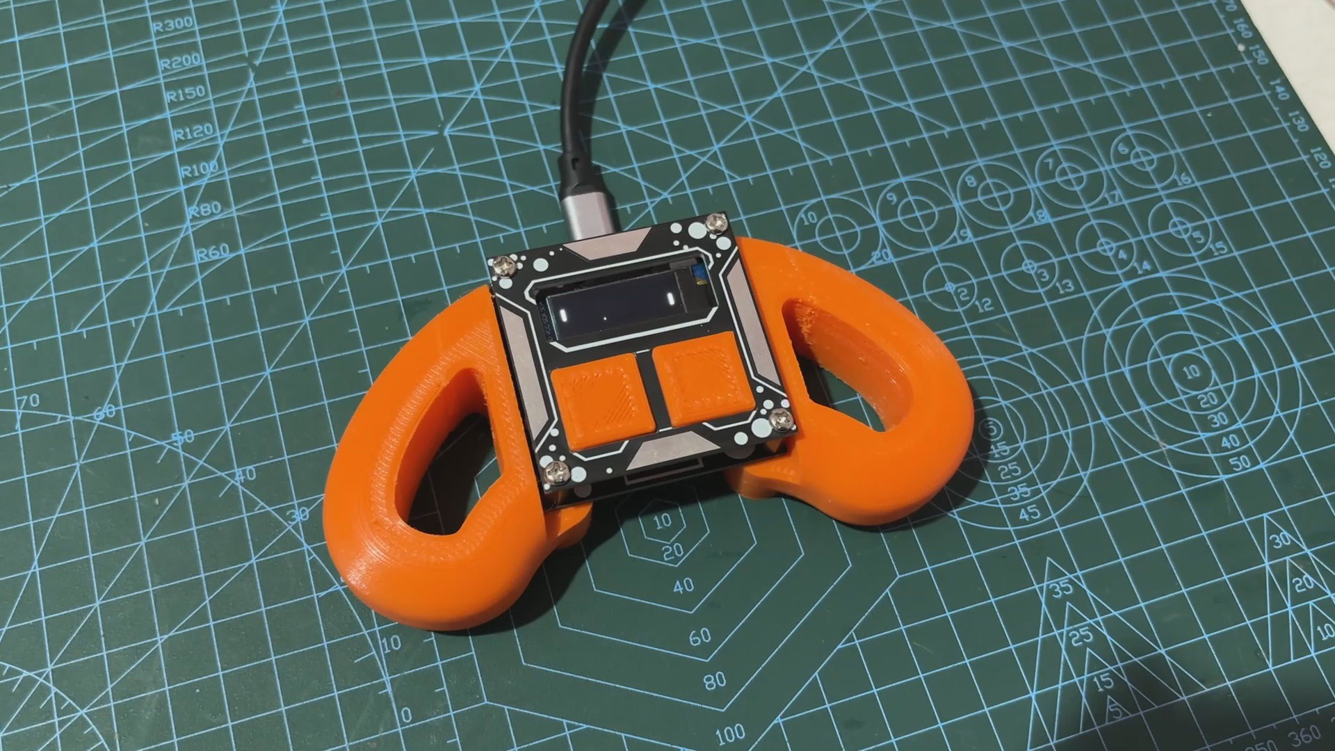
Here's the end result of this simple yet fun build: a super small handheld game device that runs PONG. In this game, our opponent is the computer, and we are playing against it. When the computer misses the ball, a splash screen appears, indicating that we have won; if we miss the ball, a splash screen appears, indicating that we have lost.
Overall, this is a fun little project that is almost finished; however, because this device is powered via USB port, we haven't included a battery, which we will address in the next iteration of this project.
Special thanks to HQ NextPCB for providing components that I've used in this project; check them out for getting all sorts of PCB or PCBA-related services for less cost.
Thanks for reaching this far, and I will be back with a new project soon.
 Arnov Sharma
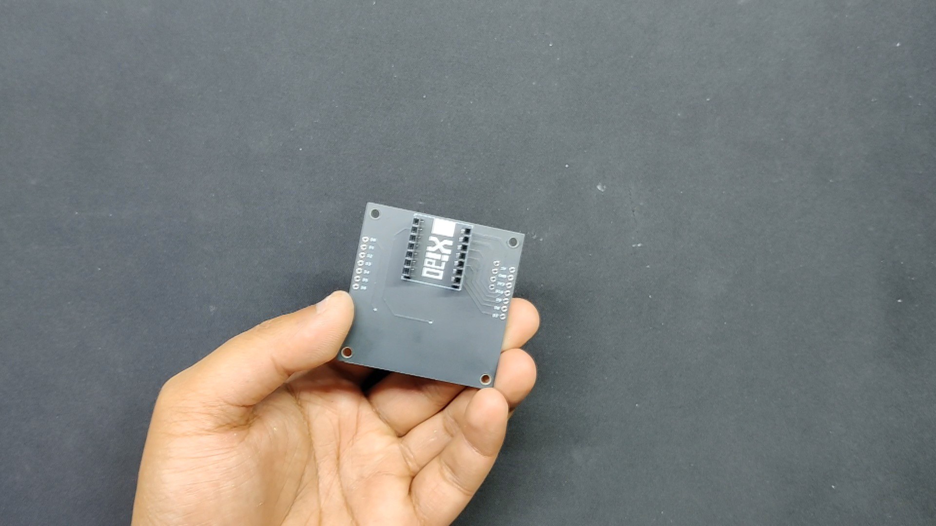

Discussions
Become a Hackaday.io Member
Create an account to leave a comment. Already have an account? Log In.