Arnov Sharma
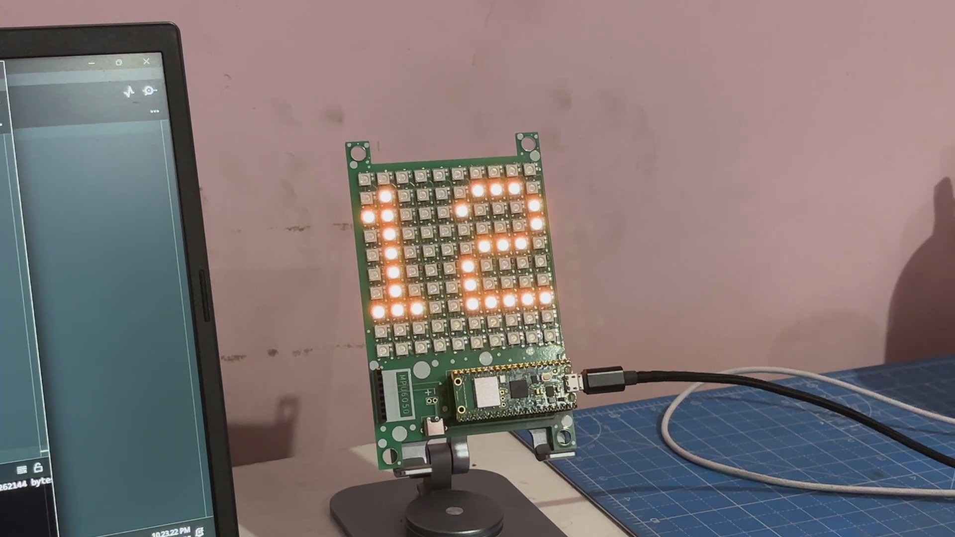
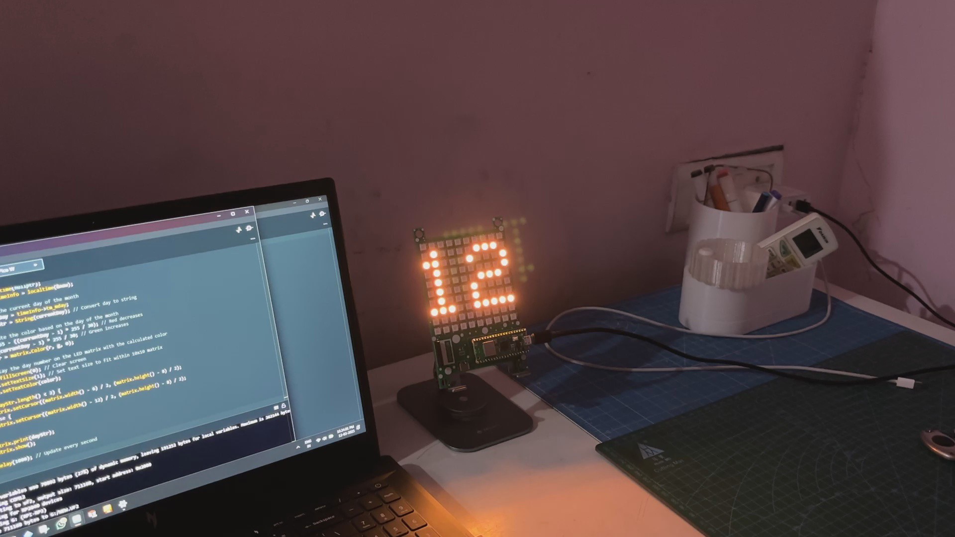
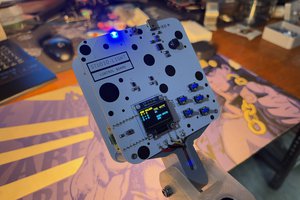
This date counter, similar to a clock, displays the current day of the month. It's a fun and eye-catching device to keep track of the date, with the extra bonus of the color changing from red to green as the days pass. It isn't as precise as a clock with hours, minutes, and seconds, but it does provide a clear daily indication of where you are in the month.
Our goal for this project was to develop a basic desk date clock that tells us what day it is; it begins with RED and turns to green as the day progresses, signaling the end of the month.
This project is basically version 1 of a future Matrix Clock project, which i will be preparing in the upcoming months.
Matrix Design
For this project, we are utilizing one of our previous matrix projects, which was a matrix with a dedicated microcontroller board (Raspberry Pi PICO) that could be utilized for future RGB matrix-based projects that include our date counter.
https://www.instructables.com/Raspberry-Pi-Pico-Matrix-Project/
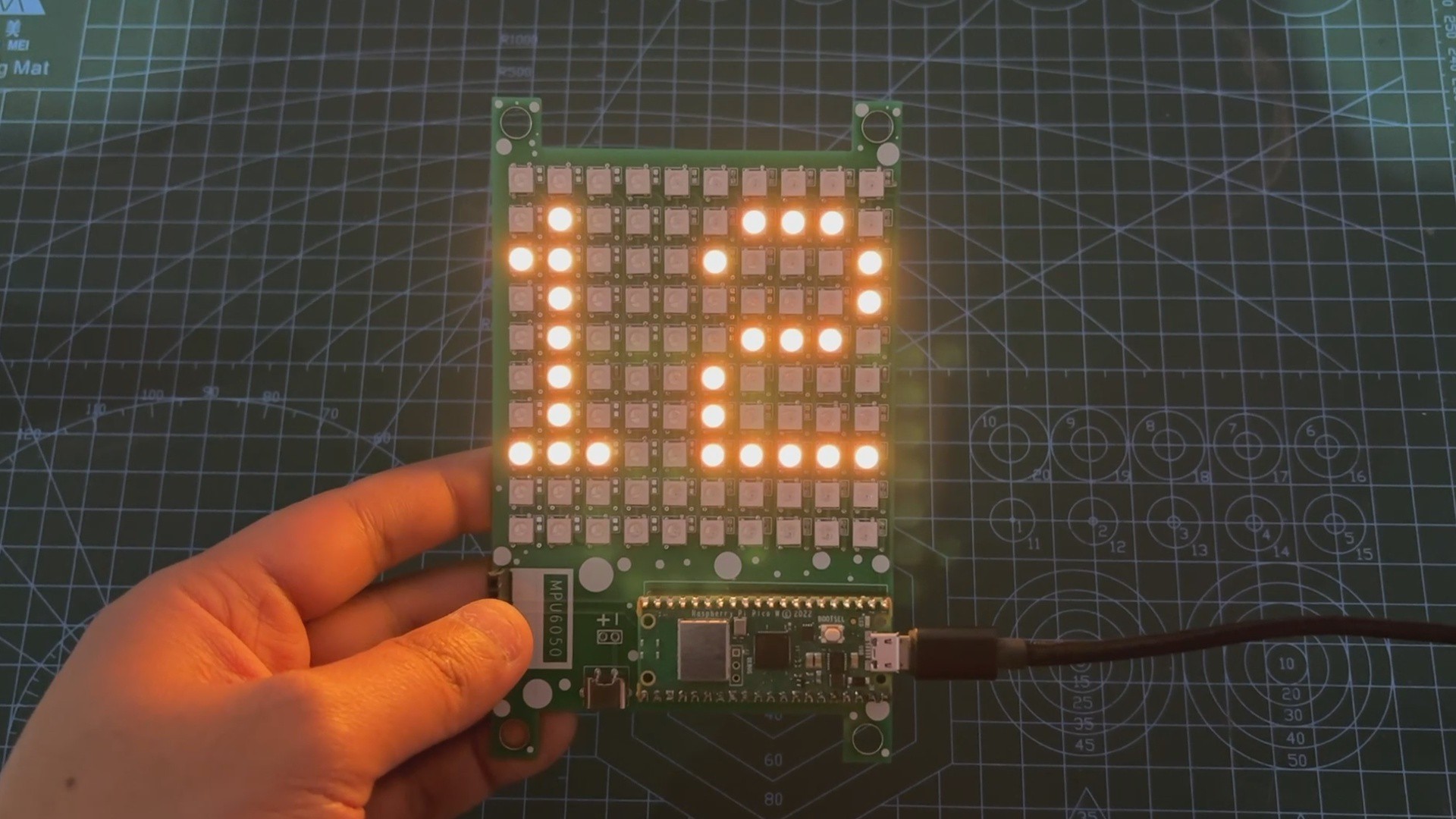
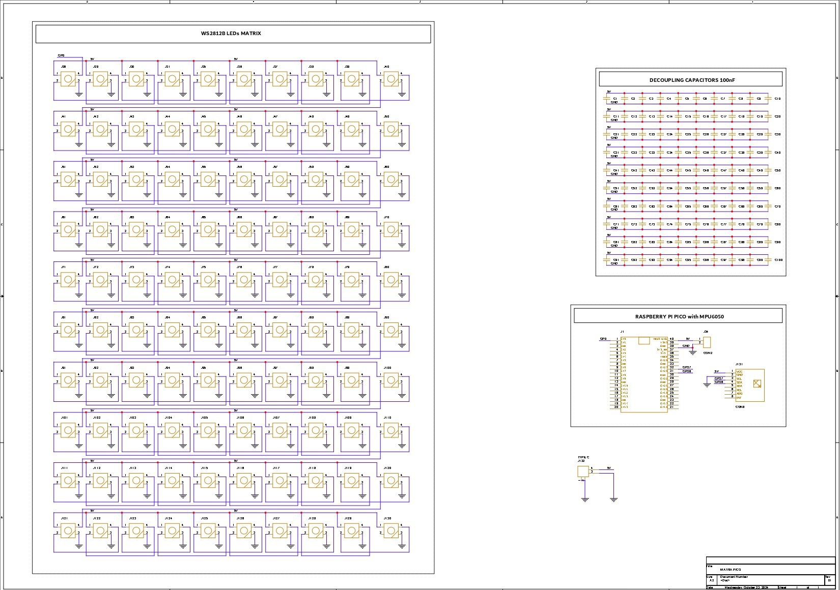
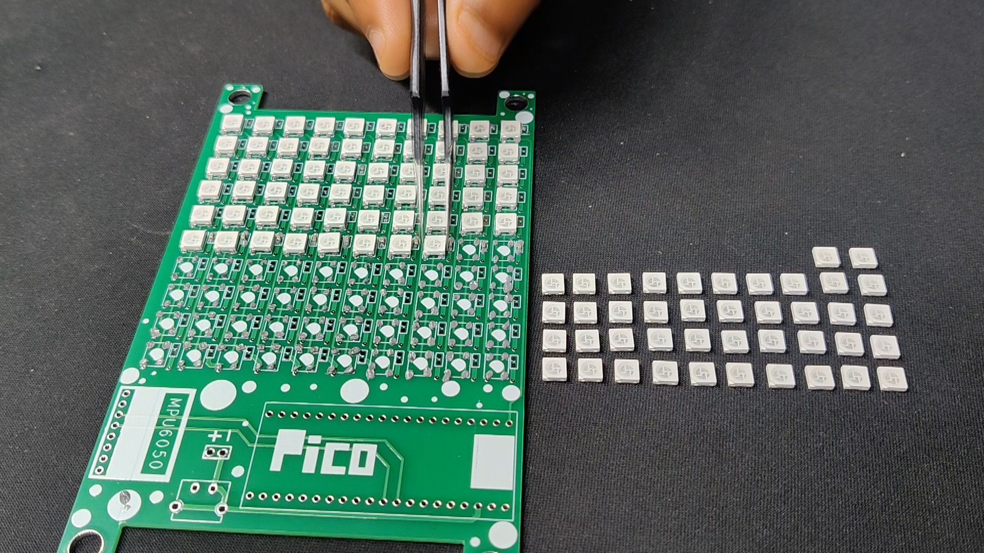
The two main components of this project's circuit are the LED matrix itself, which is made up of 100 WS2812B LEDs connected in their standard format, connecting the first LED's dout to the second's din, the second LED's dout to the second's din, and so on until the hundredth LED. The VCC and GND of each LED are connected in parallel.
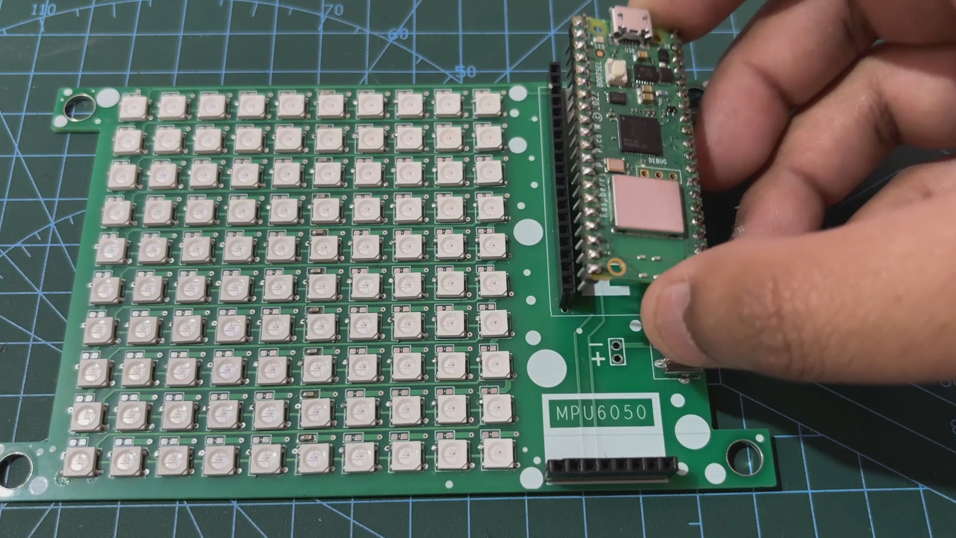
The second component of the circuit is a Raspberry Pi Pico W. The first LED Din is attached to the Raspberry Pi Pico's GPIO D0. We put a USB Type-C port alongside Pico's 5V IN and GND connectors to power the board using a type-C connector.
We put 100 decoupling capacitors to each WS2812B LED, but in the end, we only used 10x 100 nF capacitors, one for each row.
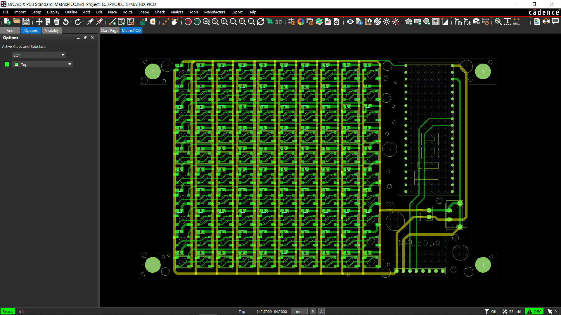
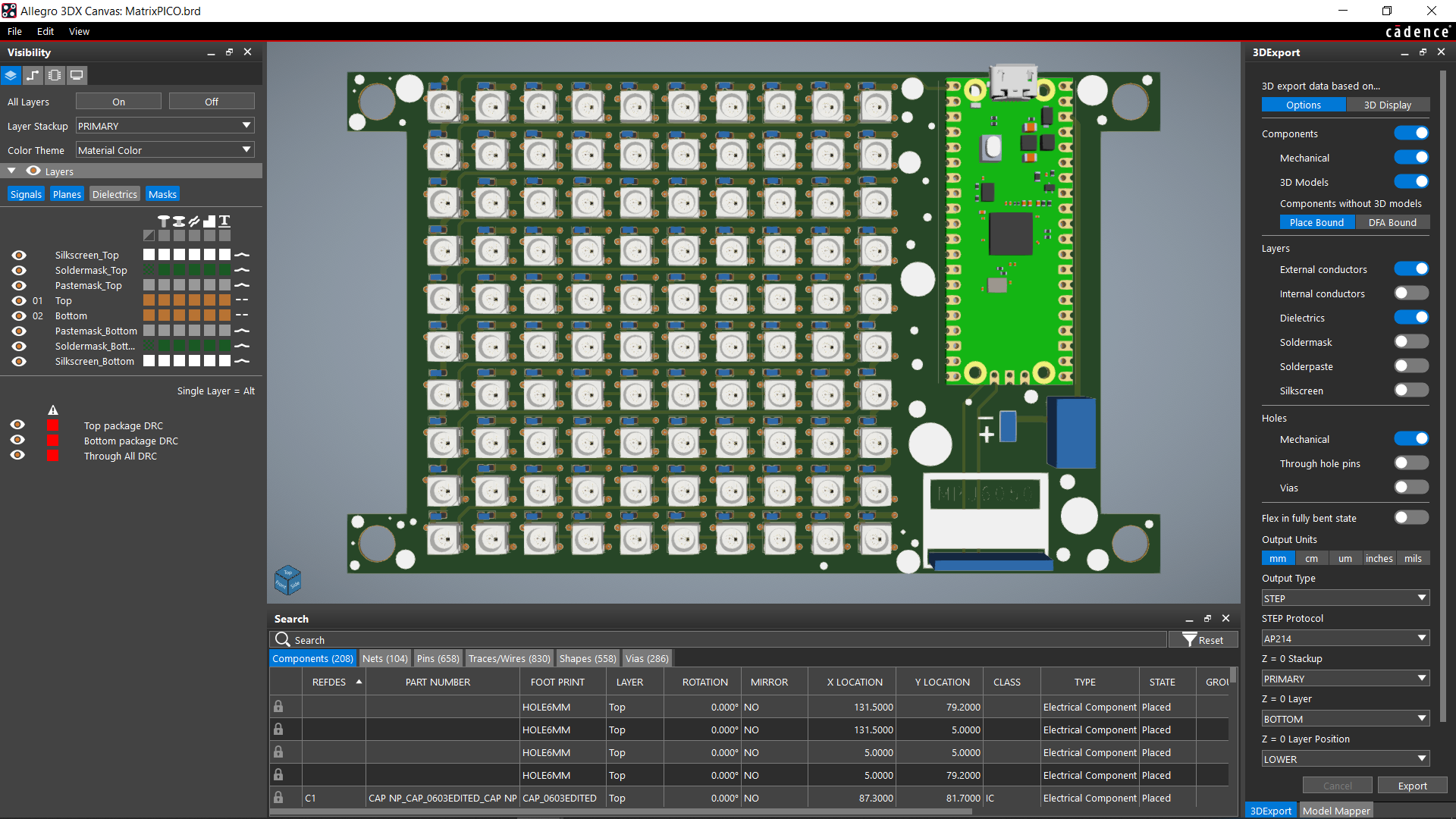
Once the design was finished, we saved it as a board file and put all 100 LEDs in a 10x10 row and column grid.
Please take note that the LEDs D1 through D10 are placed in a single row. D11 appears at the start of the new column and extends to D20, followed by D21, which appears at the start of the next column and extends to D100. This is also known as the serpentine matrix or snake matrix pattern.
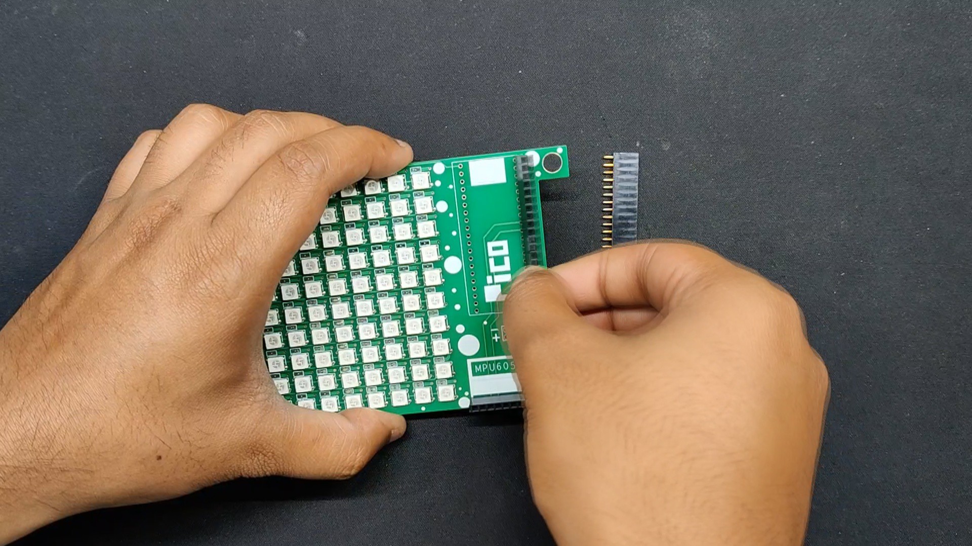
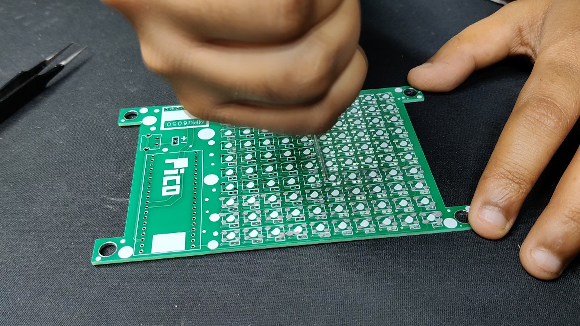
After setting up the PCB and installing the Pico and all SMD components, we exported the Gerber data, which will be sent to a PCB manufacturer for samples.
HQ NextPCB Service
After completing the PCB design, we export the Gerber data and send it to HQ NextPCB for samples.
For the mid and top layer boards, two orders were placed. We ordered a black Solder mask with white screen for the mid- and top-layer boards.
After placing the order, the PCBs were received within a week, and the PCB quality was pretty great.
In addition, I have to bring in HQDFM to you, which helped me a lot through many projects. Huaqiu’s in-house engineers developed the free Design for Manufacturing software, HQDFM, revolutionizing how PCB designers visualize and verify their designs.
Take advantage of NextPCB's Accelerator campaign and get 2 free assembled RP2040-based PCBs for your innovative projects.
https://www.nextpcb.com/blog/rp2040-free-pcba-prototypes-nextpcb-accelerator
This offer covers all costs, including logistics, making it easier and more affordable to bring your ideas to life. SMT services can be expensive, but NextPCB is here to help you overcome that hurdle. Simply share your relevant project, and they'll take care of the rest. Don't miss out on this amazing opportunity to advance your tech creations!
HQDFM: Free Online Gerber Viewer and DFM Analysis Tool
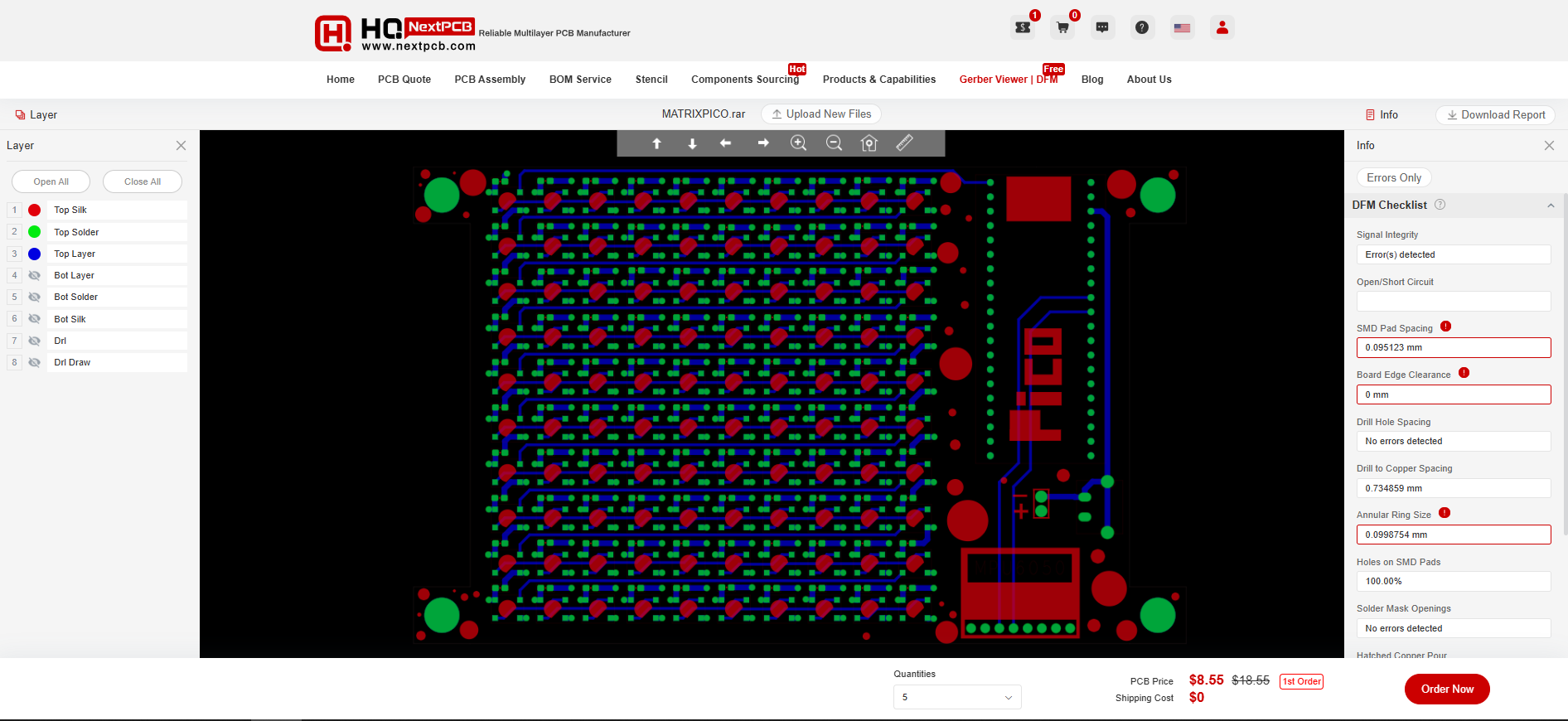
Also, NextPCB has its own Gerber Viewer and DFM analysis software.
Your designs are improved by their HQDFM software (DFM) services. Since I find it annoying to have to wait around for DFM reports from manufacturers, HQDFM is the most efficient method for performing a pre-event self-check.
Here is what online Gerber Viewer shows me. Would not be more clear. However, for full function, like DFM analysis for PCBA, you need to download the software. The online version only provides a simple PCB DFM report.
With...
Read more »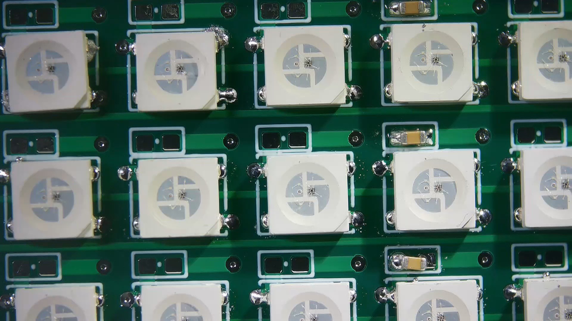


 Kyle
Kyle