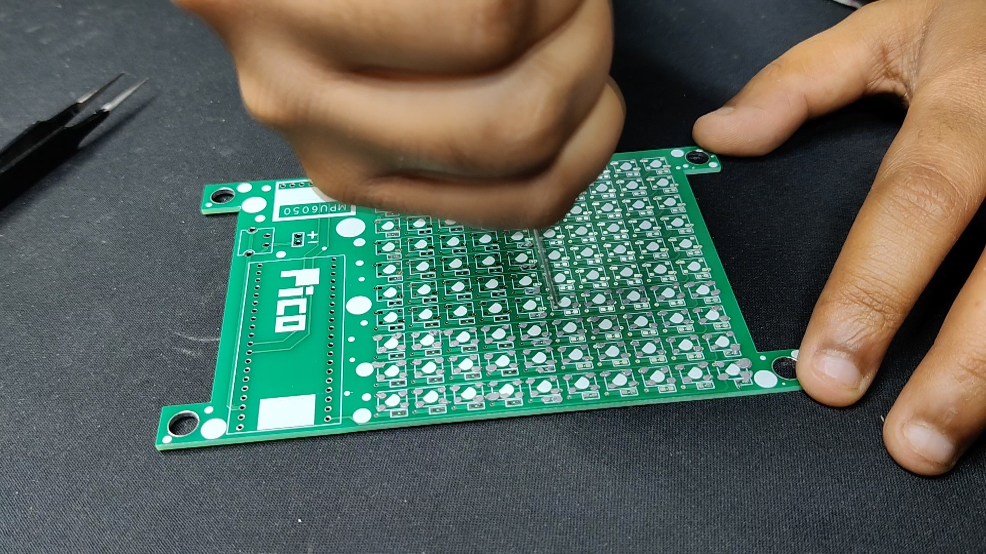
Using a solder paste dispenser needle, we apply solder paste to each component pad to begin the circuit assembly process. In this case, we are using 63/37 SnPB Solderpaste.
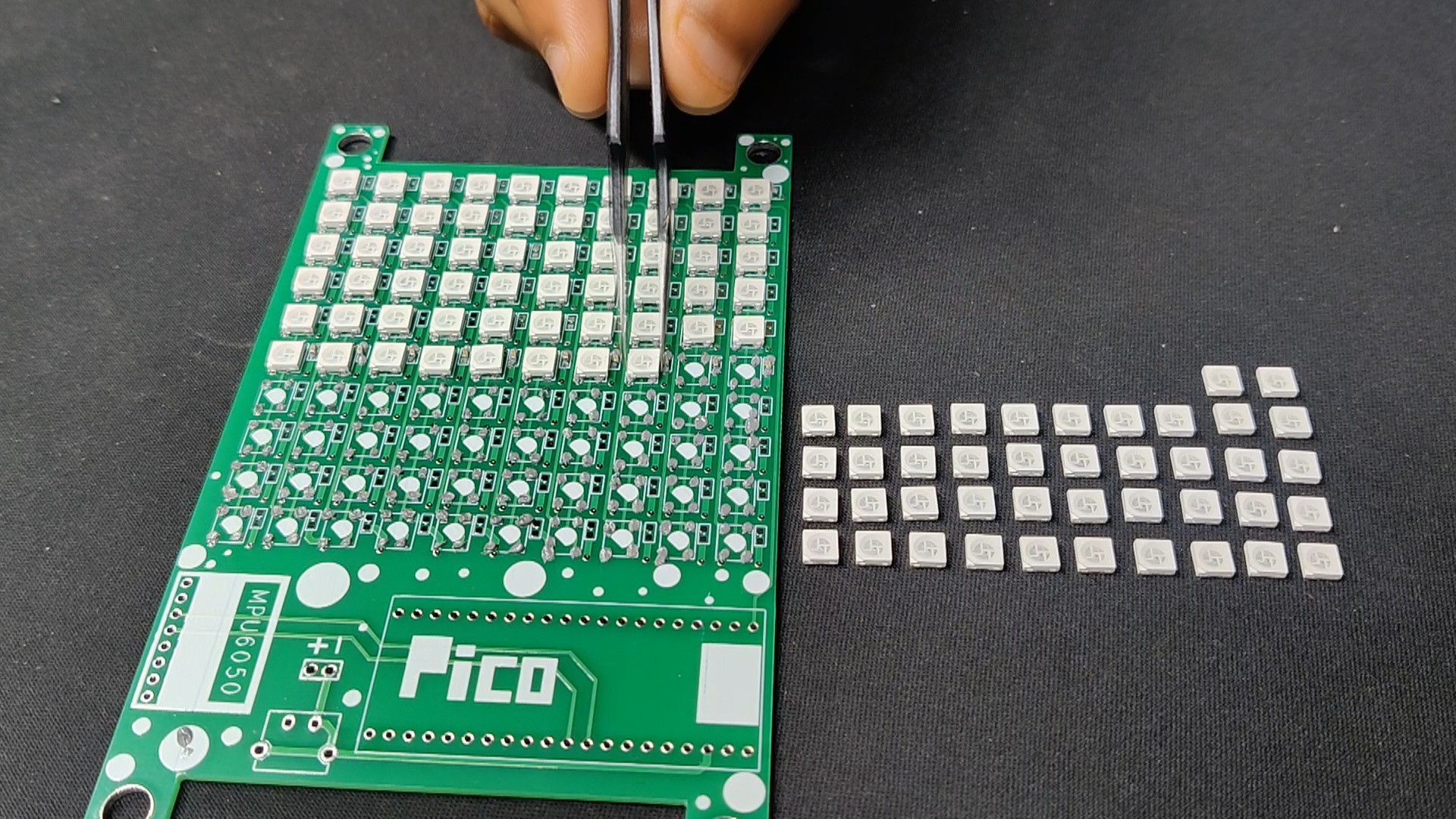
After that, we pick each WS2812B LED and place it into their correct position.
The PCB is then heated from below to the solder paste melting temperature by placing the circuit on the Reflow Hotplate, which causes all of the SMD LEDs to be connected to their pads.
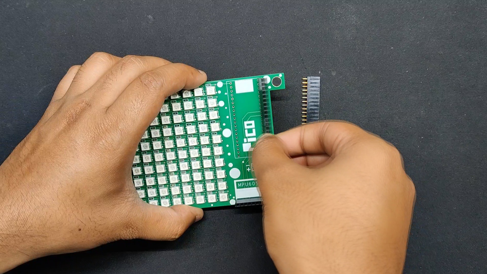
After reflow, we place the THT components, which consist of a female header pin connector for the Raspberry Pi Pico W and a USB-type C port.
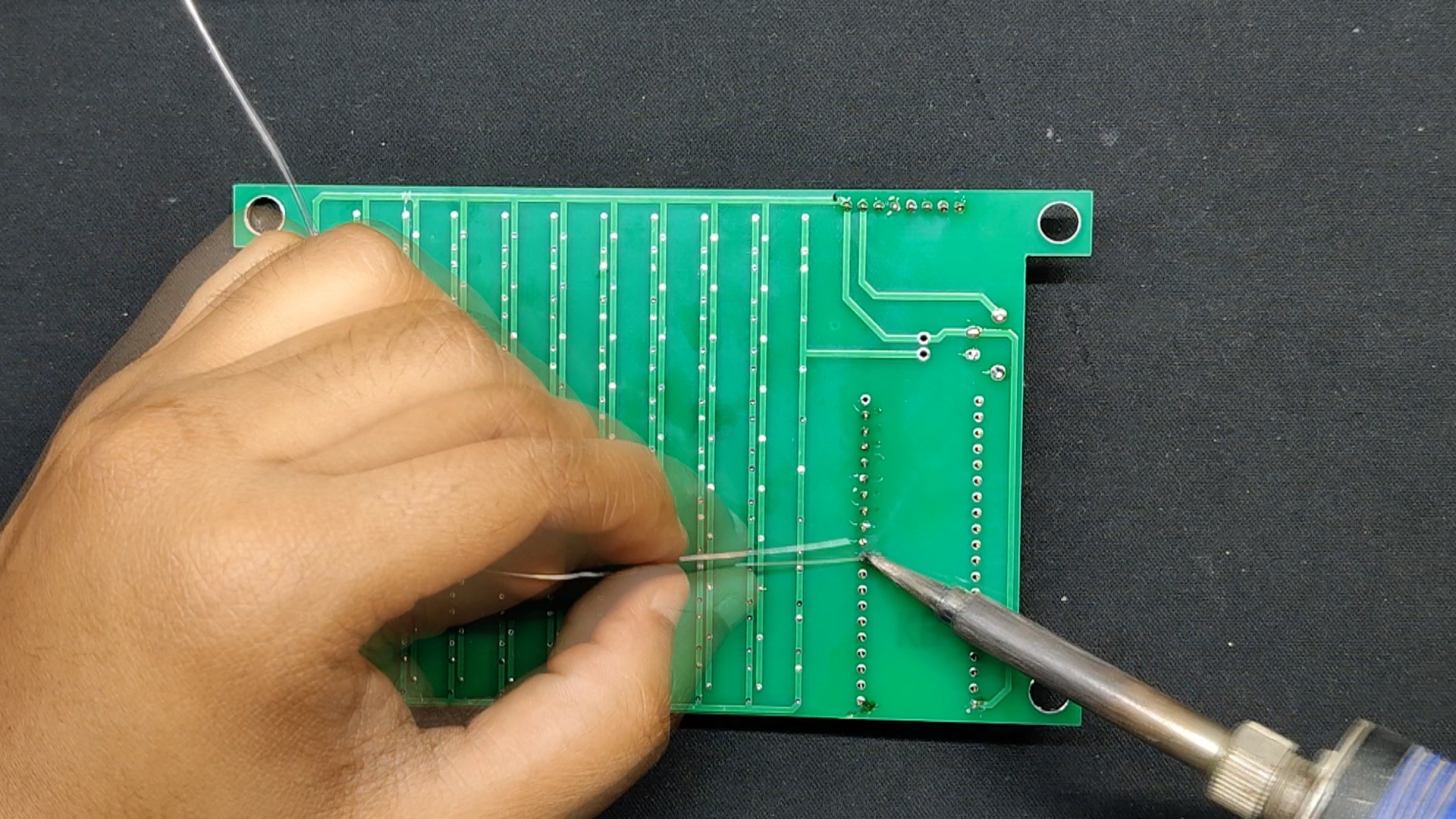
Using a soldering iron, we solder the leads of every through-hole component from the bottom side of the board.
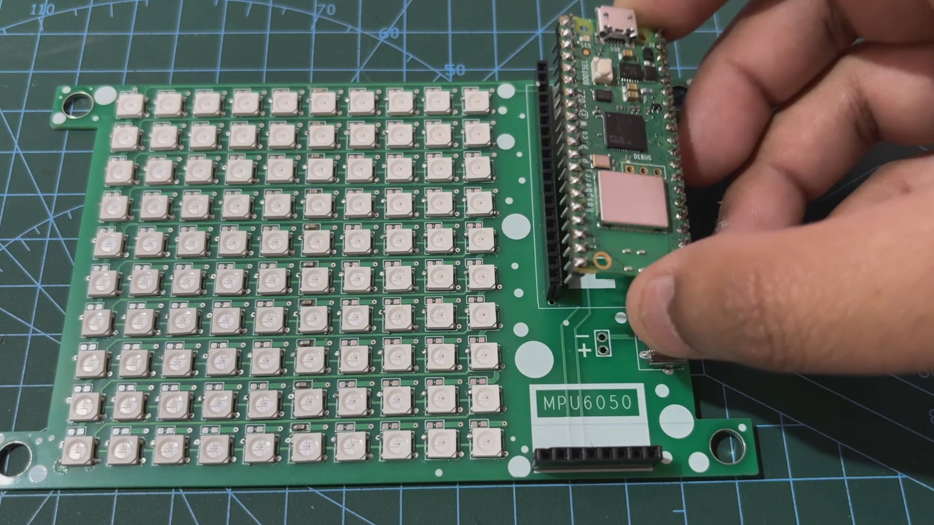
At last, we installed the Raspberry Pi PICO W on the header pins and our PCB assembly process is complete.
2
DEMO TEST CODE
For the Demo test sketch for this project, we created a number counter sketch that counts from 1 to 30 with a one-second interval. We added a feature to this test code that causes a color shift from red to green.
#include<Adafruit_NeoPixel.h>#include<Adafruit_GFX.h>#include<Adafruit_NeoMatrix.h>#define MATRIX_PIN 12 // GPIO pin connected to the LED matrix data pin#define MATRIX_WIDTH 10#define MATRIX_HEIGHT 10
Adafruit_NeoMatrix matrix = Adafruit_NeoMatrix(MATRIX_WIDTH, MATRIX_HEIGHT, MATRIX_PIN,
NEO_MATRIX_TOP + NEO_MATRIX_LEFT +
NEO_MATRIX_ROWS,
NEO_GRB + NEO_KHZ800);
voidsetup(){
Serial.begin(115200);
Serial.println("Starting color fade test...");
// Initialize matrix
matrix.begin();
matrix.setTextWrap(false);
matrix.setBrightness(50);
matrix.setRotation(3); // Rotate the text 90 degrees in the opposite direction
}
voidloop(){
for (int i = 1; i <= 30; i++) {
// Calculate the color based on the day of the monthint r = 255 - ((i - 1) * 255 / 30); // Red decreasesint g = (i - 1) * 255 / 30; // Green increasesint color = matrix.Color(r, g, 0);
// Display the day number on the LED matrix with the calculated color
matrix.fillScreen(0); // Clear screen
matrix.setTextSize(1); // Set text size to fit within 10x10 matrix
matrix.setTextColor(color);
String dayStr = String(i); // Convert day to stringif (dayStr.length() < 2) {
matrix.setCursor((matrix.width() - 6) / 2, (matrix.height() - 8) / 2);
} else {
matrix.setCursor((matrix.width() - 12) / 2, (matrix.height() - 8) / 2);
}
matrix.print(dayStr);
matrix.show();
Serial.print("Displaying day: "); Serial.print(dayStr); Serial.print(" with color: ");
Serial.print("R="); Serial.print(r); Serial.print(", G="); Serial.println(g);
delay(1000); // Update every second
}
}
Here, we begin the month with a red color and as the days pass and we approach 30, the color changes from red to green.
Make sure you install the required libraries: Prior to using this sketch, install Adafruit NeoPixel, Adafruit GFX, and Adafruit NeoMatrix.
3
MAIN CODE
After testing the demo test code, let's have a look at the main code for this project and its a simple one.
#include<WiFi.h>#include<NTPClient.h>#include<WiFiUdp.h>#include<Adafruit_NeoPixel.h>#include<Adafruit_GFX.h>#include<Adafruit_NeoMatrix.h>#include<time.h>// WiFi credentialsconstchar* ssid = "UR SSID";
constchar* password = "UR PASS";
// Define NTP Client to get time
WiFiUDP ntpUDP;
NTPClient timeClient(ntpUDP, "pool.ntp.org", 19800, 60000); // IST is UTC+5:30 or 19800 seconds// Define LED matrix#define MATRIX_PIN 12 // GPIO pin connected to the LED matrix data pin#define MATRIX_WIDTH 10#define MATRIX_HEIGHT 10
Adafruit_NeoMatrix matrix = Adafruit_NeoMatrix(MATRIX_WIDTH, MATRIX_HEIGHT, MATRIX_PIN,
NEO_MATRIX_TOP + NEO_MATRIX_LEFT +
NEO_MATRIX_ROWS,
NEO_GRB + NEO_KHZ800);
voidsetup(){
Serial.begin(115200);
Serial.println("Setting up WiFi and NTP...");
// Initialize matrix
matrix.begin();
matrix.setTextWrap(false);
matrix.setBrightness(50);
matrix.setRotation(3); // Rotate the text 90 degrees in the opposite direction// Connect to WiFi
WiFi.begin(ssid, password);
while (WiFi.status() != WL_CONNECTED) {
delay(500);
Serial.print(".");
}
Serial.println("WiFi connected.");
// Initialize NTPClient
timeClient.begin();
}
voidloop(){
timeClient.update();
// Get current date and time from NTP clienttime_t rawTime = timeClient.getEpochTime();
structtm *timeInfo = localtime(&rawTime);// Extract the current day of the monthint currentDay = timeInfo->tm_mday;
String dayStr = String(currentDay); // Convert day to string// Calculate the color based on the day of the monthint r = 255 - ((currentDay - 1) * 255 / 30); // Red decreasesint g = (currentDay - 1) * 255 / 30; // Green increasesint color = matrix.Color(r, g, 0);
// Display the day number on the LED matrix with the calculated color
matrix.fillScreen(0); // Clear screen
matrix.setTextSize(1); // Set text size to fit within 10x10 matrix
matrix.setTextColor(color);
if (dayStr.length() < 2) {
matrix.setCursor((matrix.width() - 6) / 2, (matrix.height() - 8) / 2);
} else {
matrix.setCursor((matrix.width() - 12) / 2, (matrix.height() - 8) / 2);
}
matrix.print(dayStr);
matrix.show();
delay(1000); // Update every second
}
Our code is intended to display the current day of the month on an LED matrix, with a color transition from red to green as the days progress. The script begins by importing the following libraries: WiFi, NTPClient, and WiFiUdp for managing WiFi connections and retrieving time from the NTP server; and Adafruit_NeoPixel, Adafruit_GFX, and Adafruit_NeoMatrix for controlling the LED matrix.
An NTP client is instantiated to retrieve the current time from the "pool.ntp.org" NTP server, with an offset for Indian Standard Time (UTC+5:30).
The LED matrix is configured with a pin defined for GPIO 12, dimensions of 10x10, and specified connection and color order.
In the setup() function, serial communication is initiated for debugging purposes. The LED matrix is initialized with specified settings, including brightness and text rotation. The script then attempts to connect to the WiFi network using the provided credentials, waiting until the connection is established. Once connected, the NTP client is started to begin retrieving the current time.
In the loop() function, the NTP client is updated to retrieve the most recent time from the NTP server. The current date and time are retrieved and stored as a struct tm object. The current day of the month is then extracted and transformed into a string. The color used to represent the day is determined by the day of the month, transitioning from red on the first to green on the 30th or 31st. The LED matrix is then cleared, and the current day is printed in the calculated color, centering on the matrix. The display is refreshed every second to ensure that it is up to date.
4
RESULT
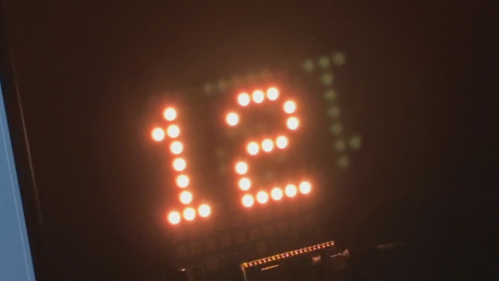
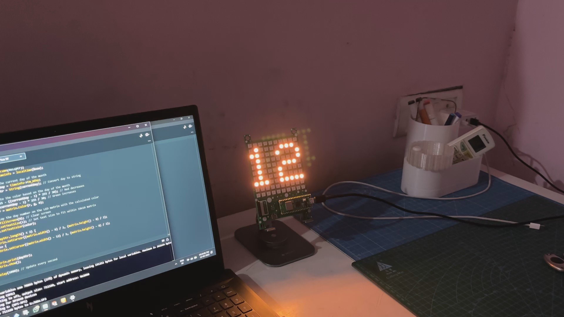
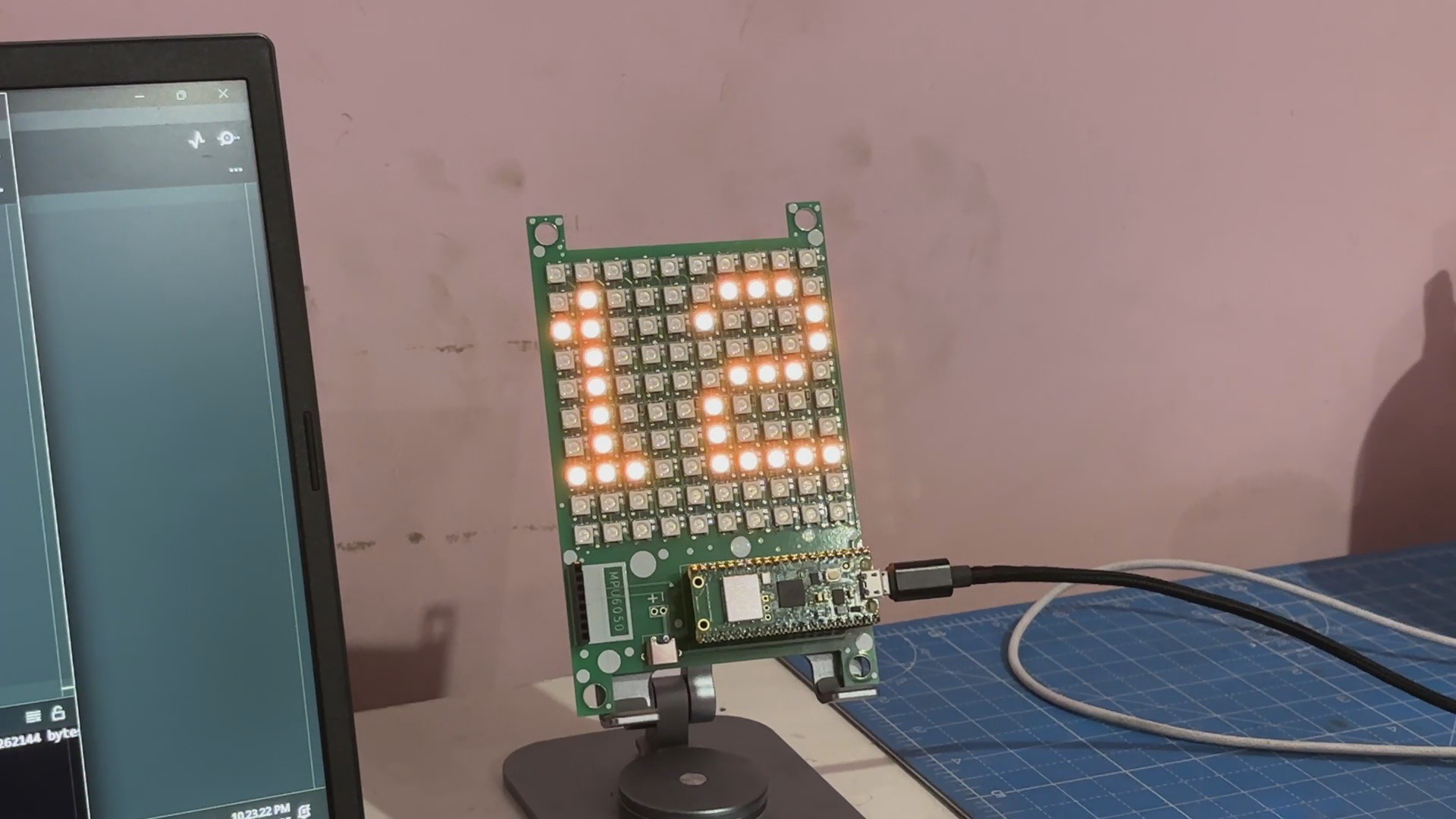
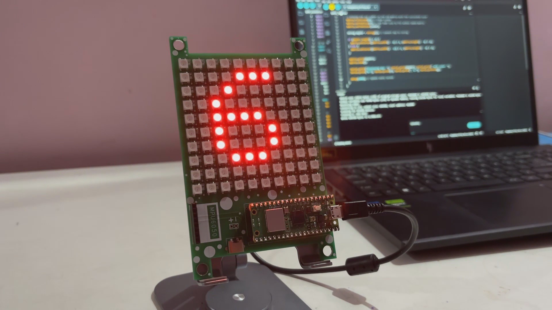
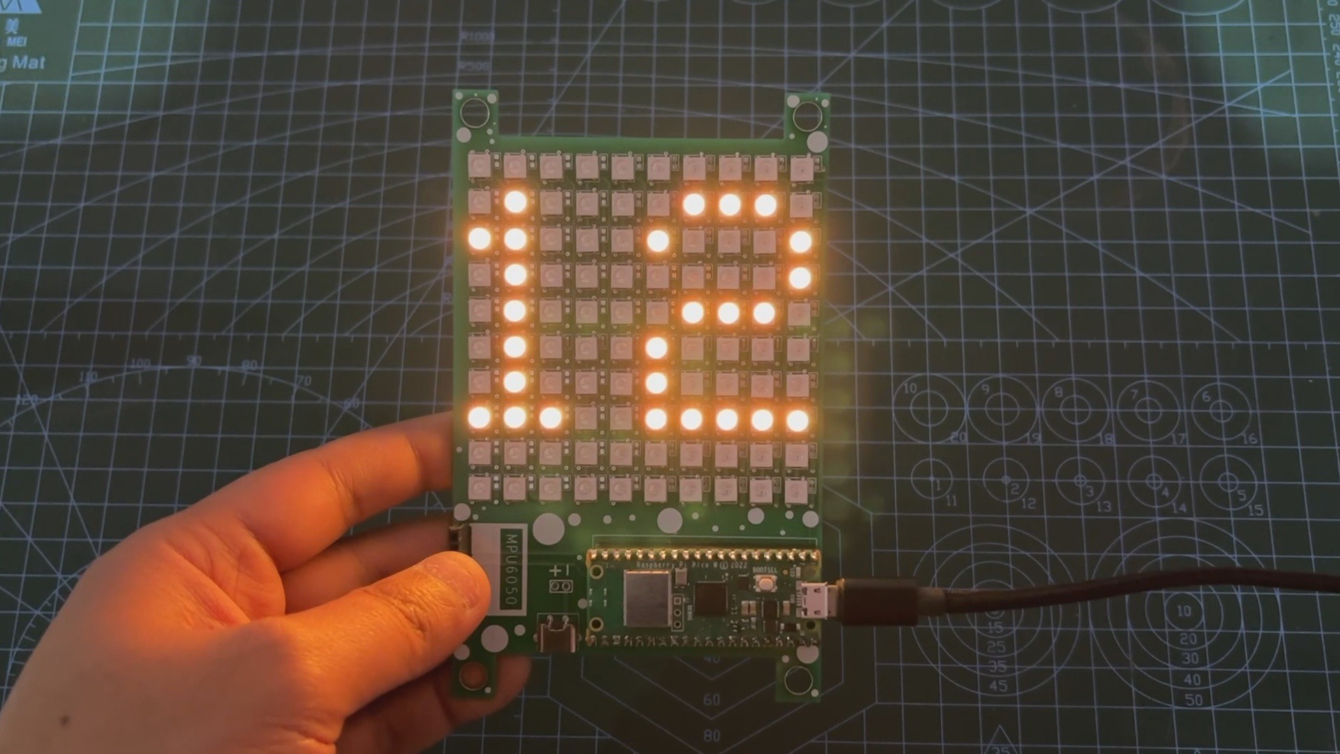
The end result of this simple yet practical build is a date counter that shows the current day of the month and has a color transition that changes from red to green as the day progresses.
This project creates a dynamic and visually appealing date counter by combining WiFi connectivity, NTP server time retrieval, and an LED matrix display.
I wish to improve the matrix size in the next edition. We are now utilizing a 10x10 matrix, which is fine if we only want to display a single number, but we want to display the entire date, including the month and year; therefore, we will need to increase the matrix significantly.
Also, we will be adding onboard power so the whole device can just work without using external power from the USB port.
This is it for today, folks. All the documents related to this project are attached, which you can checkout in this article. If you need any additional information, feel free to leave a comment, and I will be happy to assist you.
Special thanks to HQ NextPCB for providing components that I've used in this project; check them out for getting all sorts of PCB or PCBA-related services for less cost.
Thanks for reaching this far, and I will be back with a new project soon.
 Arnov Sharma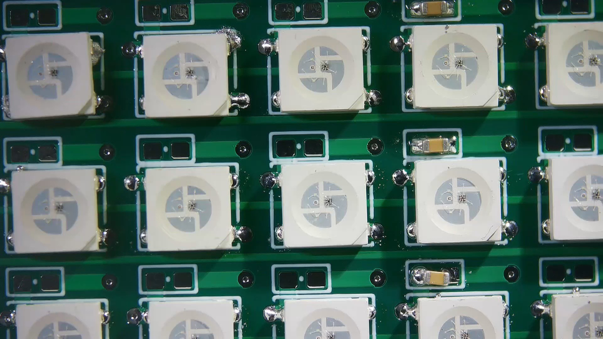



Discussions
Become a Hackaday.io Member
Create an account to leave a comment. Already have an account? Log In.