 Dami Kim
Feb 16 - 22
- With the help of our mentor (Kevin), was able to control the speed of the motor properly using a potentiometer
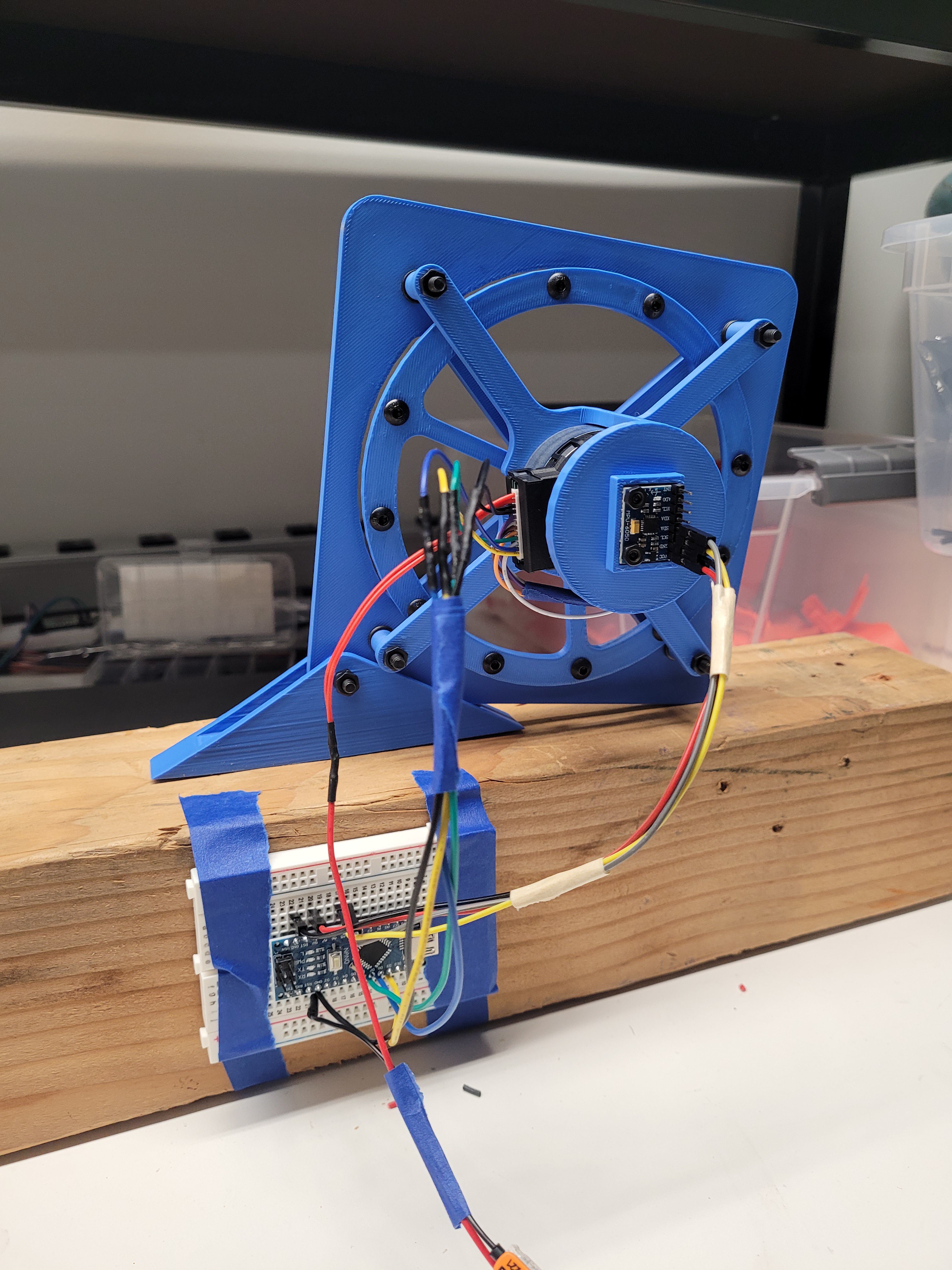
- Finished CAD design of the 6x6" 1 DoF platform that will test self balancing using one reaction wheel
- 3D printed the platform, assembled it, and secured to a heavy piece of wood block to keep it in place
- Switched from the BNO08x IMU to the MPU6050 because the BNO took up too much memory from the Arduino Nano
- Soldered wires for extension
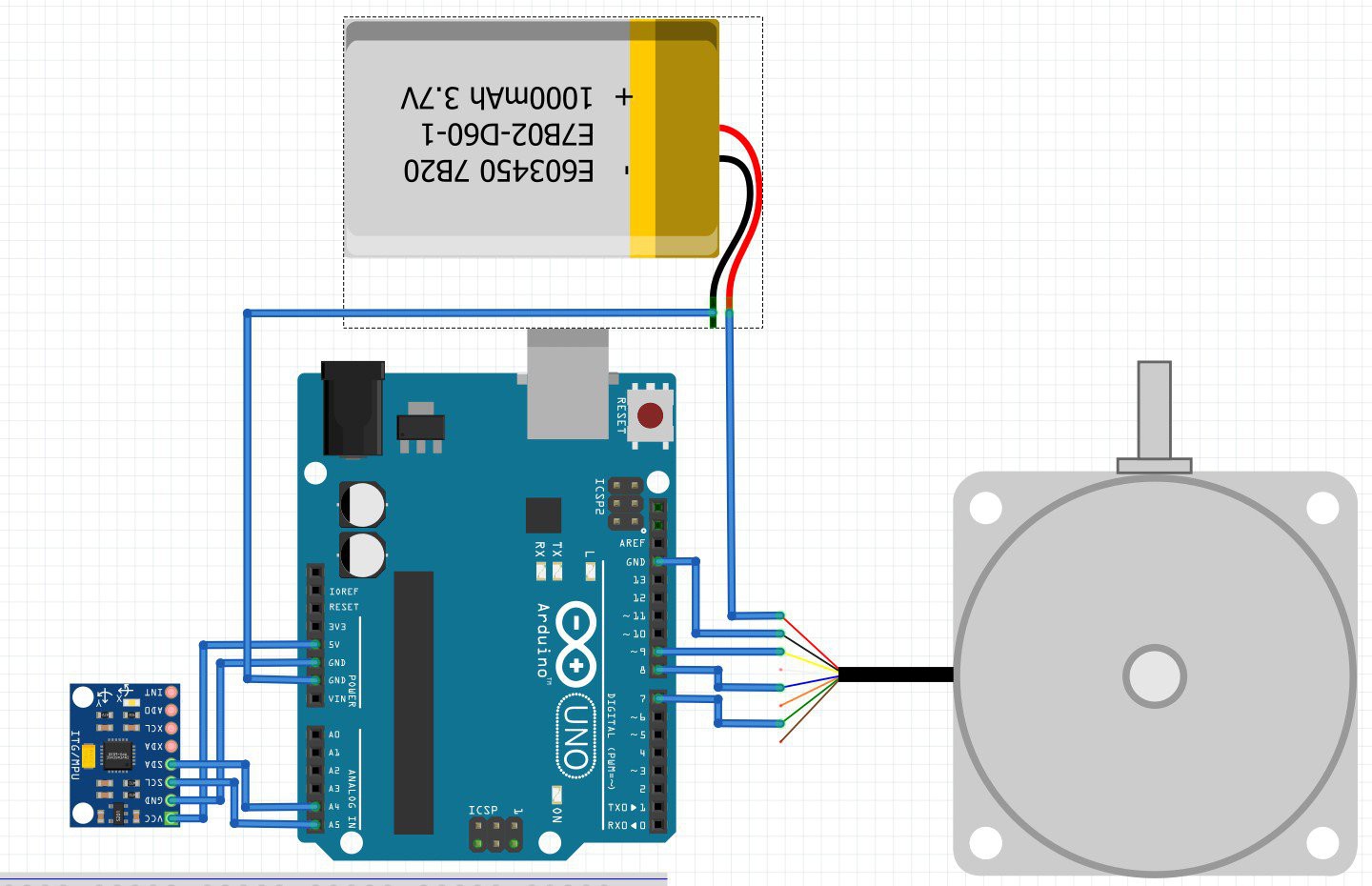
const int potentiometerPin = A0;  // Potentiometer connected to analog pin A0
#define PWM_PIN 9      // Yellow - Speed control (PWM)
#define START_PIN 8    // Blue - Start/Stop
#define DIR_PIN 7      // Green - Direction (CW/CCW)
#define BRAKE_PIN 4    // White - Brake (GND = brake, Floating = release)

void setup() {
    pinMode(START_PIN, OUTPUT);
    pinMode(DIR_PIN, OUTPUT);
    pinMode(BRAKE_PIN, OUTPUT);

    // Set default motor state
    digitalWrite(START_PIN, HIGH);  // Start motor
    digitalWrite(DIR_PIN, LOW);     // Default: CW rotation
    digitalWrite(BRAKE_PIN, HIGH);  // Release brake

    Serial.begin(9600);
    pinMode(9, OUTPUT);  // Set pin 9 as output for tone generation
}

void loop() {
  // Read the potentiometer value
  int potValue = analogRead(potentiometerPin);

  // Map the potentiometer value to the desired frequency range
  int frequency = map(potValue, 0, 1023, 1000, 26000);

  // Generate tone on pin 9
  tone(PWM_PIN, frequency);
  Serial.print(frequency);
  Serial.println(" Hz");
}
Discussions
Become a Hackaday.io Member
Create an account to leave a comment. Already have an account? Log In.