Close
0%
0%

Reaction Wheel Self Balancing Cube

This project attempts to prototype a self balancing cube using three reaction wheels

Similar projects worth following
Self balancing reaction wheel using Arduino, brushless DC motors, IMU, and Magnetic Encoder. A sufficiently sized/weighed reaction wheel can generate enough torque to tilt the platform upright.

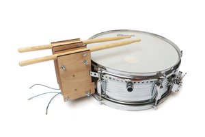
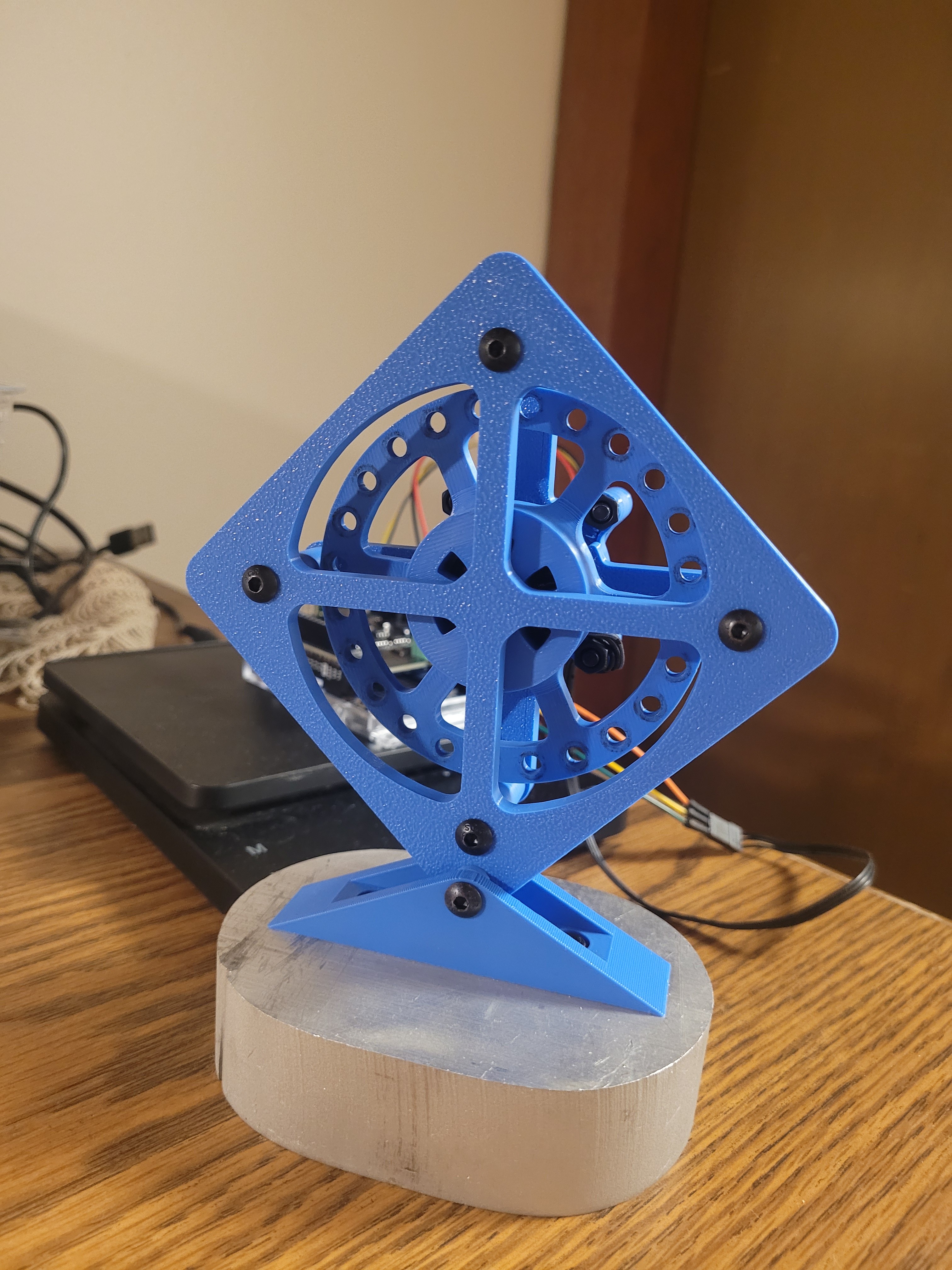
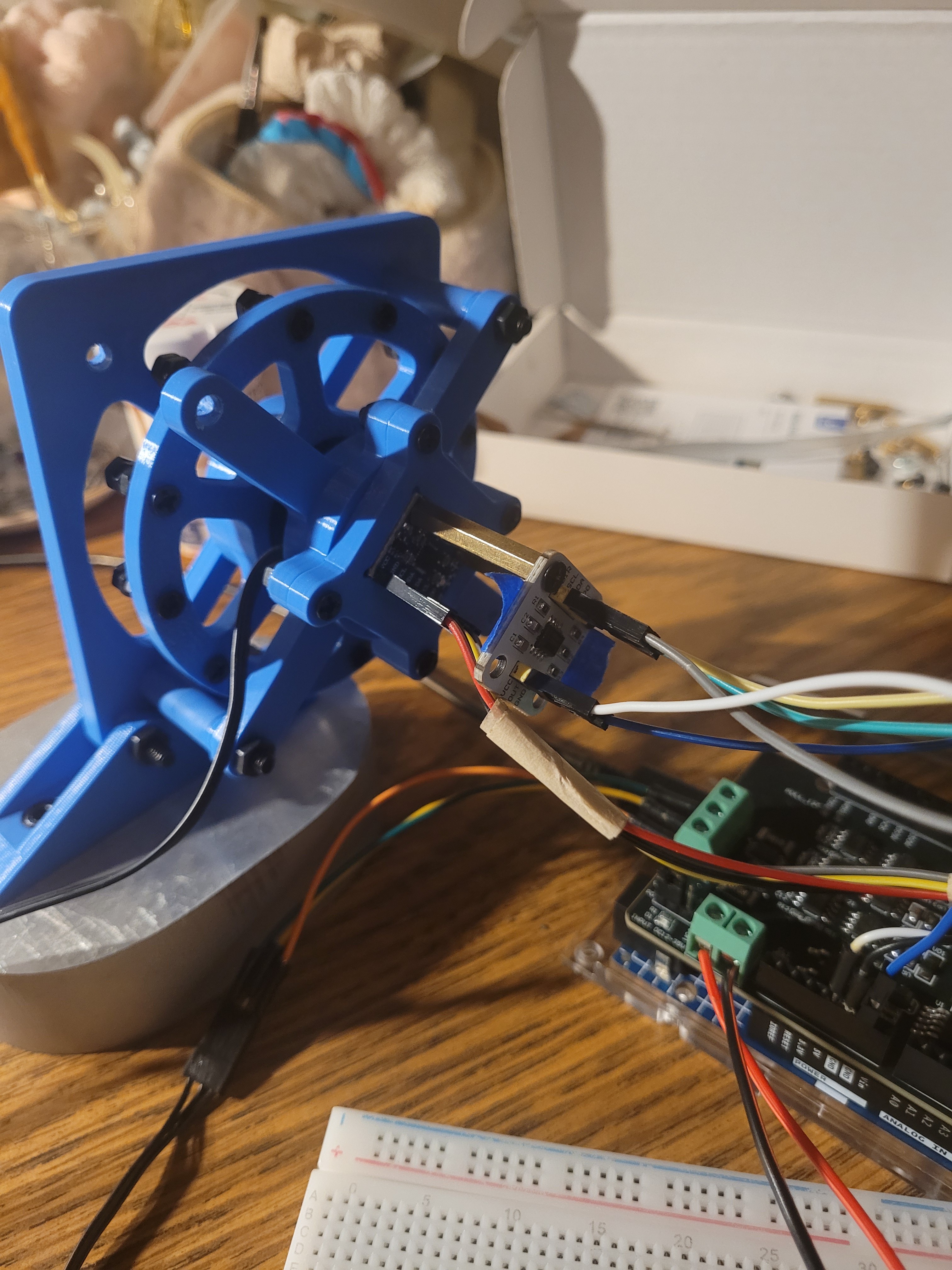
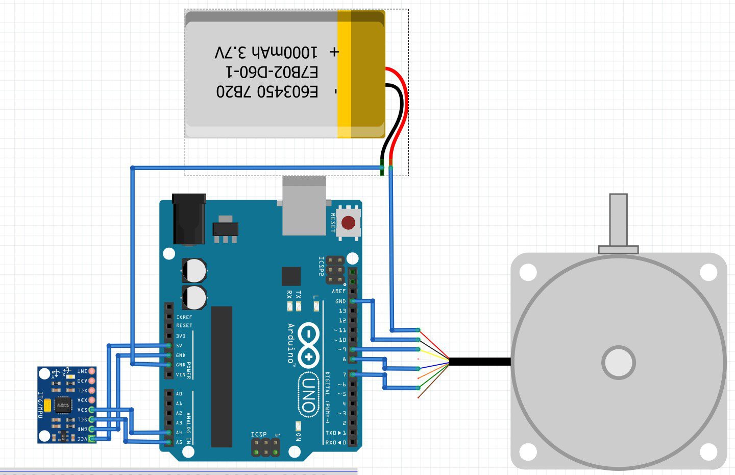
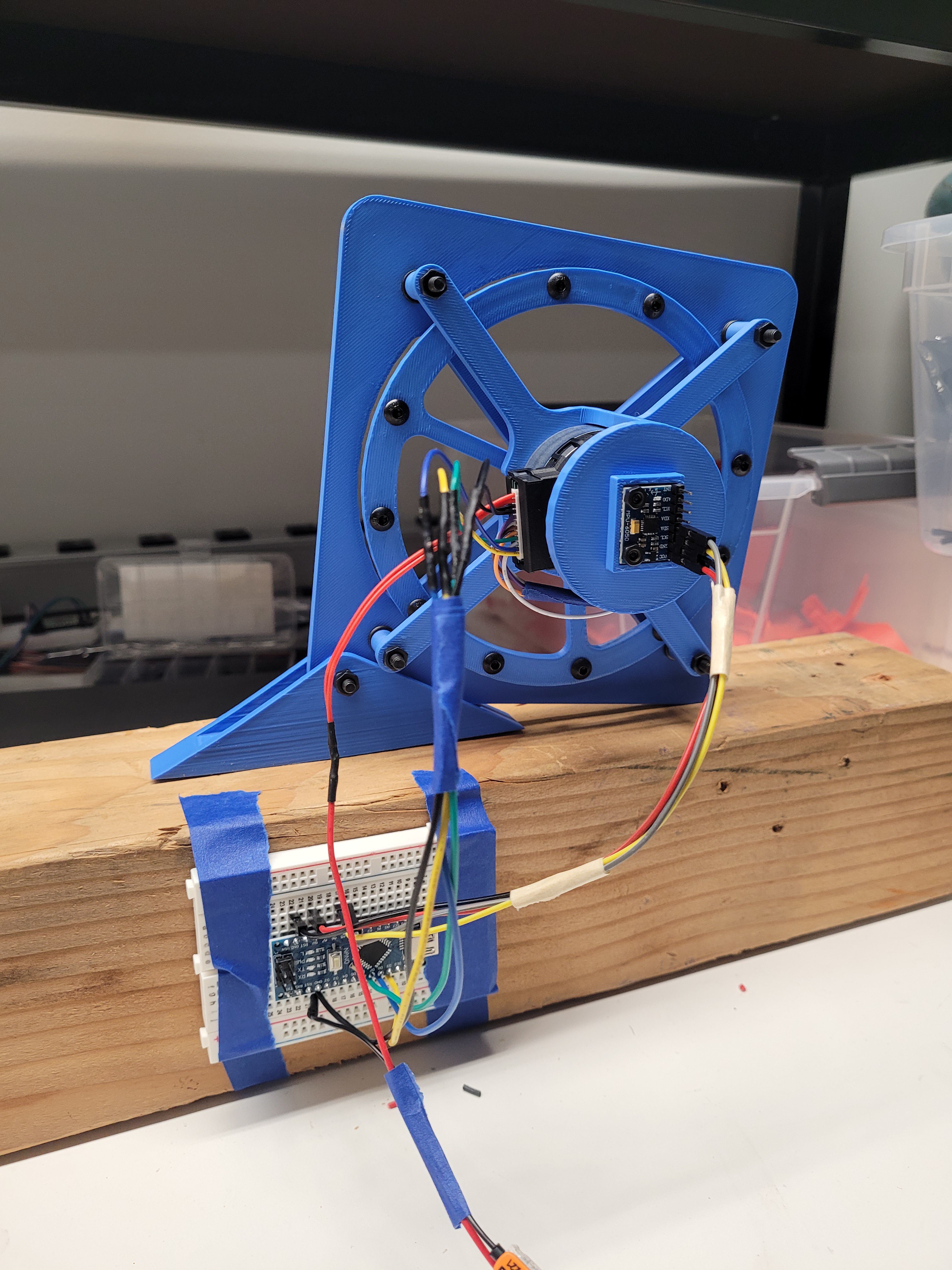
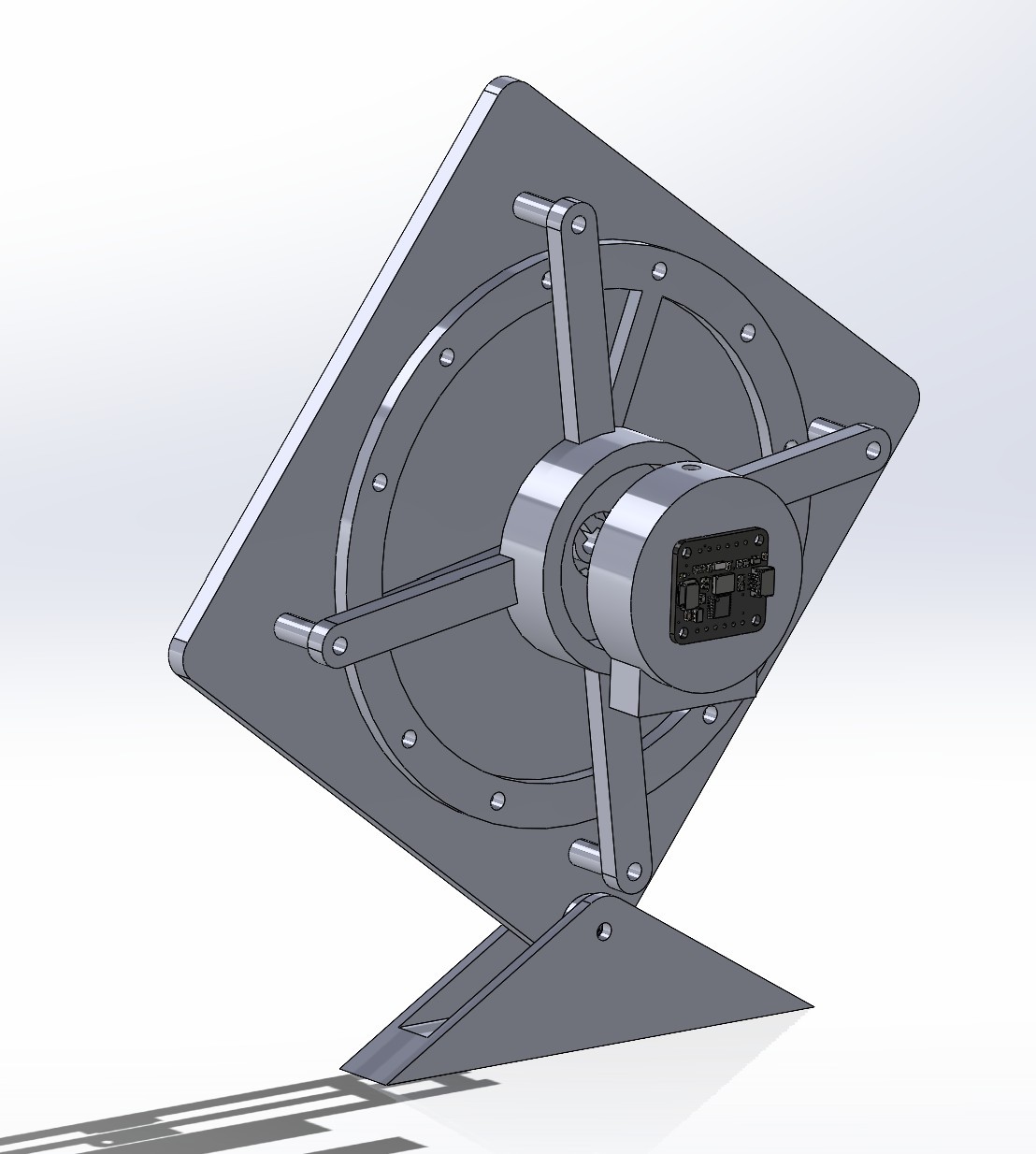
This project attempts to prototype a self balancing cube using reaction wheels. We are in the process of prototyping and testing a 1 DoF test bed that uses only one reaction wheel to balance. We use an IMU to calculate the tilt angle from 0° (upright) and estimate motor speed. We experiment with the reaction wheel's size and weight to provide enough torque to lift the entire platform. When the platform leans to one side, the reaction wheel spins in the opposite direction to self-balance.

v2_3x3_teststand.zip

Solidworks file of parts and assembly

x-zip-compressed - 11.83 MB - 03/22/2025 at 04:28

Download

imu_openloop_test.ino

demo day code (not complete, causes jittering)

ino - 2.38 kB - 03/22/2025 at 03:50

Download

1dof_wiring_mpu.jpg

test platform electronics wiring

JPEG Image - 210.61 kB - 03/22/2025 at 03:49

Preview

  • Demo Day

    Dami Kim4 days ago 0 comments

    Mar 8

    We surprisingly made more progress during the demo

    •  Got the motor to spin in the correct direction and "attempt" a self balance using IMU readings (no video, unfortunately) 
    • Was very jittery and heated the motor
    • Eventually the motor stopped running (we may have fried it)
    #include <SimpleFOC.h>
    #include <Adafruit_MPU6050.h>
    #include <Adafruit_Sensor.h>
    #include <Wire.h>
    
    // Motor setup
    BLDCMotor motor = BLDCMotor(7, 16.4, 90);
    BLDCDriver3PWM driver = BLDCDriver3PWM(9, 5, 6, 8);
    
    // IMU setup
    Adafruit_MPU6050 mpu;
    
    // PID variables
    //float Kp = 15.0;   // Proportional gain
    //float Ki = 0.1;    // Integral gain
    //float Kd = 0.8;    // Derivative gain
    
    float Kp = 10.0;   // Start lower
    float Ki = 0.05;   // Reduce integral action
    float Kd = 2.5;    // Increase damping
    
    float previous_error = 0;
    float integral = 0;
    float setpoint = 0;  // Desired angle (upright position)
    float target_velocity = 0;
    
    // Time tracking
    unsigned long lastTime = 0;
    const float dt = 0.01;  // Time step in seconds
    //const float dt = 0.005;
    
    void setup() {
        Serial.begin(115200);
        Wire.begin();
    
        // Initialize MPU6050
        if (!mpu.begin()) {
            Serial.println("Failed to find MPU6050!");
            while (1) delay(10);
        }
        mpu.setAccelerometerRange(MPU6050_RANGE_4_G);
        mpu.setGyroRange(MPU6050_RANGE_500_DEG);
        mpu.setFilterBandwidth(MPU6050_BAND_21_HZ);
    
        // Initialize motor driver
        driver.voltage_power_supply = 12;
        driver.voltage_limit = 12;
        if (!driver.init()) {
            Serial.println("Driver init failed!");
            return;
        }
        motor.linkDriver(&driver);
        motor.voltage_limit = 12;
        motor.controller = MotionControlType::velocity_openloop;
        if (!motor.init()) {
            Serial.println("Motor init failed!");
            return;
        }
        
        Serial.println("System ready!");
        delay(1000);
    }
    
    void loop() {
        sensors_event_t a, g, temp;
        mpu.getEvent(&a, &g, &temp);
    
        // Calculate angle using complementary filter
        float accel_angle = atan2(a.acceleration.x, a.acceleration.z) * 180 / PI;
        static float angle = 0;
        float gyro_rate = g.gyro.y * 180 / PI;
        angle = 0.98 * (angle + gyro_rate * dt) + 0.02 * accel_angle;  // Complementary filter
    
        // PID control
        float error = setpoint - angle;
        integral += error * dt;
        float derivative = (error - previous_error) / dt;
        target_velocity = Kp * error + Ki * integral + Kd * derivative;
        previous_error = error;
    
        // Apply velocity to motor
        motor.move(target_velocity);
    
        // Debug output
        Serial.print("Angle: ");
        Serial.print(angle);
        Serial.print(" | Target Velocity: ");
        Serial.println(target_velocity);
    
        delay(10);  // Run loop at ~100 Hz
    }
    

  • Week 8

    Dami Kim4 days ago 0 comments

    Mar 2 - 8

    • Kept having motor issues 
    • Decided to use new motors and change design
    • Downscaled to 3" x 3" platform
    • Decided to use Arduino Uno R4 Minima, SimpleFOC motor controller shield, and 2208 90KV gimbal motor
    • CAD-ed, 3D printed, and assembled mini 1DoF testbed and secured it to a metal block
    • Wanted to test out a magnetic encoder for closed loop motor control (and more reliable velocity/acceleration readings)
    • Encoder turned out to be super sensitive and unreliable so we only used IMU data
    • Experimented with reaction wheel mass by adding/removing M3 screws to the perimeter

  • Week 7

    Dami Kim5 days ago 0 comments

    Feb 23 - Mar 1

    • Inconsistent motor connection with the thing motor connector + the wagos (lever nuts)
    • Soldered more wires for reliable conneciton
    • Difficulty controlling the motor when reaction wheel was attached
    • Would inconsistently spin and even when it does spin, would power down and come to a stop even though the same amount of voltage was being output

  • Week 6

    Dami Kim5 days ago 0 comments

    Feb 16 - 22

    • With the help of our mentor (Kevin), was able to control the speed of the motor properly using a potentiometer
    • Finished CAD design of the 6x6" 1 DoF platform that will test self balancing using one reaction wheel
    • 3D printed the platform, assembled it, and secured to a heavy piece of wood block to keep it in place
    • Switched from the BNO08x IMU to the MPU6050 because the BNO took up too much memory from the Arduino Nano
    • Soldered wires for extension

    const int potentiometerPin = A0;  // Potentiometer connected to analog pin A0
    #define PWM_PIN 9      // Yellow - Speed control (PWM)
    #define START_PIN 8    // Blue - Start/Stop
    #define DIR_PIN 7      // Green - Direction (CW/CCW)
    #define BRAKE_PIN 4    // White - Brake (GND = brake, Floating = release)
    
    void setup() {
        pinMode(START_PIN, OUTPUT);
        pinMode(DIR_PIN, OUTPUT);
        pinMode(BRAKE_PIN, OUTPUT);
    
        // Set default motor state
        digitalWrite(START_PIN, HIGH);  // Start motor
        digitalWrite(DIR_PIN, LOW);     // Default: CW rotation
        digitalWrite(BRAKE_PIN, HIGH);  // Release brake
    
        Serial.begin(9600);
        pinMode(9, OUTPUT);  // Set pin 9 as output for tone generation
    }
    
    void loop() {
      // Read the potentiometer value
      int potValue = analogRead(potentiometerPin);
    
      // Map the potentiometer value to the desired frequency range
      int frequency = map(potValue, 0, 1023, 1000, 26000);
    
      // Generate tone on pin 9
      tone(PWM_PIN, frequency);
      Serial.print(frequency);
      Serial.println(" Hz");
    }
    

  • Week 5

    Dami Kim5 days ago 0 comments

    Feb 9 - 15

    • Nidec 24H brushless DC motors arrived
    • Difficulty finding proper documentation
    • Wrote code to make it spin
    • Changed from Arduino Uno to Nano
    #define PWM_PIN 9      // Yellow - Speed control (PWM)
    #define START_PIN 8    // Blue - Start/Stop
    #define DIR_PIN 7      // Green - Direction (CW/CCW)
    #define BRAKE_PIN 4    // White - Brake (GND = brake, Floating = release)
    
    void setup() {
        pinMode(PWM_PIN, OUTPUT);
        pinMode(START_PIN, OUTPUT);
        pinMode(DIR_PIN, OUTPUT);
        pinMode(BRAKE_PIN, OUTPUT);
    
        // Set Timer1 to 20kHz PWM frequency on pin 9
        TCCR1B = (TCCR1B & 0b11111000) | 0x01;  
    
        // Set default motor state
        digitalWrite(START_PIN, HIGH);  // Start motor
        digitalWrite(DIR_PIN, LOW);     // Default: CW rotation
        digitalWrite(BRAKE_PIN, HIGH);  // Release brake
        analogWrite(PWM_PIN, 128);      // Set speed to 50% (range 0-255)
    }
    
    void loop() {
        // Engage brake for 3 seconds, then release
        delay(5000);
        digitalWrite(BRAKE_PIN, LOW);  // Engage brake
        delay(3000);
        digitalWrite(BRAKE_PIN, HIGH); // Release brake
    
        // Toggle direction
        delay(1000);
        digitalWrite(DIR_PIN, !digitalRead(DIR_PIN));
    
        // Gradually increase speed
        for (int speed = 50; speed <= 255; speed += 50) {
            analogWrite(PWM_PIN, speed);
            delay(1000);
        }
    
        // Stop motor for 3 seconds
        digitalWrite(START_PIN, LOW);
        delay(3000);
        digitalWrite(START_PIN, HIGH);
    }

  • Week 2 - 4

    Dami Kim5 days ago 0 comments

    Jan 19 - Feb 8

    • Researched necessary parts
    • Ordered parts
    • CAD designed a 1DoF test bed before attempting to prototype the cube
    • Planned out wiring diagram for electronics

View all 6 project logs

  • 1
    Build Instructions

    Parts

    • 3D printed parts (file attached in project "files" page)
    • M3 countersunk screws
    • M4 bolts/nuts
    • 1 cm bearing
    • Arduino Uno R4 Minima
    • SimpleFOC shield 
    • MPU 6050 IMU
    • 2208 90 KV gimbal bldc
    • AS5600 magnetic encoder (optional)
    • Wires
    • 12V power supply

    Follow CAD file + wiring diagram

View all instructions

Enjoy this project?

Share

Discussions

Similar Projects

Does this project spark your interest?

Become a member to follow this project and never miss any updates