Background
This is a hybrid clock incorporating the elements of a word clock and a digital clock.
That is used to display the time in 12 hour mode.
The display grid consists of 59 numbers, 40 letters and 1 symbol (+), backlit with 100 addressable RGB LED's on a 10 x 10 grid all controlled by a Microbit.
The display grid and supporting display elements are 3D printer
The numbers enable time combinations that exclude the five minute time intervals whilst the letters display the five minute intervals. In addition to the meridiem's represented by A for AM and P for PM.
The layout is such that the numbers may appear haphazard therefore to clarify its type, colour coding is applied.
Subject to user preference or vision colour perception other colours may be used.
The hours are displayed in green the minutes are displayed in red and the meridiem's in blue.
Example times.
14:00 becomes 2 OCLOCK P
14:10 becomes TEN PAST 2 P
03:45 becomes QUARTER TO 4 A
07:09 becomes 7 9 A
20:19 becomes 8 19 P
Display Creation
The information to be displayed determined how many characters were required.
I laid out the characters for the display in Excel first.
A requirement for the display was that the characters should be of a stencil type.
This would require connected negative space to prevent the centres of enclosed characters falling out.
Examples Q,R,O, P, A, D, B, 4, 6, 8, 9, 0
I found a suitable stencil type font: Aero Matics Stencil Font this is a free font from 1001freefonts.com
Next this TTF file needs to be converted to the SVG file, I used convertio.co
I would then require to turn the layout into an STL file for 3D printing.
For this task I used TinkerCAD which has a custom font option involving the following:
Import the font using the Custom font Text and enter the required characters to be formatted and arrange to a 17mm grid spacing to create the display.
CAD Design
The majority of the 3D printed elements were designed using BlocksCAD, with all sliced using Cura 5.8.1 and printed on a Elegoo Neptune 4 Pro.
This project requires a printing bed greater or equal to 206(L) x 206(W) mm.
1: Character Display. 204(L) x 204(W) x 1(H) mm, Weight: 51g
2: Diffuser. Size: 206(L) x 206(W) x 1(H) mm, Weight: 55g
3: Grid. Size: 206(L) x 206(W) x 10(H) mm, Weight: 109g
4: Back. Size: 206(L) x 206(W) x 3(H) mm, Weight: 109g
Print Details
Filament: PLA (Black : Character Display & Grid, White: Diffuser and Grey: Back)
Layer Height: 0.15mm
Infill: 100 percent
Wall Thickness: 0.84mm
Wall line count: 2
Bed Adhesion: Skirt
No supports
All parts are correctly orientated within the files for printing directly.
Operation
Setting the clock.
Before setting the clock ensure that the RTC has a working battery fitted to retain the time when/if power is removed.
The default time setting format is 24 hour mode.
The mode switch (centre off), has two functions time set and Microbit display.
With the switch in the centre position both the set mode and Microbit display are disabled.
In one position, set mode is enabled and the Microbit display is enabled during setting.
In the second position, set mode is disabled and the Microbit display is enabled for time display.
Being able to blank the Microbit display serves two purposes, 1: to save power, 2: as the Microbit is mounted at the back the Display will not be visible therefore it only needs to be visible when setting and verifiying the time.
Move the mode switch to the set time position a plus symbol will be shown on the display.
Press Button A for Hours. (0 to 23)*
Press Button B for Minutes. (0 to 59)*
*Each press incrementing the number to the maximum value and on the next press resetting to zero.
Press Buttons A & B together to set the time, the entered time values will be displayed.
Move the mode switch from the set position either to the centre or Microbit display enable.
With the mode switch in the centre...
Read more »
 Ricardo Sappia
 kmatch98
 Fabian
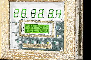
 brett.oliver