Yann Guidon / YGDES
-
Better working prototype
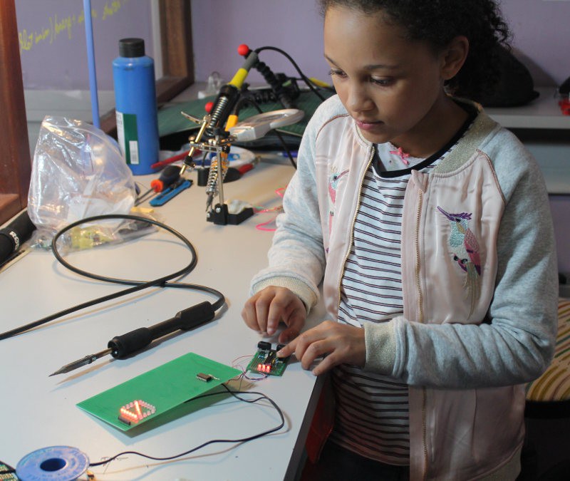
03/30/2017 at 02:39 • 0 commentsToday we were able to finish 3 segments (2×6LED and 1×4LED, with their 330 Ohms series resistors) and the signal generator so we added the '595.
![]()
The signal generator helps us control the segments in real time so we could measure the currents. The procedure is easy when there is no 595: just insert a milliampmeter between the power supply (5.5V when open) and the desired segment. We found 13mA for 6LED and almost 10mA for 4LED segments. That's more than what we calculated and rated !
Since the 595 can supply at most 70mA, each segment should draw at most 70/8=9mA. But there are two factors that make this measurement misleading :
- The PSU is barely loaded and drops to 5.4V when mildly loaded. We calculated for 5V, yet here we get +10% bonus.
- The '595 has some inner resistance for each data pin so the segment voltage will be lower.
- The '595 has a single power pin through which all the current goes, which adds more resistance : more lit LEDs will drop the segments' voltage even more...
3 is why we need to turn ALL the segments ON at the same time to make meaningful measurements. For now we have only 3.
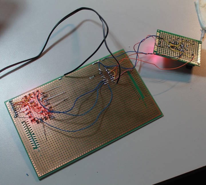
![]()
When the '595 is soldered we can't insert the milliampmeter in the signal. However we can measure the current indirectly by reading the resistor's drop : I=U/R.
We get about 1.4V/330=4mA per pair of LED, which is the expected value : 6LED should be about 12mA and 4LED should be about 4mA. This gives an average of 10mA/segment, which will slightly drop as the PSU voltage reaches 5V and more segments are turned on (they are not all ON at the same time)
So this incomplete prototype has shown that the design goals are met but we need to test with ALL the segments at the same time for a definitive measurement.
Anyway we finally have something to play with !
-
A little progress
03/23/2017 at 17:46 • 0 commentsSome segments start to work :-)
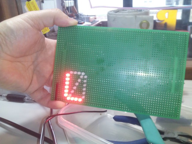
![]()
The light looks nice :-) It will be better on a black background.
Many segments are still missing but we can at least test the resistor networks. Half of the segments are required to test the circuit with one 74HC595.
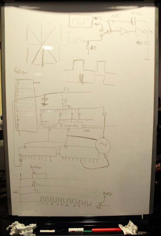
And the signal generator is taking shape, it can generate a 5Hz signal or single pulses to help test the boards.
I had to revise the resistor values because the original, theoretical values were wrong...
![]()
Still missing: another debouncer for the data signal.
-
Little by little
03/16/2017 at 03:45 • 0 commentsSmall steps...
![]()
The system is getting better defined, a we're trying to make an all-circuit controller.
We're also building a final prototype with the definitive parts, and the new LEDs are superior to the old we used before, as they "sit" directly on the PCB and require much less adjustments of position.
![]()
That means : a lot of time will be saved when 4200 of them will be manually assembled !
-
Parts
03/14/2017 at 05:46 • 0 commentsHere I discuss about the main parts used by this project.
- 74HC595 : that's the 8-bits shift registers, 2 are required for each module so overall 50×2=100 are required for the whole project. For simplicity reasons, it is used in dump SPI mode, with no additional latch signal, because we don't care about the looks when the display is updated. On the contrary, shifting all the segments can create a cool effect for no cost !
Stock: OK, from personal stock (a stupid display project from 2009) - LEDs:
- must be red/yellow/green because the forward voltage drop is lower and 2 or 3 can be wired in series. New green or blue LEDs require more than 2.5V, more resistors and more soldering...
- 3mm is chosen because 5mm is a tiny bit too large. We have tried several models (from old stock) and chosen new diffused flat-top model with nice look and color (but slightly higher voltage drop)
Stock: OK, bought specially for this project on eBay. - Resistors: individual resistors require too much soldering, despite the choice of red LEDs that cuts the numbers in half. There are still 50×42=2100 resistors to solder, or 4200 joints ! I have found the solution : SIL resistors modules.
Each display module has 84/2=42 resistors, which is not a multiple of usual SIL models so a composite method is used : 2× 10-pins SIL with 9 resistors make 18 resistors, the remaining 24 are made of 3 SIL with 9 pins and 8 resistors.
Value has been experimentally determined to 300 Ohms
Stock: OK, bought specially for this project on eBay. - DIP switches : 2× standard cheap 8-switches for the data, and 1-bit switch for the mode.
Stock: OK, bought specially for this project on eBay.
Other parts (capacitors etc.) are common and do not require a particular consideration.
- 74HC595 : that's the 8-bits shift registers, 2 are required for each module so overall 50×2=100 are required for the whole project. For simplicity reasons, it is used in dump SPI mode, with no additional latch signal, because we don't care about the looks when the display is updated. On the contrary, shifting all the segments can create a cool effect for no cost !
-
Tonight's idea...
03/11/2017 at 18:19 • 0 commentsAfter I created the project page, I was thinking about the boards that require development : the alphanumerical module itself, of course, and the small test board that sends the clock pulses during testing.
Then there is the question of how to drive the 50 modules and display messages.
One obvious solution is to use a Raspberry Pi with some sort of web interface (driven by the #micro HTTP server in C for example) but the workshops are about electronics, not computing or programming !
Then it occured to me that it's totally fine to make a "semimanual" keyer that generates the required pulses when pressing on a given button...
Of course the "normal approach" is to use an Arduino (or Pi) to scan a keyboard, and transform the keycode into a 16-bits synchronous serial stream. But the kids wouldn't learn much and programming would confuse them a bit.
It's more interesting to generate the bitstream with hardware, particularly with a couple of 4017 and a large diode matrix : everything is exposed, with LEDs showing the paths of signals. This requires a significanly large PCB but this can become a fun subproject on its own for the last months of the workhop.
Of particular interest is the circuit that generates exactly 16 pulses when a button is pressed. I have not yet figured it out completely but it's going to be very interesting. The 4017 can indicate when all the pulses have been sent to inhibit the clock but a single press of the button must send exacty one character, regardless of the pulse duration.
Oh and I'll have to find nice buttons for the front plate, if possible DPST because a single press must both route the signals from the diode matrix, and start the oscillator.
Another approach doesn't use a 4017 but 74HC165 parallel-in shift registers. There is still diode ROM but it is driven "backwards" compared to the 4017 version.
A single push of the button will drive diode to 1) decode the data to send 2) start the oscillator. This way, only SPST buttons (classic !) are required. The kids can play with the diodes to generate the desired letter shapes. The '165 can latch all the 16 bits during a single clock cycle then shift them out later, when the button is released.
dual-mode 16-segments LED display module
A project I develop with the kids for H1 2017 at CercleJ.