 Michael Gardi
Inspiration
For some reason the mysterious YouTube algorithm started adding "restoration" videos to my feed. There are a lot of practitioners posting their amazing work making old things new again. In general I find the flow of these videos very relaxing. There is typically no dialog, just the sounds and video of a competent craftsman going about their business. The before and after images are remarkable.
I don't know why the video "Restoration of a 1920s horse racing game GeeWIZ" by MW Restoration caught my eye, but I'm glad it did. I mean I am interested in vintage things, but typically computer related not toy related. Never-the-less I watched the whole video and if you made it this far I would recommend that you do too.
There were many interesting facets to the video, but a few that jumped out at me.
- This person has some very cool tools.
- Sand blasting the old paint and rust off of the parts was fascinating. I had never seen this done before and to me it was like magic.
- The cleaned up parts were then powder coated. Again another process that was new to me. I liked the way the author (editor) would cut the scenes of the dull powder instantly melt and flow, forming a solid, shiny, durable coating. (My understanding is that tis process takes some number of minutes.)
- And finally at the end, with the GEE-WIZ completely and beautifully restored, the author wound some string around the the shaft adjacent to the flywheel and pulled. Immediately the horses started lurching up the incline in fits and bursts.
It was at that point that I sat up and said WTF. How was this happening? Needless to say for me the hook was set.
The Little Engine That Could
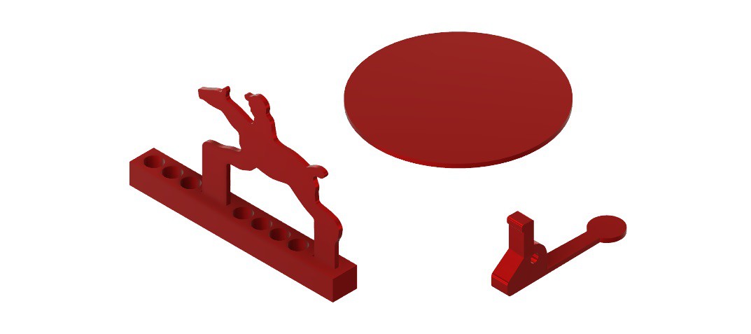
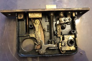
The mechanism for propelling the horses up the incline is both simple and elegant. A flywheel is attached to a shaft that is square on one side and round on the other. The round part has a hole drilled through and a "washer like" disk attached near the end of the shaft allowing a string to be threaded then wound around the shaft between the flywheel and the disk.
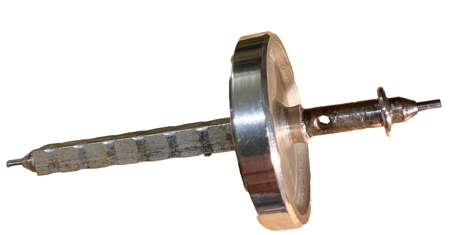
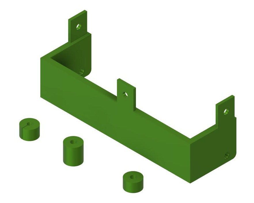
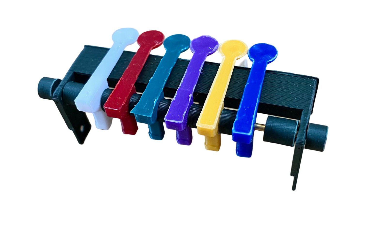
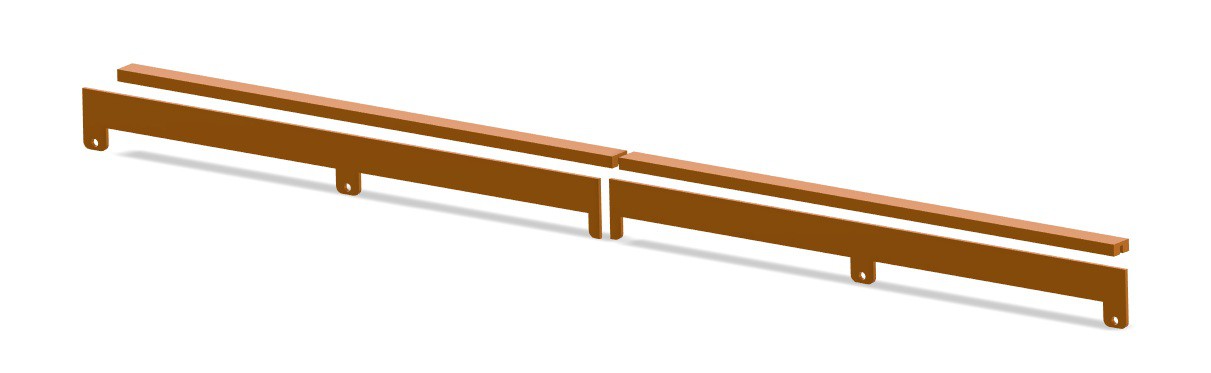
The square part of the shaft sits at the lowest part of the incline below six channels that represent a straight race-track. Each channel holds a sheet-metal outline of a horse and rider which sit on top of a "sled".
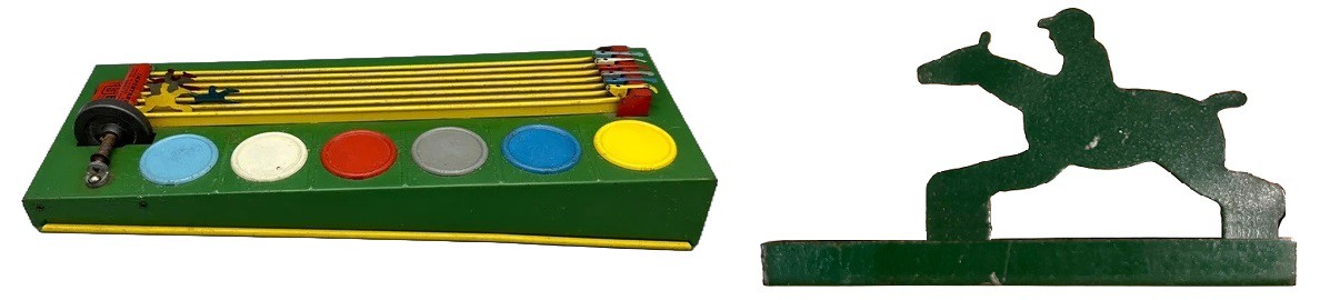
A "race" is started by winding a string onto the axle which is mounted by the starting line, and pulling it to spin the flywheel. Each channel contains a captive ball-bearing which, when struck by the angled faces of the square shaft, is thrown against the horse sled, pushing it forward. The ball then rolls back down the incline until it reaches the axle and is again thrown uphill along the channel to hit the horse sled. Here is a patent for the GEE-WIZ.
I was lucky enough to find a GEE-WIZ on eBay for a reasonable price that was also in really good shape. The "engine" image above is from my unit. You can see that it has been well used. Here is my GEE-WIZ in action right out of the box (no restoration required :-)
Remarkable given that the game is at least 80 years old!
Planning
I knew that making a GEE-WIZ would involve reproducing the flywheel based engine. Only one problem there, I have never done any metal work. The makerspace that I am a member of (Kwartzlab) has a well appointed Machine shop, and talented members that can help me get going, but I get the impression is that the GEE-WIZ "engine" isn't exactly Machining 101.
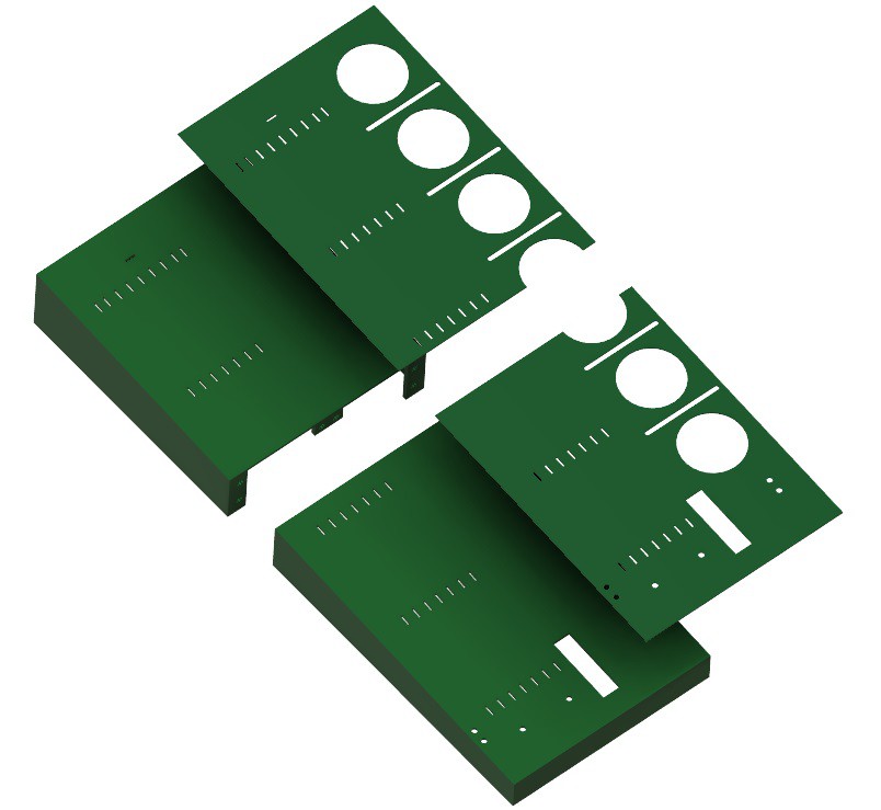
One of my lab mates pointed out that PCBWay now offers CNC Machining. Like their PCBs, they offer an Instant Quote feature where you can upload a STEP file of your part, choose your material (steel, copper, aluminum, etc.) and finish, and get an estimate of the cost. So I created a model of the flywheel engine in Fusion .
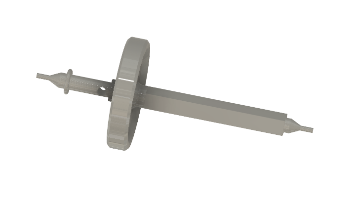
I uploaded the model's STEP file to PCBWay, chose stainless steel as my material and a quantity of 1 and here is a screen shot of a quote produced.

There is one caveat though. Its a...
Read more »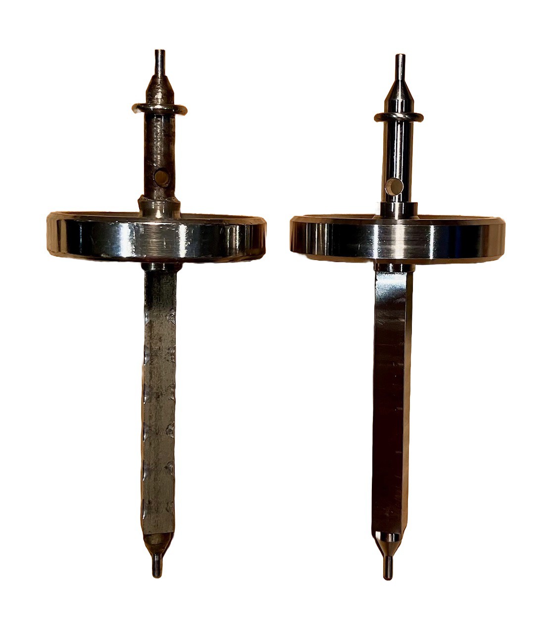
 Jeremy
 Sarah Petkus
 MasterOfNull
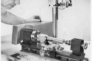
 Jose Ignacio Romero