 JP Gleyzes

Introduction
As an intro, here is a video showing the system working.
Following of this page will explain how it works and how to build one.
A little theory
To find the Center of Gravity of a plane (or anything else) you just need one scale and a ruler !
You will need to know the total weight of the plane and measure a moment from the leading edge of the wing:
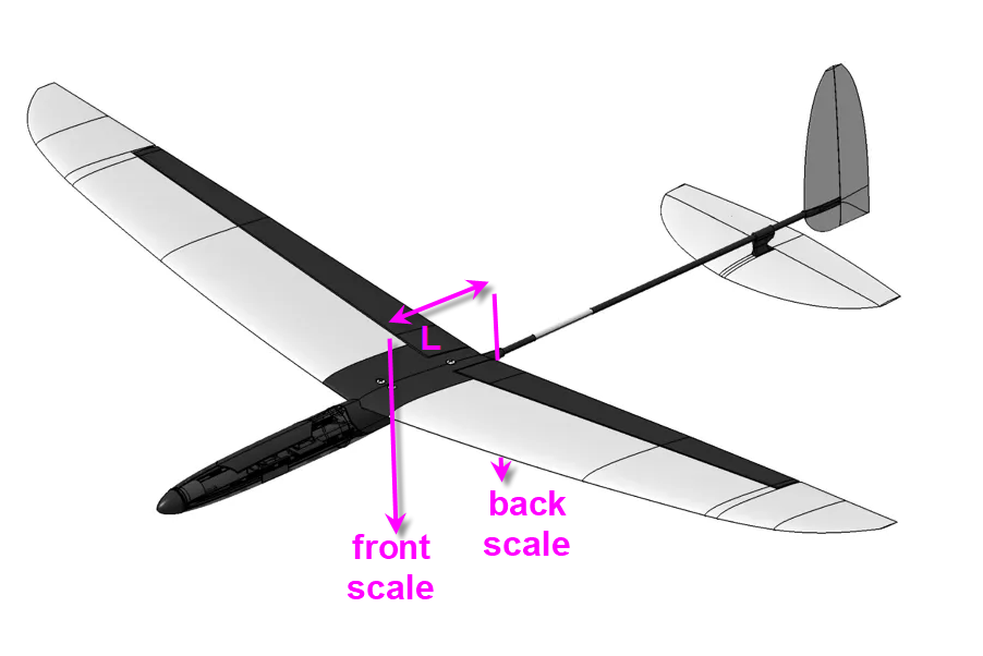
if W is the total Weight, Wb the weight read on the back scale and L the length of the lever between front and back pivots, then
or
CoG is the distance between leading edge and the center of gravity point. Generally this point is around 1/3 of the average wing chord.
This was the easiest solution when you have a single scale. Building such a device was extremely easy and is explained here : a "manual" CoG finder on thingiverse
The main "drawback" of this system is that it requires to weight the plane and then compute the formula anytime you change something into the mass of your model.
So I decided to add a second digital scale and a micro controller to have something more automatic !
When you have "front scale" and "back scale" weights (Wf and Wb) then the formula to find the CoG position relative to the leading edge of the wing is:
That's frankly easy and the electronics to build such a system should be simple as well.
Electronics schematics
- the heart of the system is a Lolin32 lite ESP32 MCU.
- and 2 load cells + HX711 amplifiers are needed as "digital scales"
- an Oled display is optionnaly added (if you don't have an Android phone !)
- a rotary encoder can help to tune values (if you don't have an Android phone)

And that's it... not complex at all !
Bill of Material can be found here :BoM file
PCB
I have designed a nice and compact PCB allowing to fit the ESP32 and to connect all the sensors

The PCB was kindly sponsored by PCBWay and is as usual of excellent quality.

You can order it here: PCBWay shared project.
I must admit that this PCB is probably one of the simplest I have ever designed, but It's so cheap, delivered so fast and so professional looking that it worthed the time spent to design it !
And if you are new to PCBWay please use this affiliated link : https://pcbway.com/g/o35z4O
Power considerations
To power this board I will simply use an USB chord plugged into the ESP32 connector on one side and on any 5V power bank on the other one !
The lolin32 is equiped with a 3.3V linear regulator strong enough to deliver 1A current. Fairly enough for two loadcells and an 1" LCD !
LoadCells
I have choosen two 2kg loadcells. This is a good balance between sensitivity an max load. Most of my planes are gliders in the range 200g to 3kg. As the total weight of the plane is almost shared on the two scales, 3kg will put max 1.5kg on each scale... 2kg load cells add some safety margin !
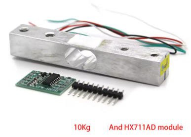
These devices need an amplifier HX711 to adapt their output.
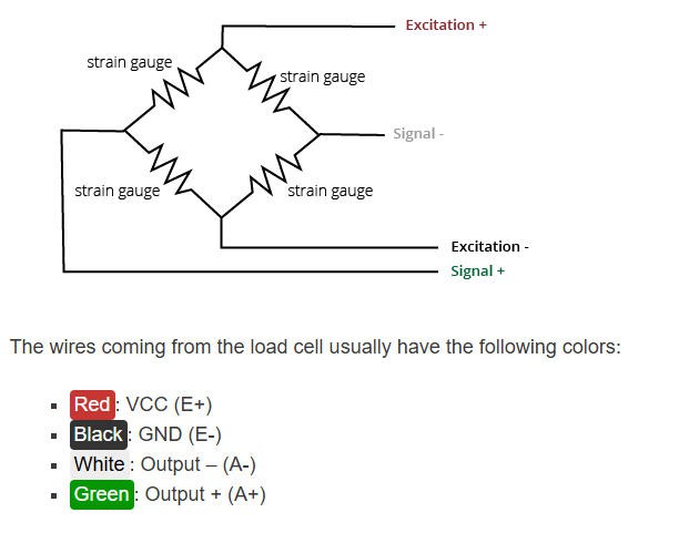
Connection between load cell and amplifier follows this schematics:
Plane stand and scales
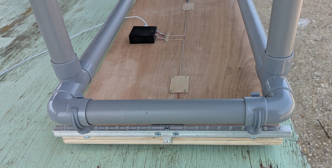
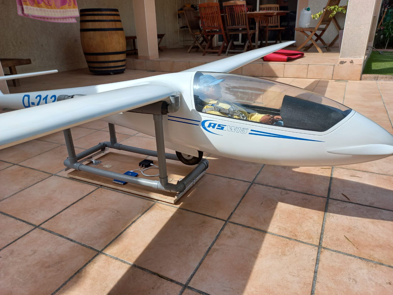
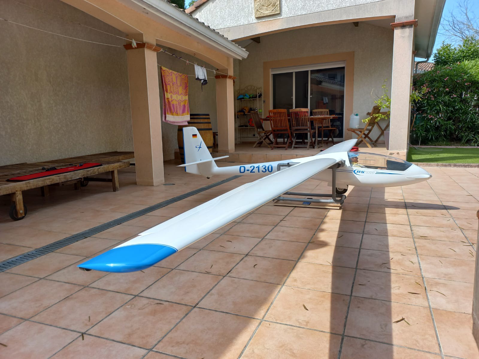
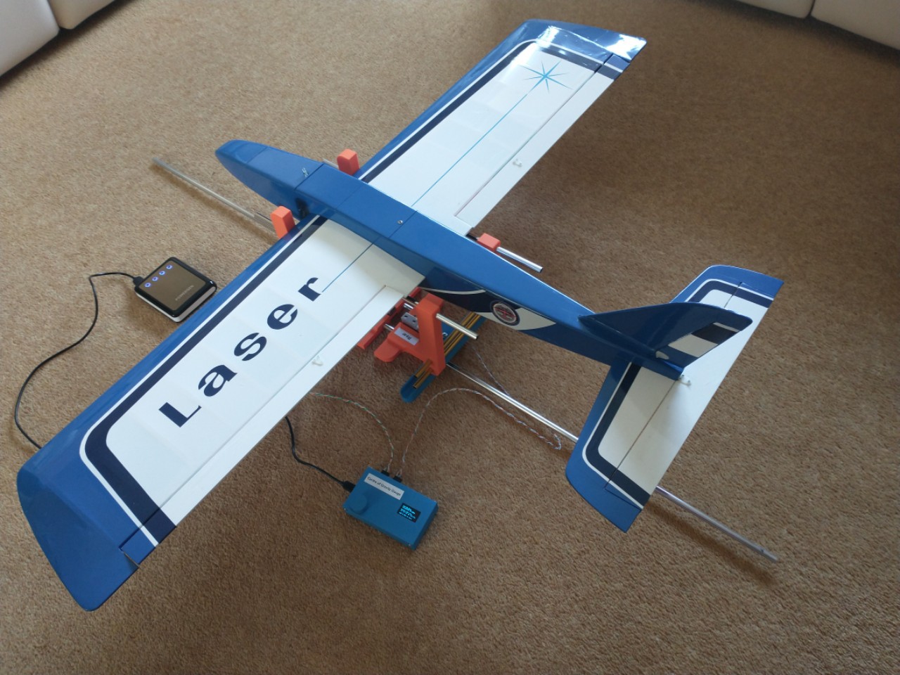
The plane will be sitted on a stand, its wing leading edge touching the vertical side of the stand.
The stand itself will be put right above the two loadcells. Perpendicularity of feet must be insured so that the horizontal bars of the stand are trully horizontal. This is mandatory for accuracy of the "moment" computation
Both the stand and the scales must be adjustable in width and lenght to accomodate most of the RC planes.
building the stand

As you can see the length "L" is measured between the two vertical sides of the stand.
Here is the stand with a small foamy flying wing:
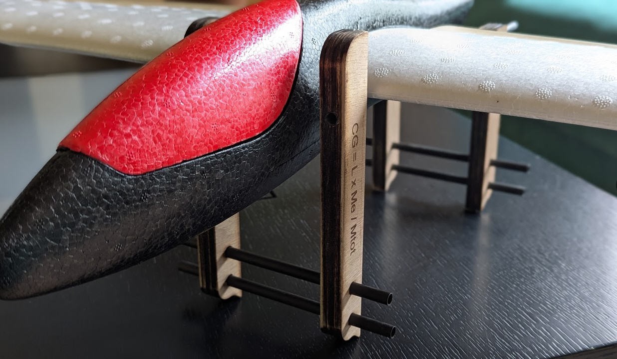
The stand can be 3d printed or laser cut. Both options are available.
If you choose the laser cut option (what I did) then cut the “CoGfinder_flat.dxf” file into 5mm plywood. Then glue each foot with 3 parts (the slot one in the middle). Let the glue dry and drill the...
Read more »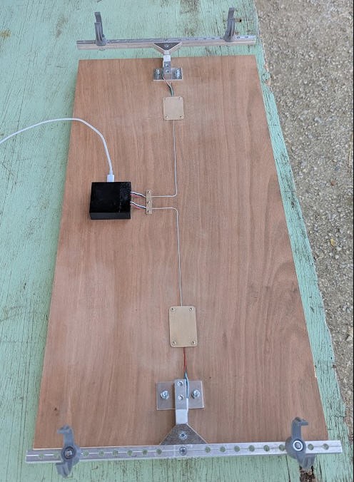



 Udi Tirosh
 Martin Fasani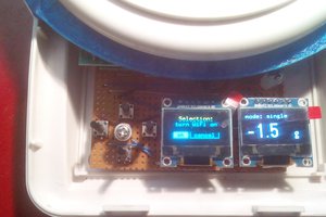
 uri.shani
Hi,
Thanks !
It's a NurfLidl. I derived mine from this site : https://www.rc-network.de/threads/nurflidl-modidfizierter-lidl-xl-glider.677669/page-17