 Victor Barahona
Main features:
- Two-piece PLA chassis that are joined together using 4 M3x10 screws. Includes hook to hang it from the neck or hand.
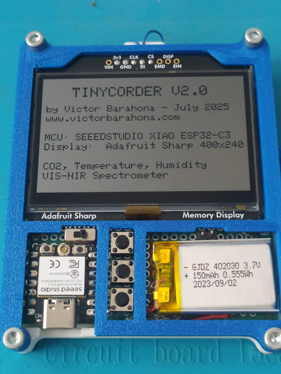
- XIAO ESP32C3 MCU from Seeed Studio.
- 150mAh Lithium Ion battery.
- Power switch and 3 pushbutton for interface (Up, Down, Enter).
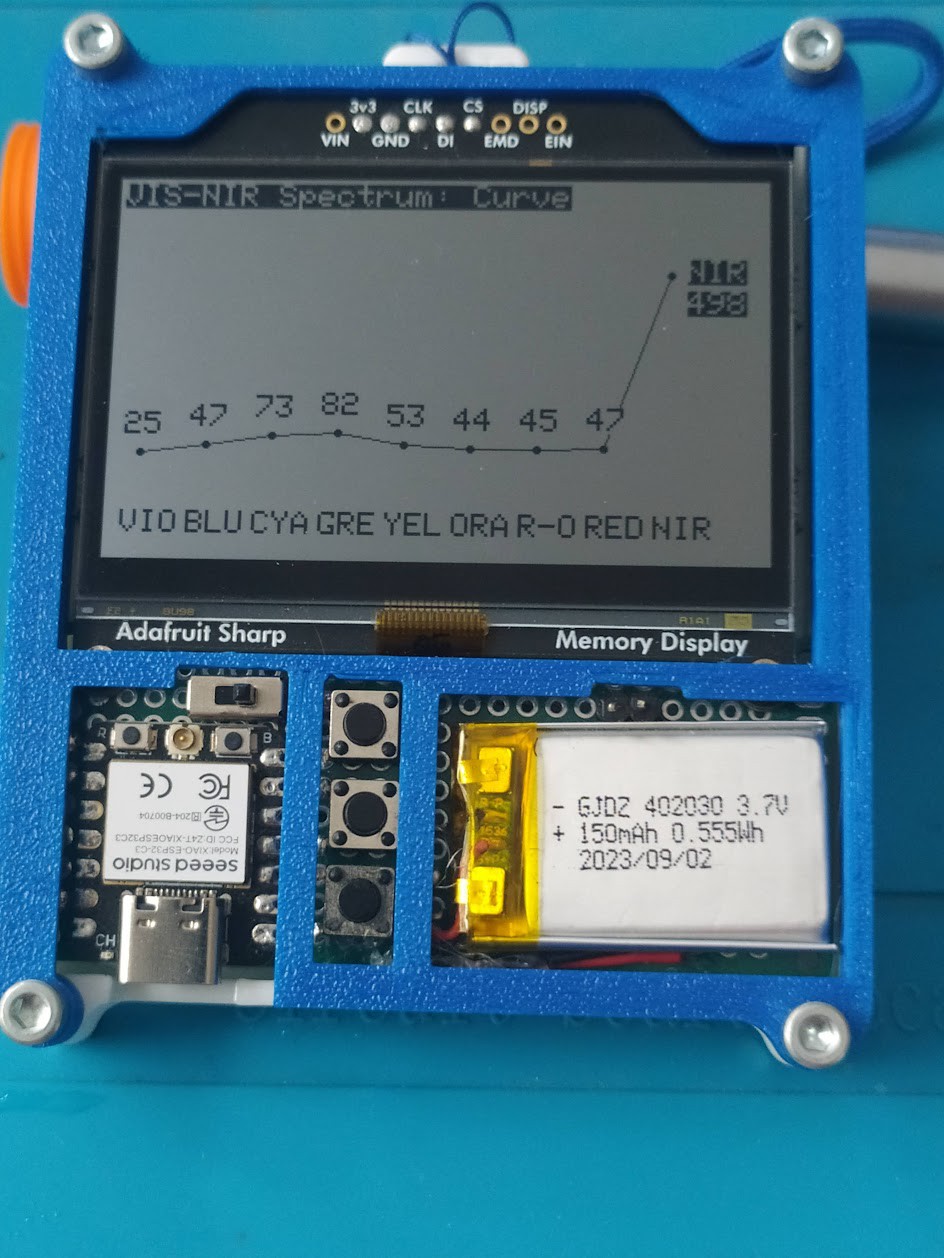
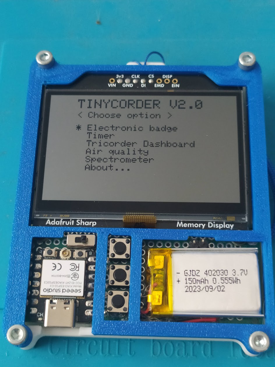
- Sharp Memory Display 400x240px from Adafruit. Very low consumption.
- AS7341 sensor for light measurement in 7 visible and NIR (near IR) bands.
- SCD40 sensor for measuring air quality and CO2.
- BMP280 sensor for measuring temperature, humidity and pressure.
- 2 free pins accessible from the front to measure analog signals.
WORK IN PROGRESS


 Sebastian
 Juan Albanell
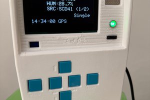
 Apollo Timbers
https://youtube.com/shorts/ru9a2Mq4lZI?si=55Z1NvpCbkOlePjX