 Arnov Sharma
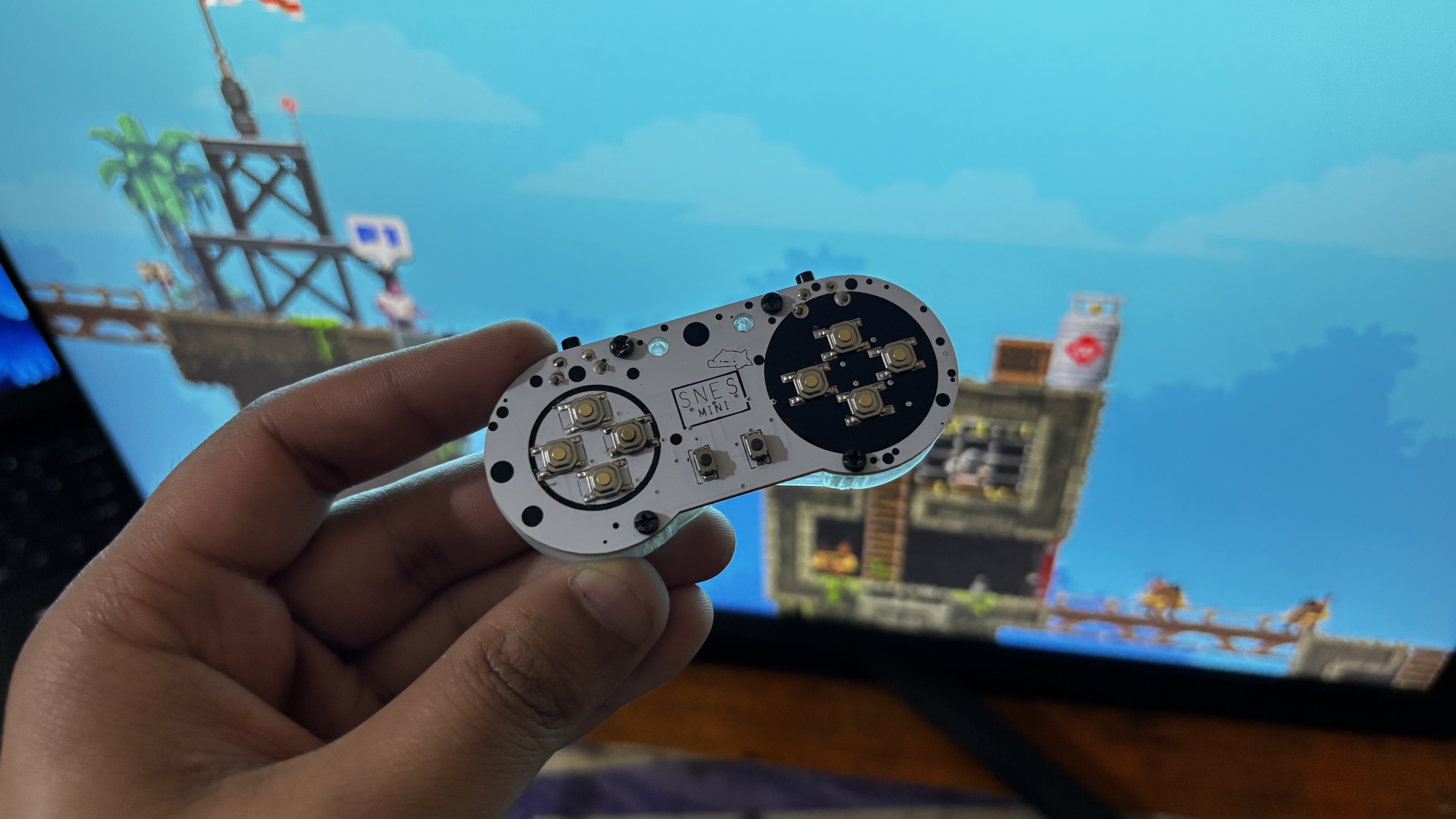

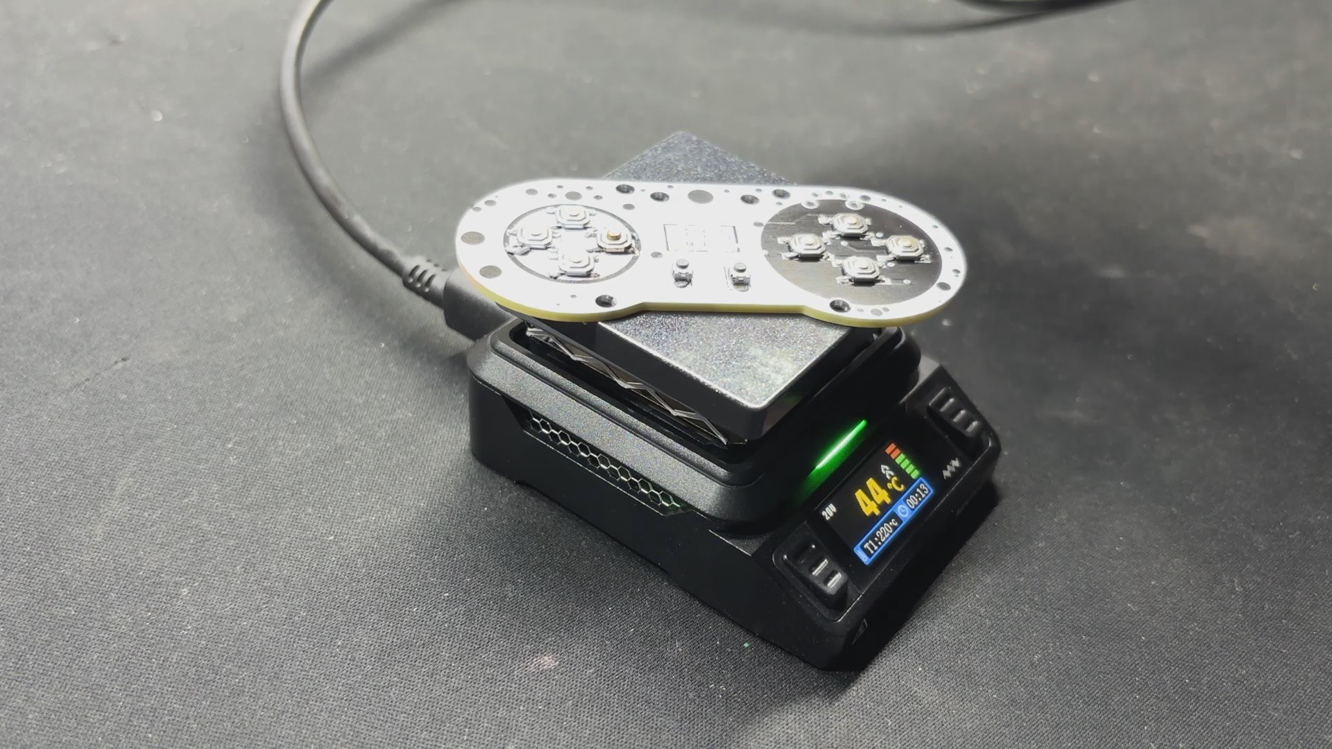
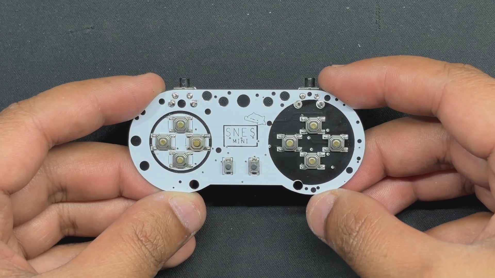
For the smaller version, I intend to use the RP2040-Tiny mini development board, which is an SMD or Module version of the Raspberry Pi PICO. This RP2040 Tiny Module was mounted on a controller-shaped PCB with Small SMD tactile buttons on one side and the RP2040 controller on the other. To improve the controller's grip, I added an enclosure attached to the bottom side of the PCB, making it comfortable to hold.
Despite its small size, the Pocket SNES works fairly well. We initially used the controller to play Broforce; we had to map its buttons to control our avatar or character. Basically, we can use this controller in any game; we simply need to map the keys.
Next, we tried this controller with our MAC Pi setup, and I played a few games on the PPSSPP emulator, including Moto GP 3 and Dead or Alive Paradise. In this case, we also had to map the controller in the PPSSPP Emulator settings.
Overall, this tiny controller works similarly to a standard-sized SNES controller, with 12 buttons. The best part about this project is that we can finish it in a few simple steps because it is just a PICO connected with 12 buttons.
DESIGN


We begin by creating the project's model, which was a major challenge.
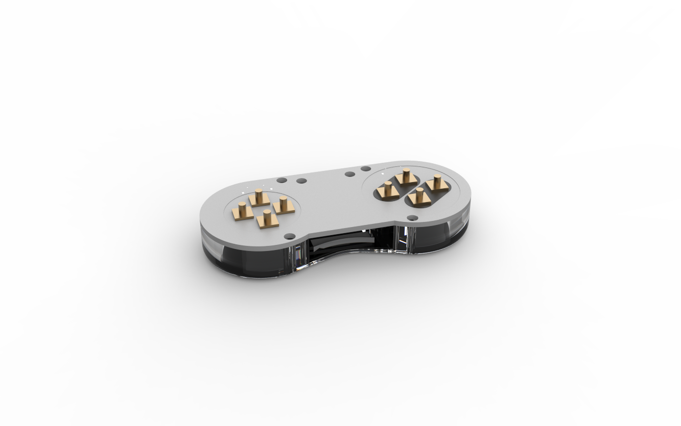
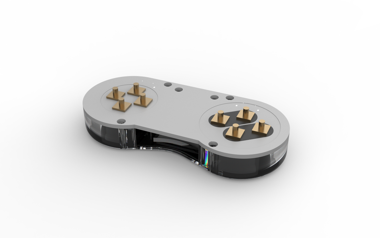
We created an XL version before developing the Tiny version. The XL version has an unrestricted area, allowing for unrestricted component layout without regard for space.
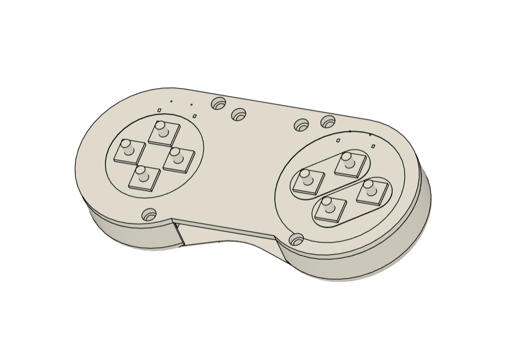
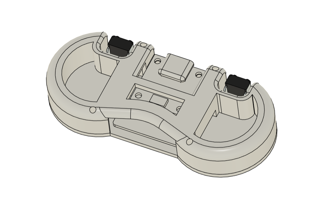
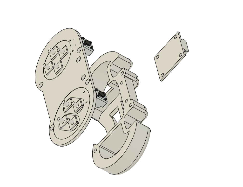
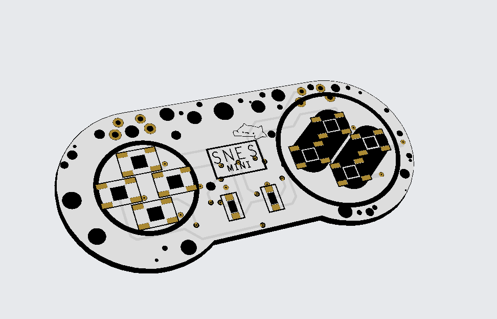
In our Tiny version, the initial idea of assembling an enclosure and placing components inside proved impractical. Instead, I designed a PCB that accommodates all components on both sides, with a frame-like part attached to the bottom. This frame provides protection for the adapter board and improves user grip.
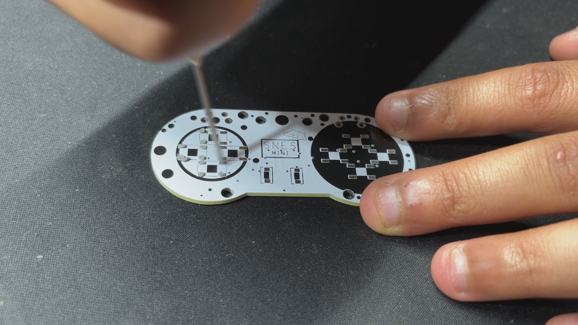
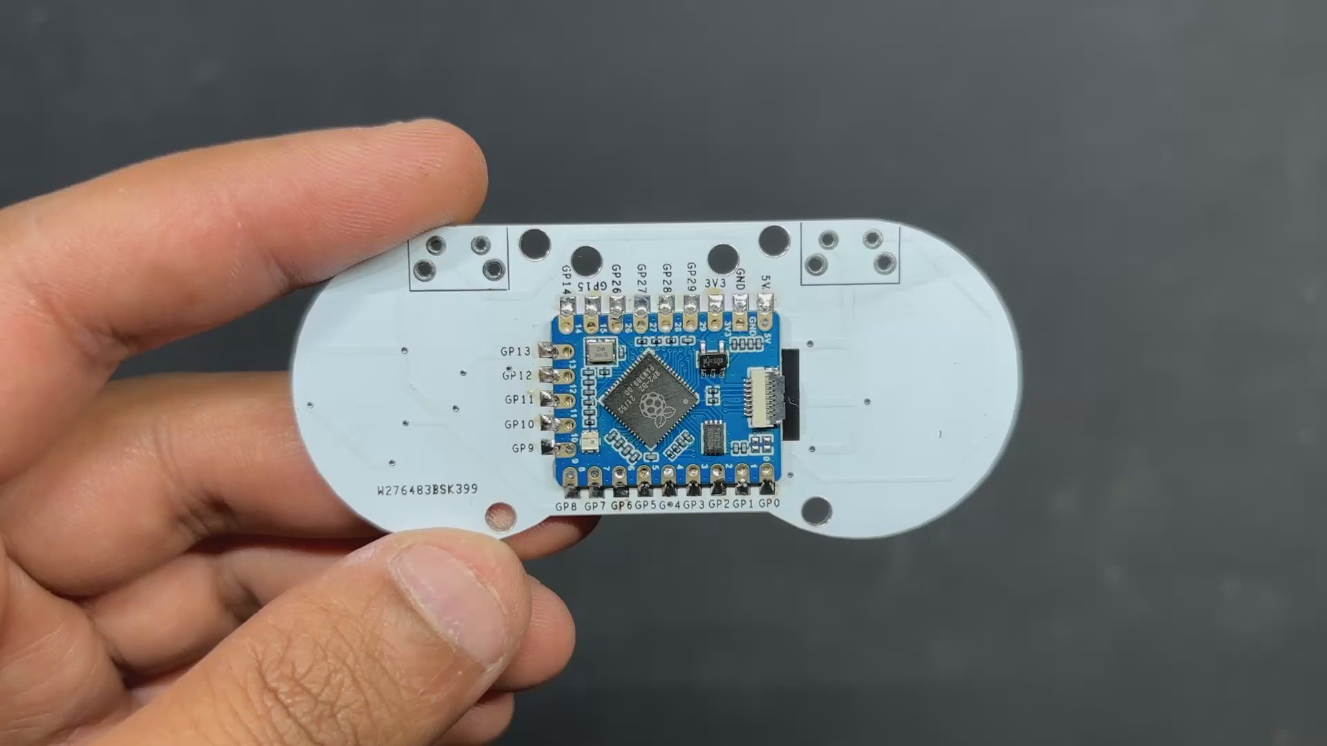
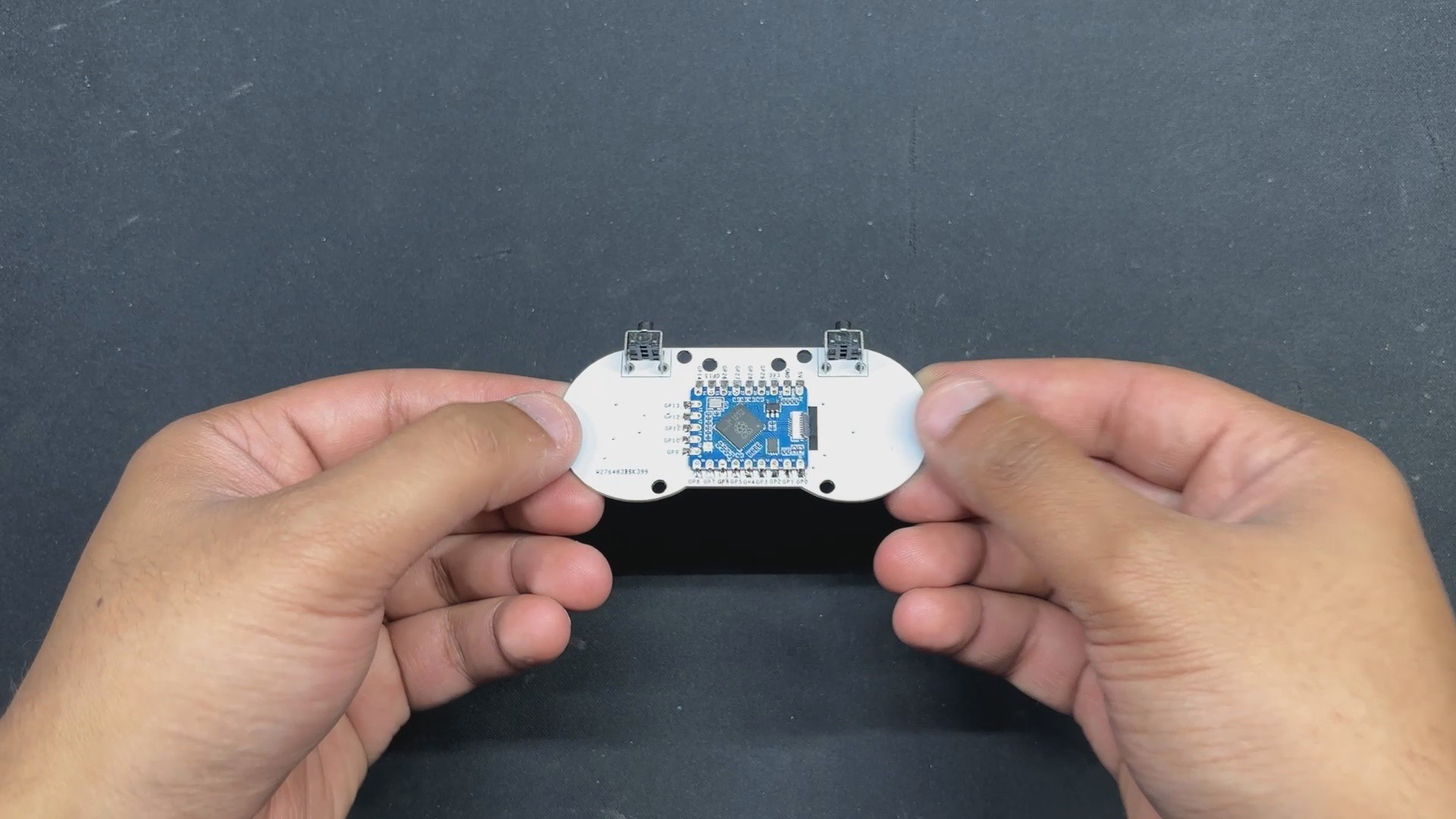
The SMD buttons are positioned on the top side of the PCB, while the right-angle tactile switch and the RP2040 Tiny Dev board are placed on the bottom. The USB adapter board is mounted on the back, secured by screw bosses integrated into the frame.
Once the model was finalized, we exported the mesh file for 3D printing using transparent PLA, allowing the onboard RGB LED to illuminate through the material. Additionally, the board’s DWG file was exported for use in the PCB editing process.
RP2040-Tiny micro development board
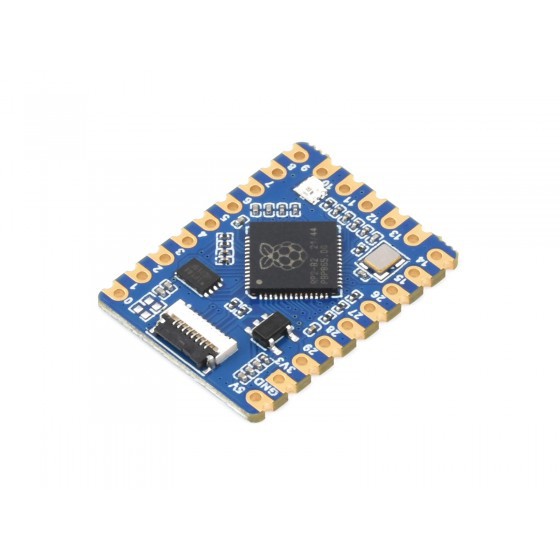
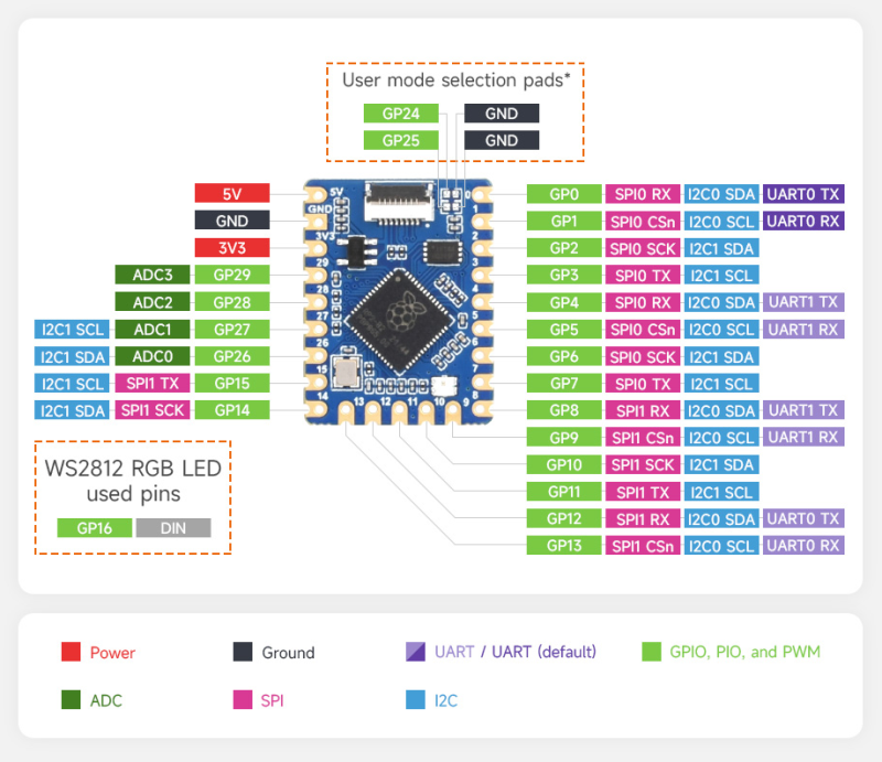
We are using the RP2040-Tiny mini development board, which is based on Raspberry Pi's RP2040 core. It includes a separate programming adapter board that keeps the type C USB port separate from the circuit, reducing overall thickness and size, making it easier for users to integrate into their projects.
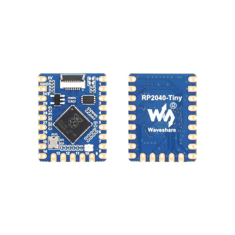
In terms of technical specifications, it's essentially a Pico with an RP2040 microcontroller chip and a few modifications, such as the Onboard FPC 8PIN connector, which connects the module to the Type C adapter board, and the addition of Castellated holes or pads, which allow soldering directly to carrier boards.
We also have a WS2812B 2020 Package LED added on the board, which is connected to GPIO16.
Overall, this board shares its technical parameters with PICO 1, which includes the RP2040 Dual-core Arm Cortex M0+ processor, flexible clock running up to 133 MHz, 264KB of SRAM, and 2MB of onboard Flash memory.
For in-depth details about this Dev Board, you can check out its Wiki Page fropm the link below.
https://www.waveshare.com/wiki/RP2040-Tiny
As for where I got it, we got it from PCBWAY's Gift Shop, which is an online marketplace for getting electronics modules and dev board sensors at their genuine pricing, or you can get them through PCBWAY's Reward system known as beans.
Checkout PCBWAY's Giftshop from here
https://www.pcbway.com/project/gifts.html
PCB DESIGN

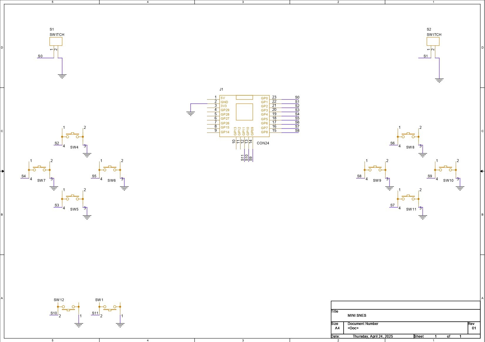
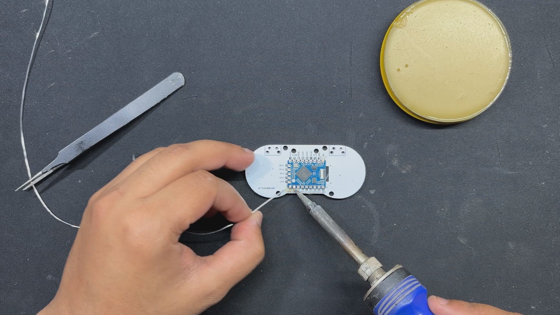
As previously stated, the PCB design for the Game Controller was truly simple; it is essentially an RP2040 Tiny Dev Board connected to 12 SMD Push buttons, each of which is attached to an RP2040 GPIO Pin. All SMD Button Terminals are linked to GND. When a button is...
Read more »

 Flavio
 Ai-Thinker
 bobricius