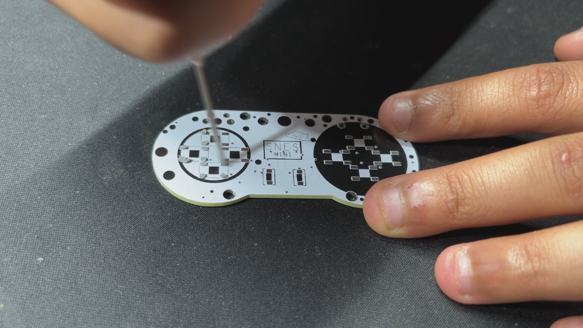
We begin the PCB Assembly process by placing SMD switches on the top layer of the PCB. This is carried out by applying solder paste to each component pad one by one with a solder paste dispensing needle, in this case using normal Sn/PB 63/37 Solder paste.
We use an ESD Tweezer to pick and install all SMD tactile switches.
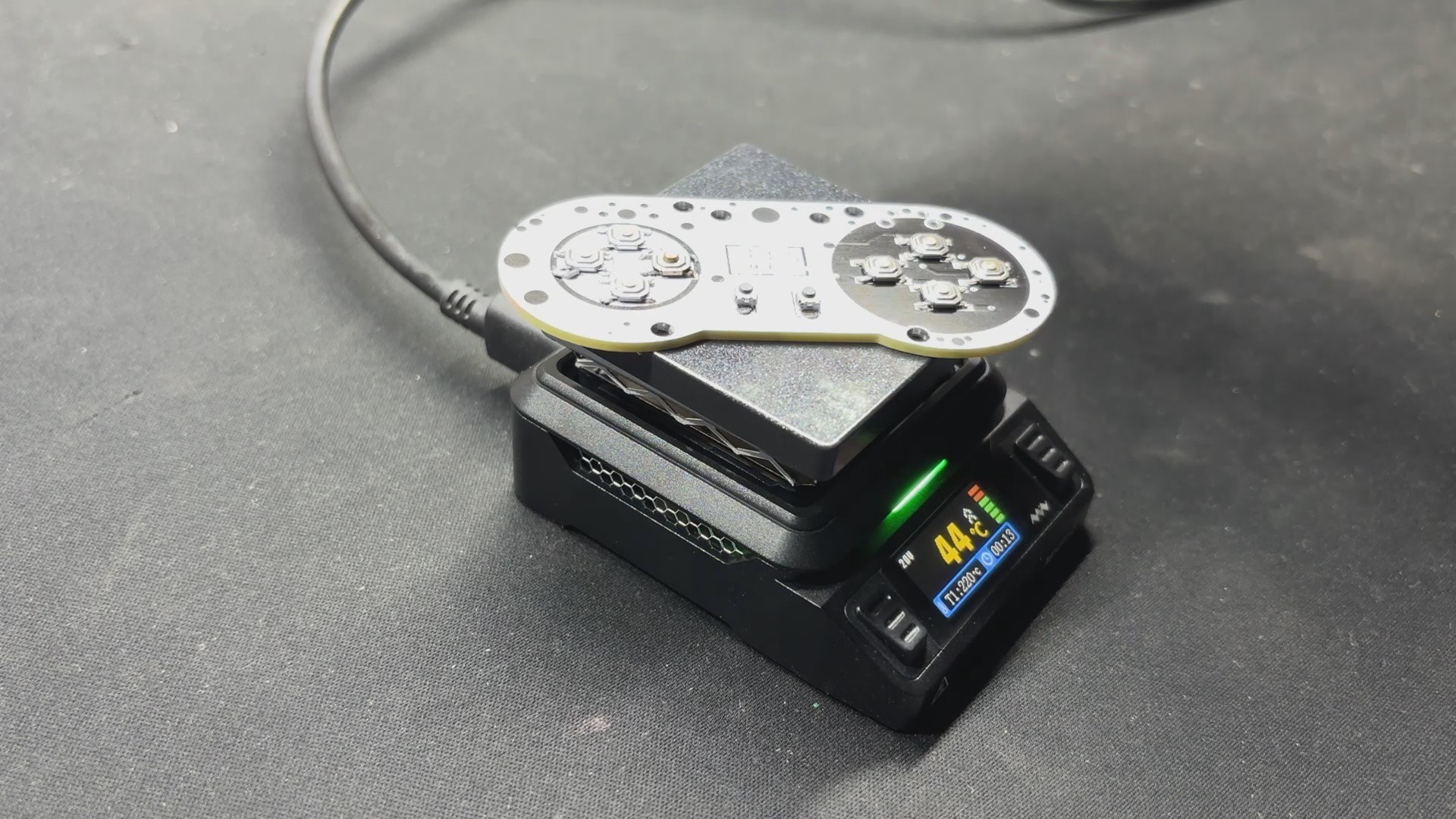
We next pick up the circuit and place it on our Miniware Reflow hotplate, which heats the PCB from below up to the solder paste melting temperature, allowing us to solder all of the components in their proper locations.
2
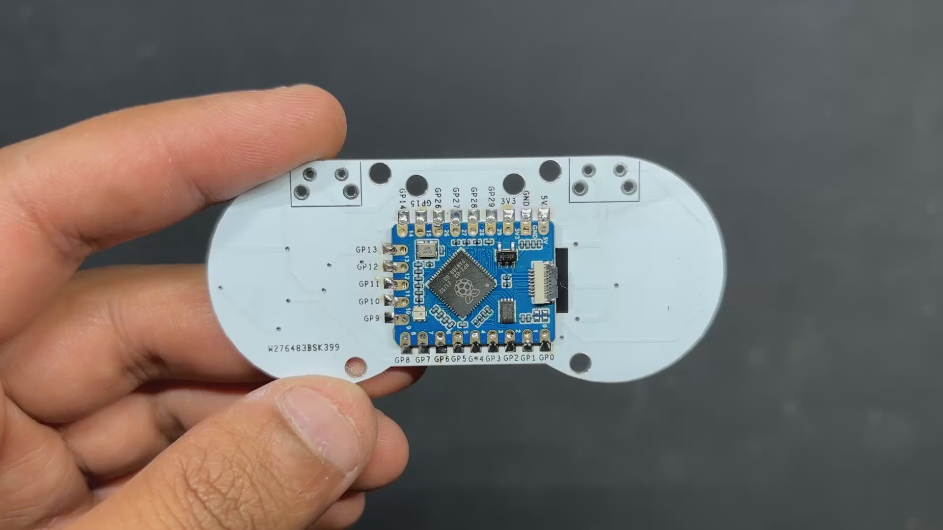
PCB ASSEMBLY—RP2040 Tiny Assembly
The RP2040 Tiny Assembly process differs slightly from the previous reflow process in that we cannot use a hotplate to heat the surface of the PCB since it contains SMD components on the top side, preventing us from using a hotplate to solder components on the bottom.
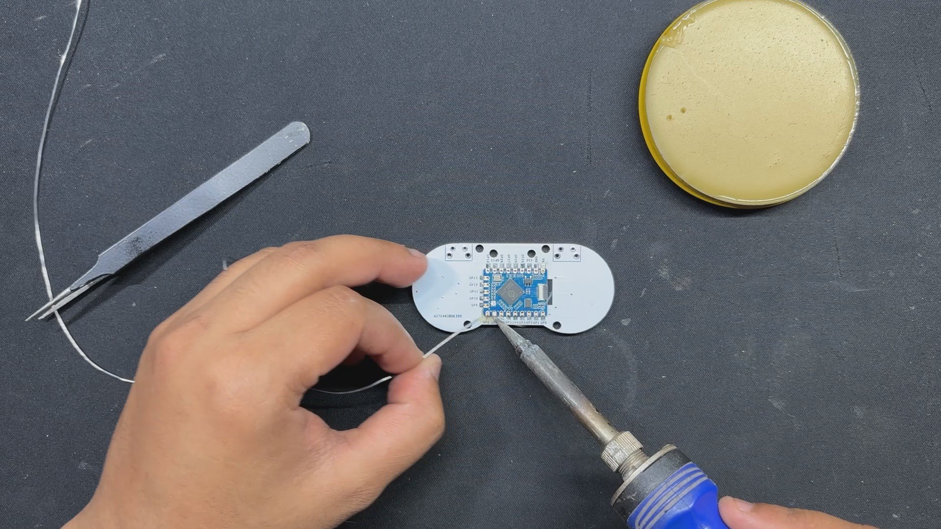
We use our soldering iron here; first, we dip the solder wire in flux before melting it on the first pad on the RP2040 tiny's footprint.
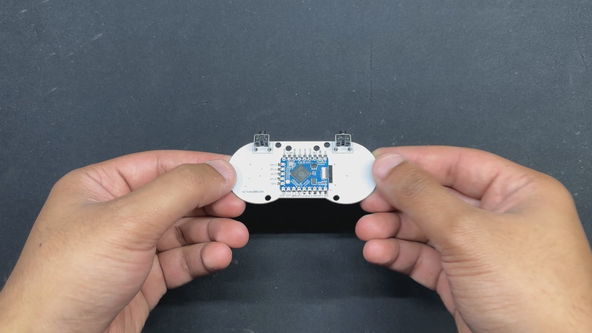
We use tweezers to pick and place the RP2040 in its location, then use a soldering iron to heat up the previously soldered pad. This will melt the solder and attach the RP2040 to its footprint.
We then solder the opposing terminals of the RP2040 Tiny, securing the module with its PCB Footprint. All that remains is to solder all pads with a soldering iron.
3
PCB ASSEMBLY—THT Switch Assembly
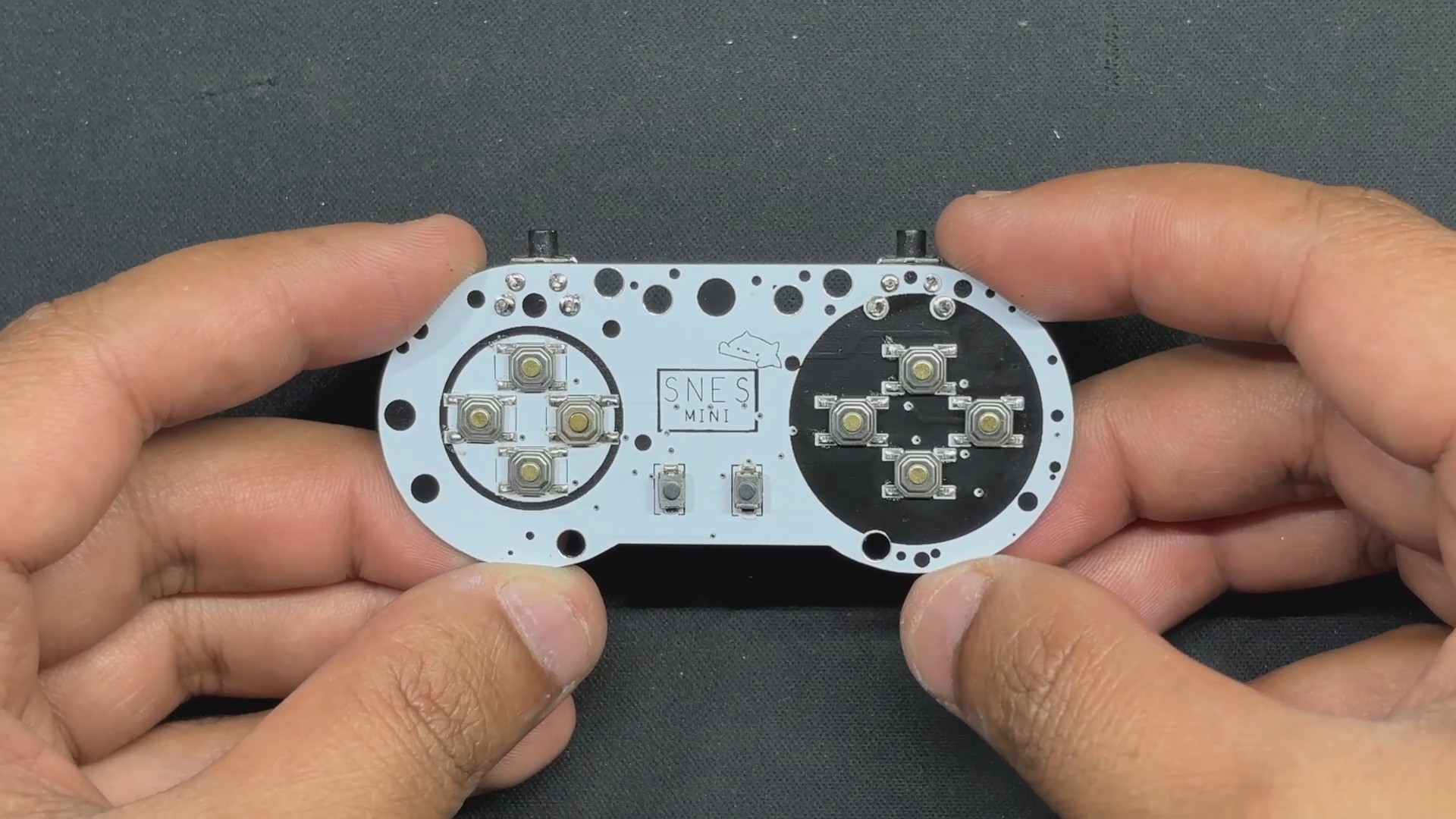
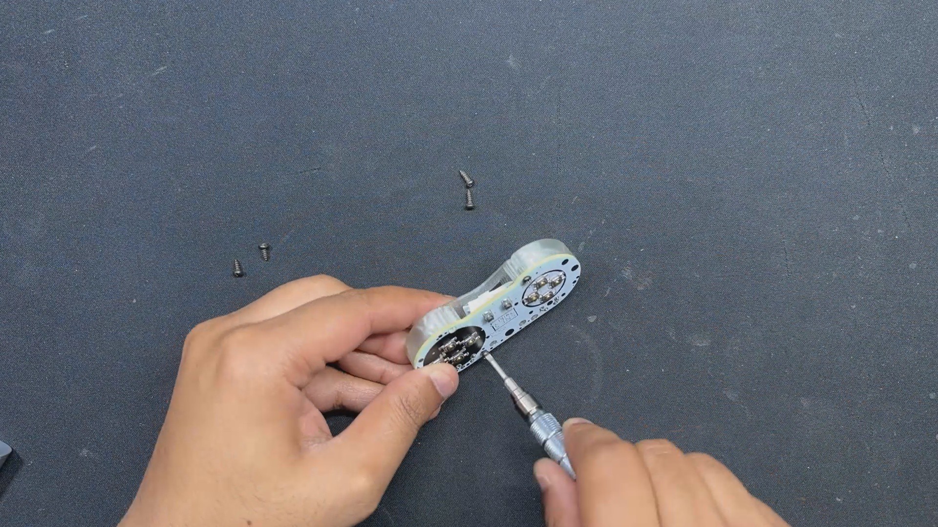
We install the THT switches from the bottom side of the circuit.
next we solder their pads from the top side of the board with a soldering iron.
Finally, we use a wire cutter to trim the THT Vertical Switch Pads that are visible from the top side.
4
Adapter Board & Controller Connection
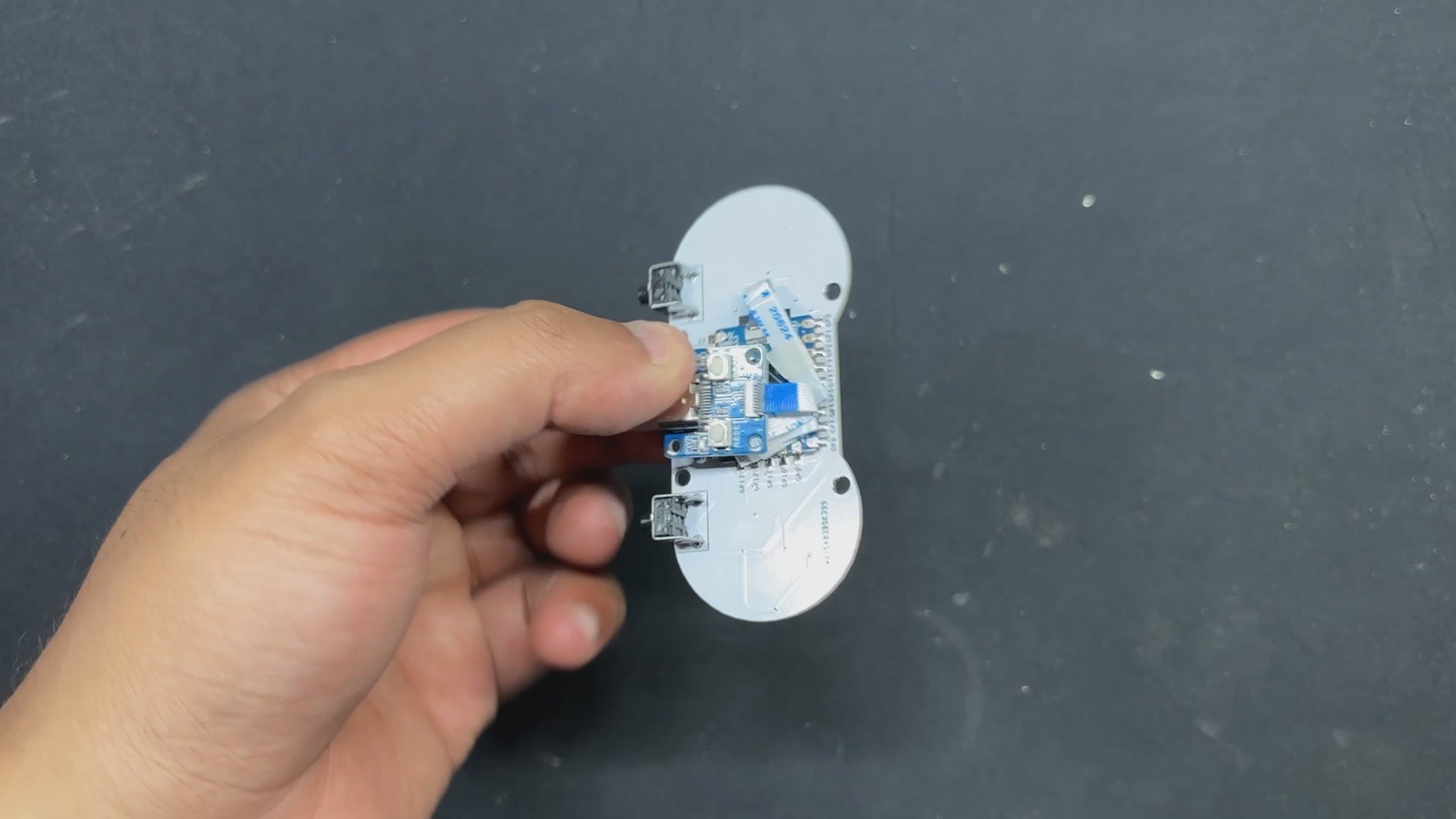
Now that the board assembly is complete, we begin the assembly process of connecting the USB Adapter Board to our Main Switch Board. For this link, we utilize the provided Flexible cable, which we first attach to the Type C board.
Next, we connected the flex cable to the connector found on the RP2040 Tiny board. The connection order of the flex cable is crucial; the blue side should likewise be on the top side, and the cable should be routed all the way through the inner connector.
Also, the cable that came with the RP2040 was rather long, so we bent it to make it shorter.
5
FRAME ASSEMBLY
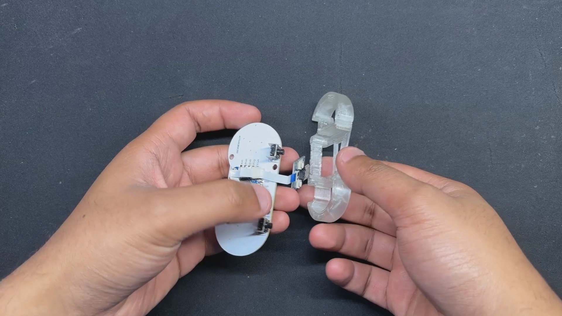
The frame assembly process begins with passing the USB Adapter board through the Frame part, followed by aligning the circuit's mounting holes with the Frame part's.
We then use four M2 screws to secure the frame part to the circuit.
Next, place the adaptor board over the screw bosses added to the back side of the frame and fasten it in place with two M2 screws.
The Pocket SNES Assembly has been completed; let us take a look at the code for this project.
6
CODE
This was the code used in this project and it's a simple one.
for (int i = 0; i < NUM_BUTTONS; i++) { if (digitalRead(buttonPins[i]) == LOW) { report[i / 8] |= (1 << (i % 8)); anyPressed = true; } }
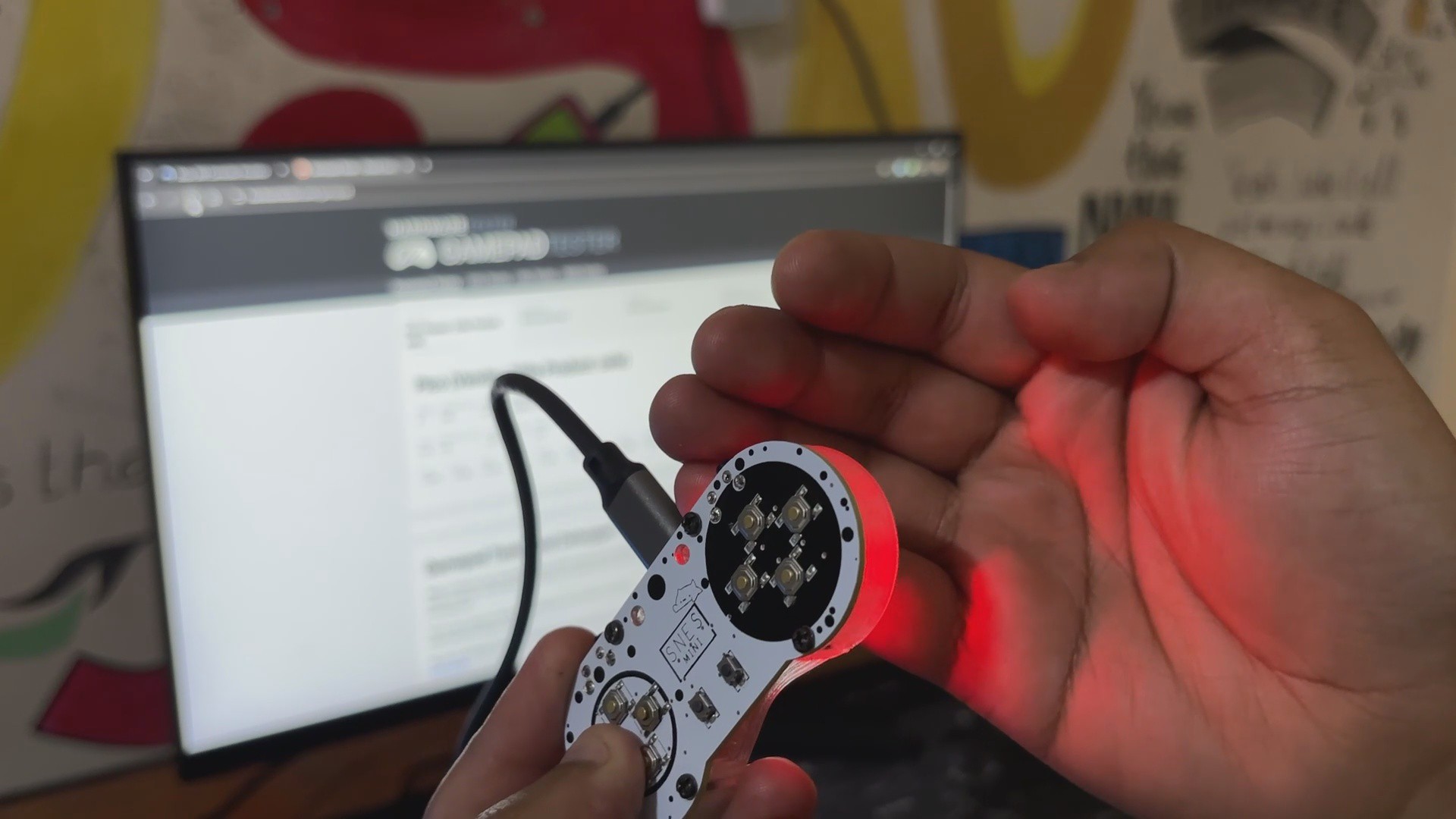
// Update LED: Purple if any button is pressed if (anyPressed) { pixel.setPixelColor(0, pixel.Color(255, 0, 255)); // Purple } else { pixel.setPixelColor(0, 0); // Off } pixel.show();
usb_hid.sendReport(0, report, sizeof(report)); }
7
RESULT
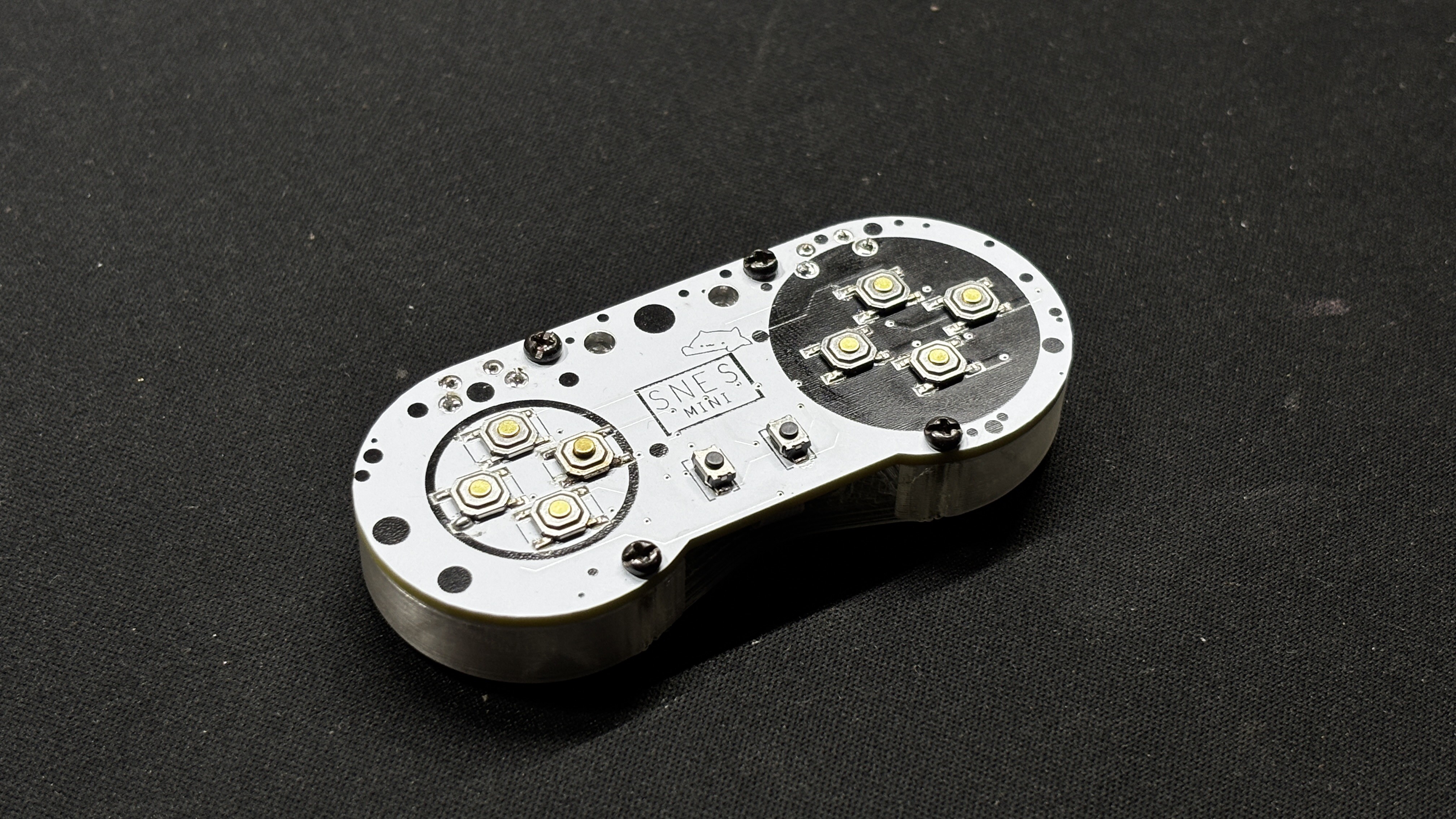
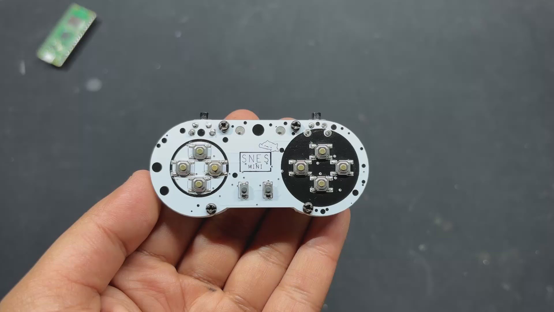
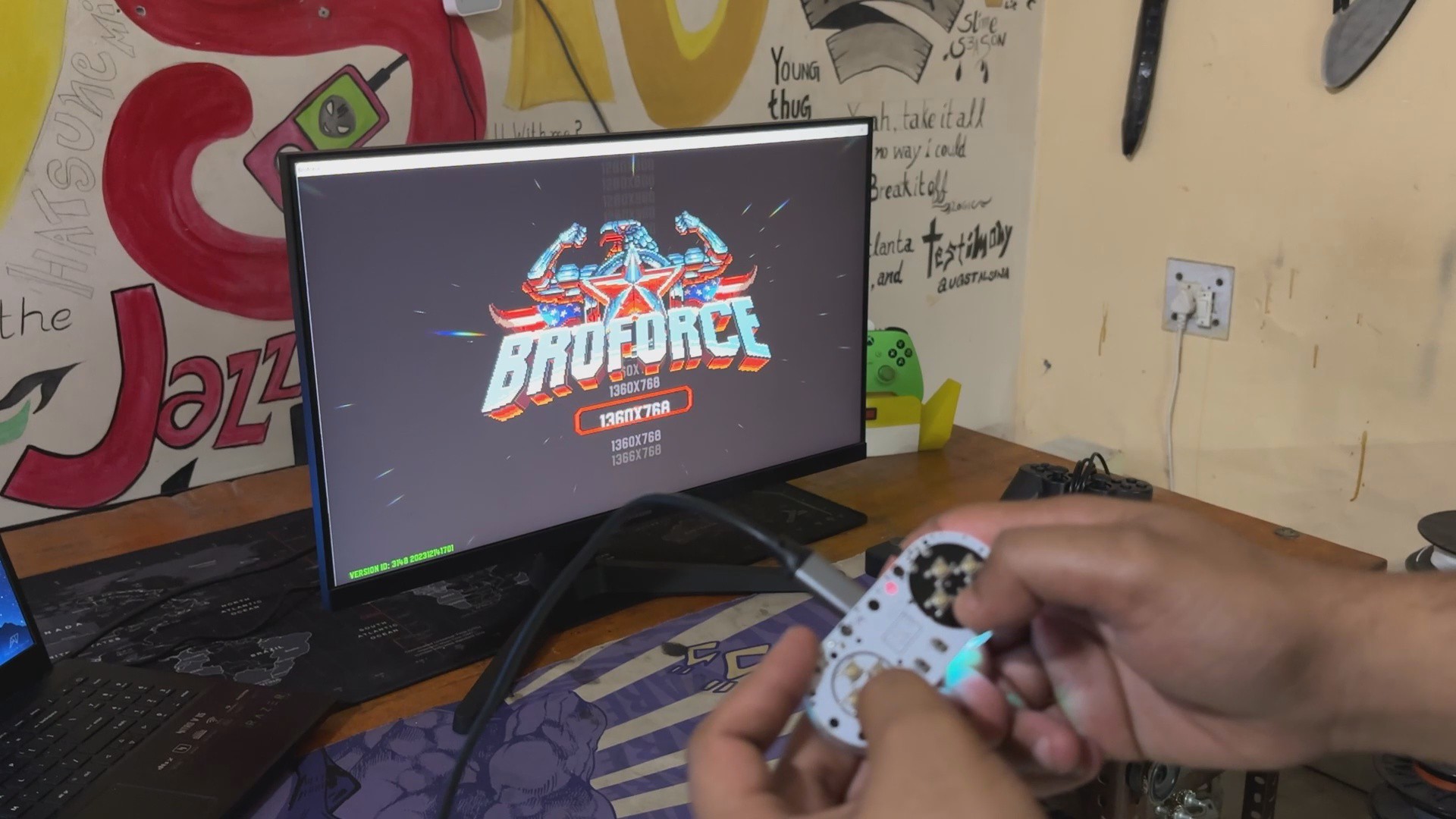
Here's the end result of this simple and tiny build: the Pocket SNES game Controller, an extremely portable gaming controller designed for playing old retro games with a layout similar to the SNES. It can also be used to run select modern titles that don't require left and right thumbsticks.
This device has dimensions of 74.5mm x 33.8mm x 11.5mm, making it one of the tiniest DIY game controllers.
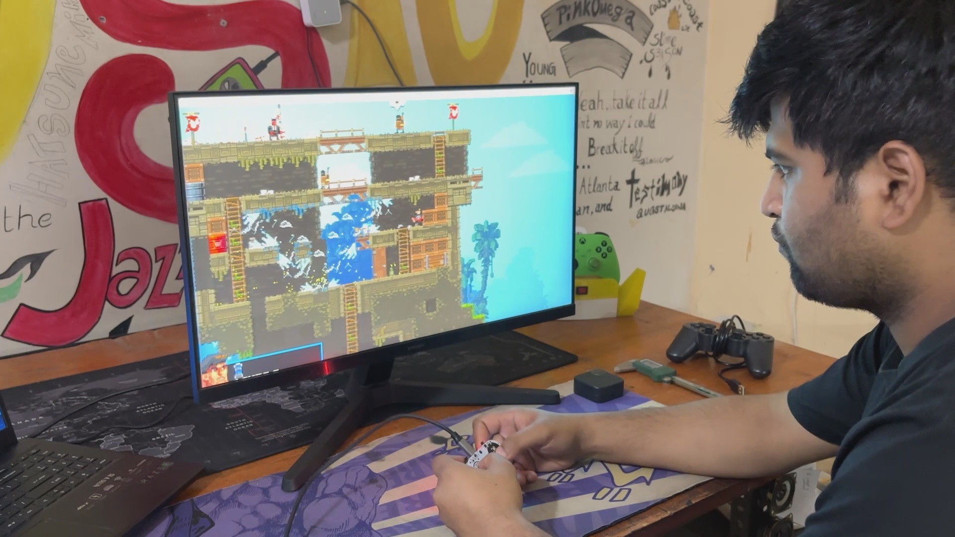
For testing, we first played Broforce, an action-packed, side-scrolling run 'n' gun game with a campaign, bonus levels, unlocked characters, and violent enemy clashes. Broforce is a group of hyper-masculine action heroes inspired by renowned characters from old movies and TV shows. They fight terrorists and free their fellow Brothers from captivity. Each Bro has distinct talents, weaponry, and special attacks, making them handy in a variety of circumstances. This game is pretty awesome and fun to play in multiplayer.
The controller is an ideal match for a side-scrolling game; the controls were first mapped in the game settings, allowing us to manage our player.
We installed Broforce on Windows, but what if we want to utilize this controller on another operating system, such as Raspberry Pi or another game emulation OS? Testing was critical since it would allow us to use this controller with our past Raspberry Pi-based game console projects.
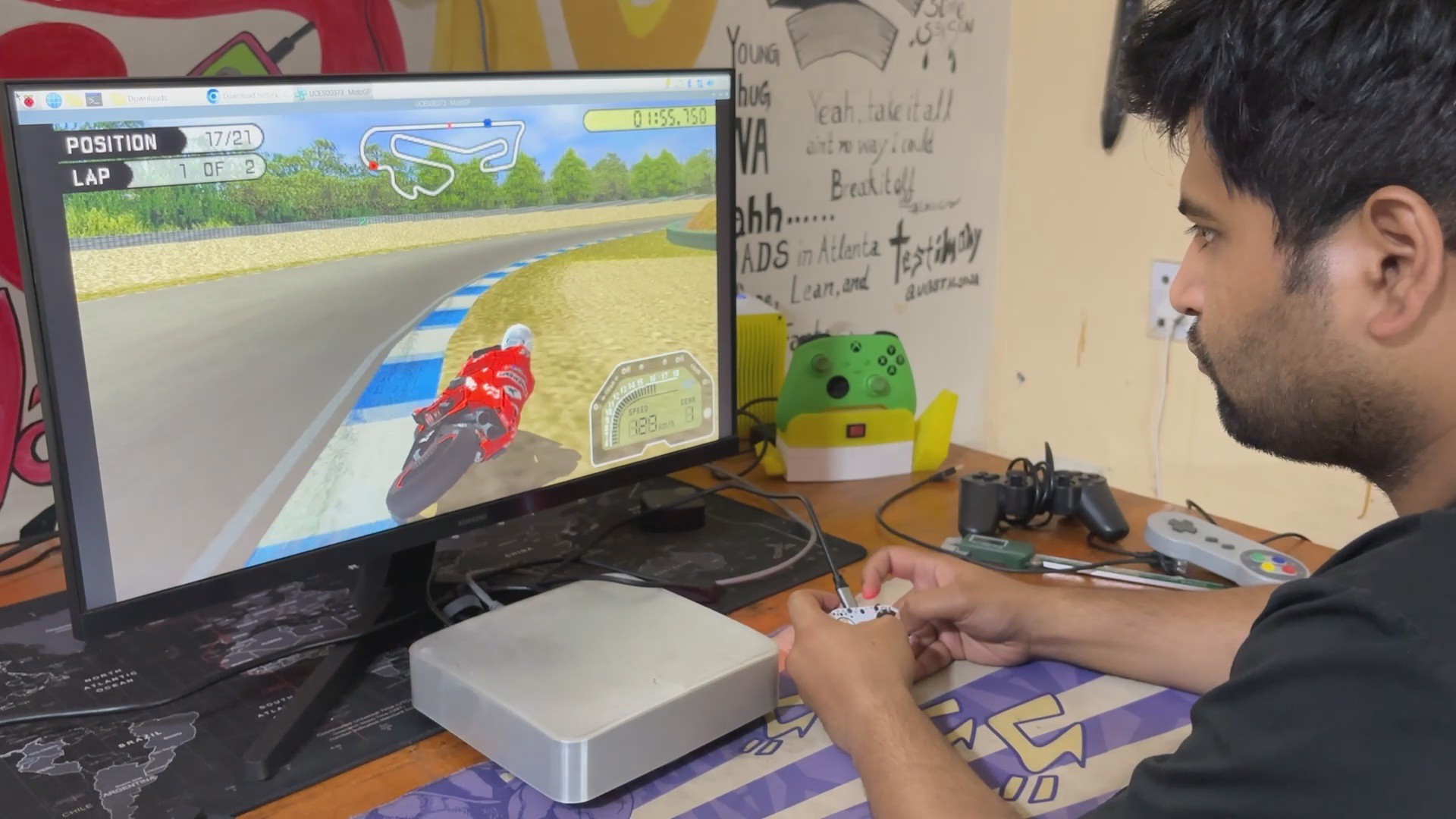
Using our previous build MAC Pi, we installed the PPSSPP emulator using Pi applications and then played a few PSP games, including Dead or Alive Paradise and Moto GP 3. We first had to map the button in the settings, and then both games ran quite smoothly with our Mini Controller.
The Small SMD Buttons were not particularly soft to use, but they functioned properly overall.
8
WHAT'S NEXT
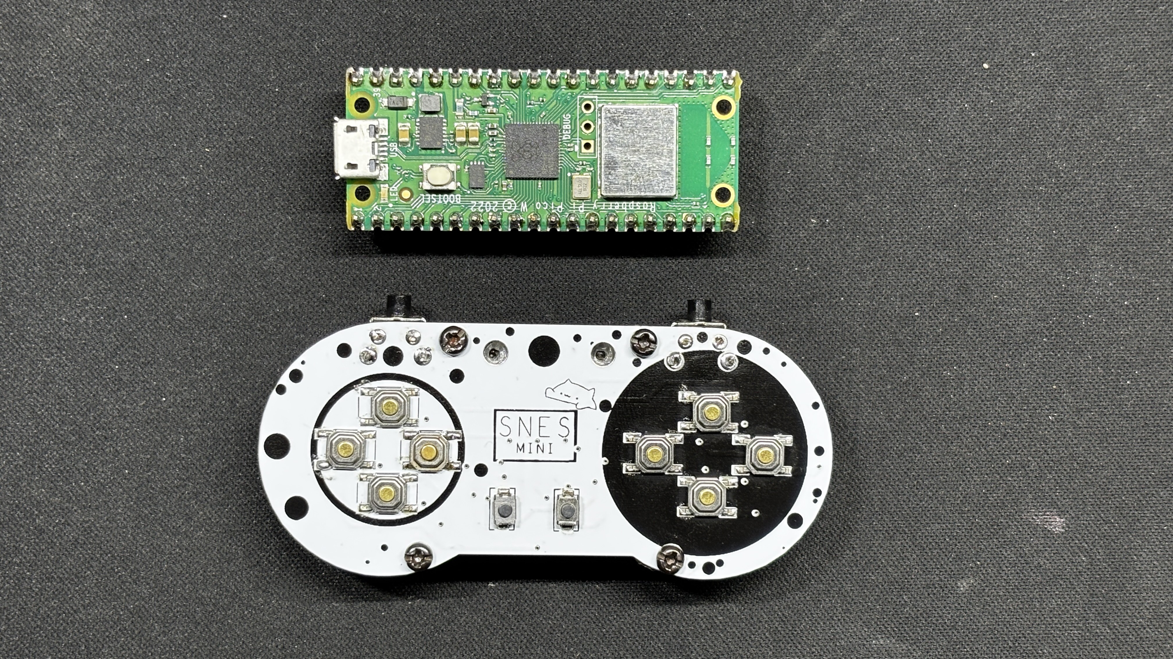
The one thing I'd like to change in the next version is to replace the RP2040 Tiny with the Raspberry Pi PICO W or 2W, due to the WiFi/Bluetooth connectivity, which eliminates the need for a USB cable entirely. This will allow the device to be truly portable.
For the time being, this project has been completed, and all of the necessary details, including PCB files, code, and other information, are all attached.
 Arnov Sharma


Discussions
Become a Hackaday.io Member
Create an account to leave a comment. Already have an account? Log In.