 Tabet
TabetThere is a list of components you need to get a 4.8khz sine wave:
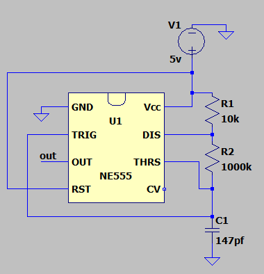
1 NE555
1 Capacitor 47pf
1 Capacitor 100pf
3 Capacitors 10nf
1 Capacitor 100nf
1 Resistor 1MΩ
1 Resistor 10KΩ
3 Resistors 3.3kΩ
First, start the assembly of the NE555 in astable mode.
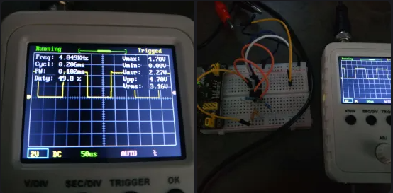
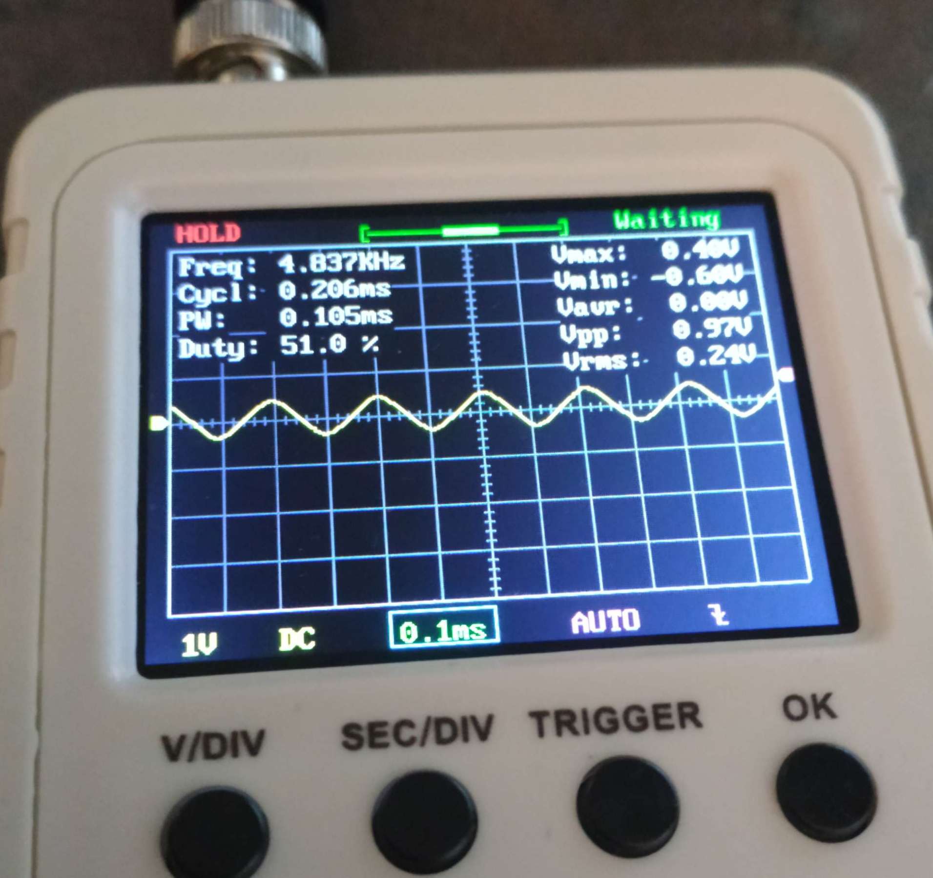
Then mesuring the signal from the Pin 3 (out), we get a square wave of 4.85khz
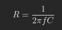
Using the formula :
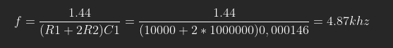
nota: to keep a duty cycle of 50%, R2 has to be 100 times R1.
Now let's check it in real life.
To get a sine wave we have to build a 3 Stages Low Pass RC Filter.
For that we use this formula:
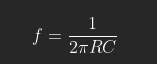
We know the frequency so let's detemine R and C.
Since i don't have that many capacitors i choose C = 10nf.
So we have to find R.
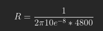
We end up with R = 3.3KΩ
Building the 3 stages Low Pass RC Filter.
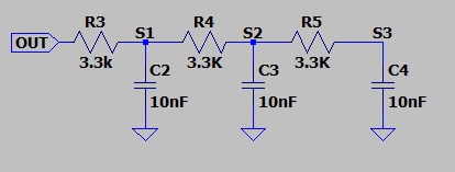
Why a 3 stages filter ?
Each stage serve to eliminate the harmonics and then get a sine wave.
Let's probe at S1 S2 and S3.
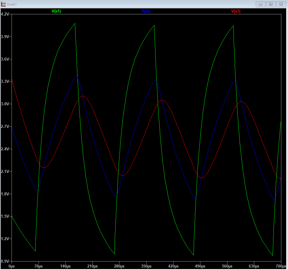
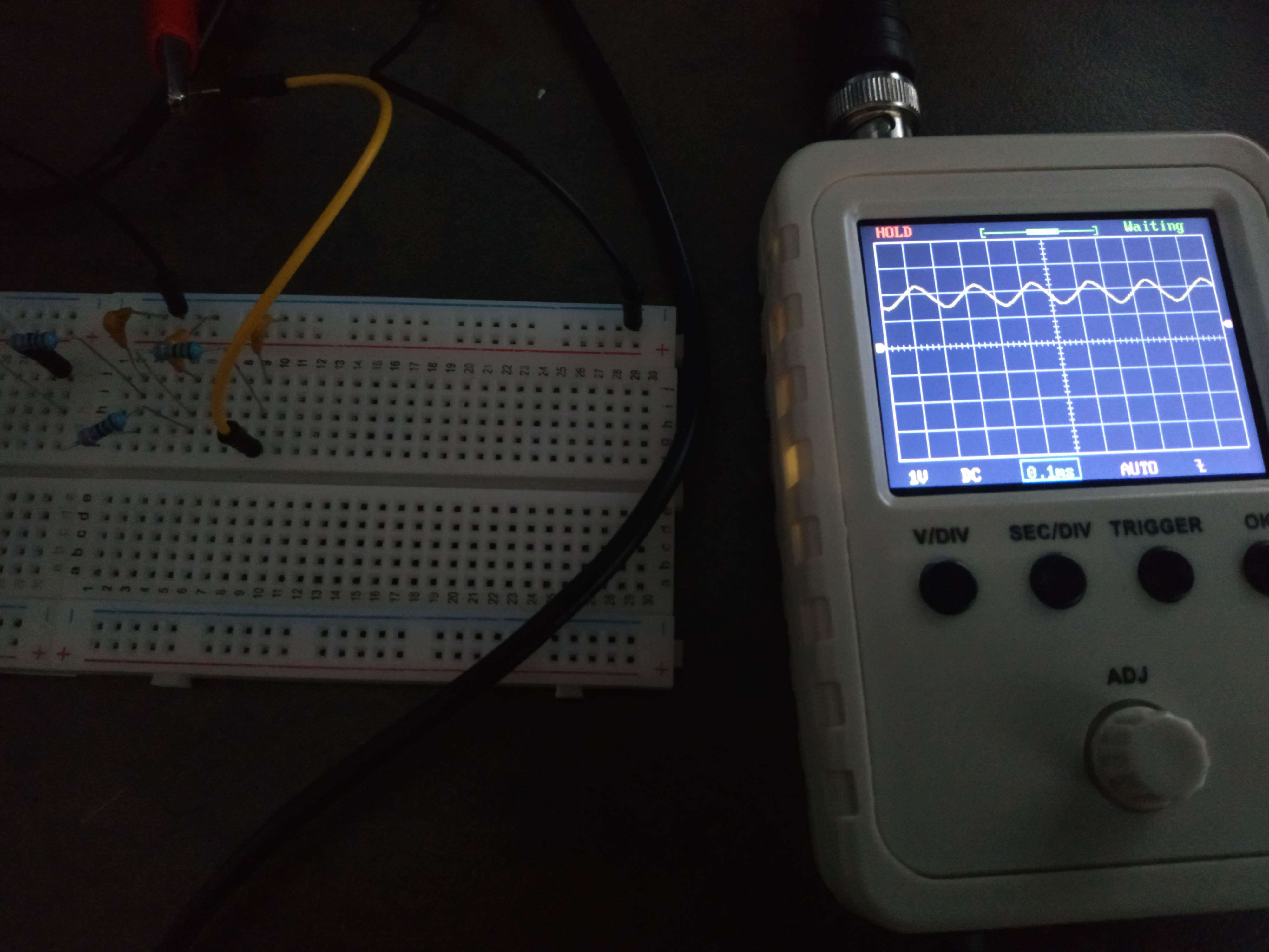
There is an issue it has a DC component that is "crushing" our sine wave after filtering.
So to block the DC we add a 100nf capacitor in serie with the filter just at the ouput of the pin3(out) of the NE555.
And so we have the NE555 timer used as sine wave generator.
I hope you've learned something funny !

 Ringo2k
 Mark Omo
 Dan Berard
 Nitesh Kadyan
Ok, this is a nice demonstration of how to put theory into practice. But you can get off-the-shelf function generation from an XR2206 chip which has been around for a long time. Not just sine, but also square and triangle waveforms, from 1 Hz to 1 MHz. There are lots of kits based on this chip.