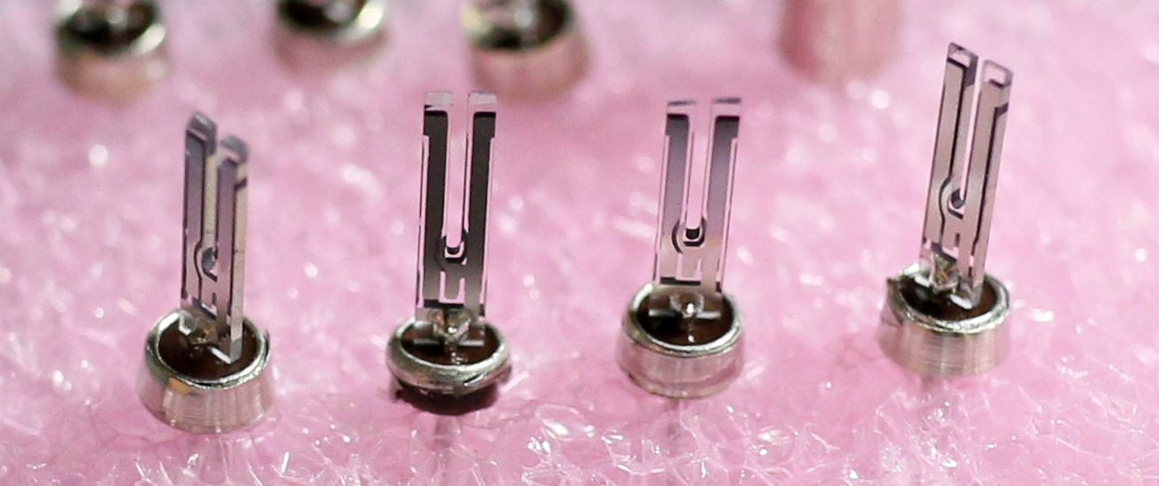
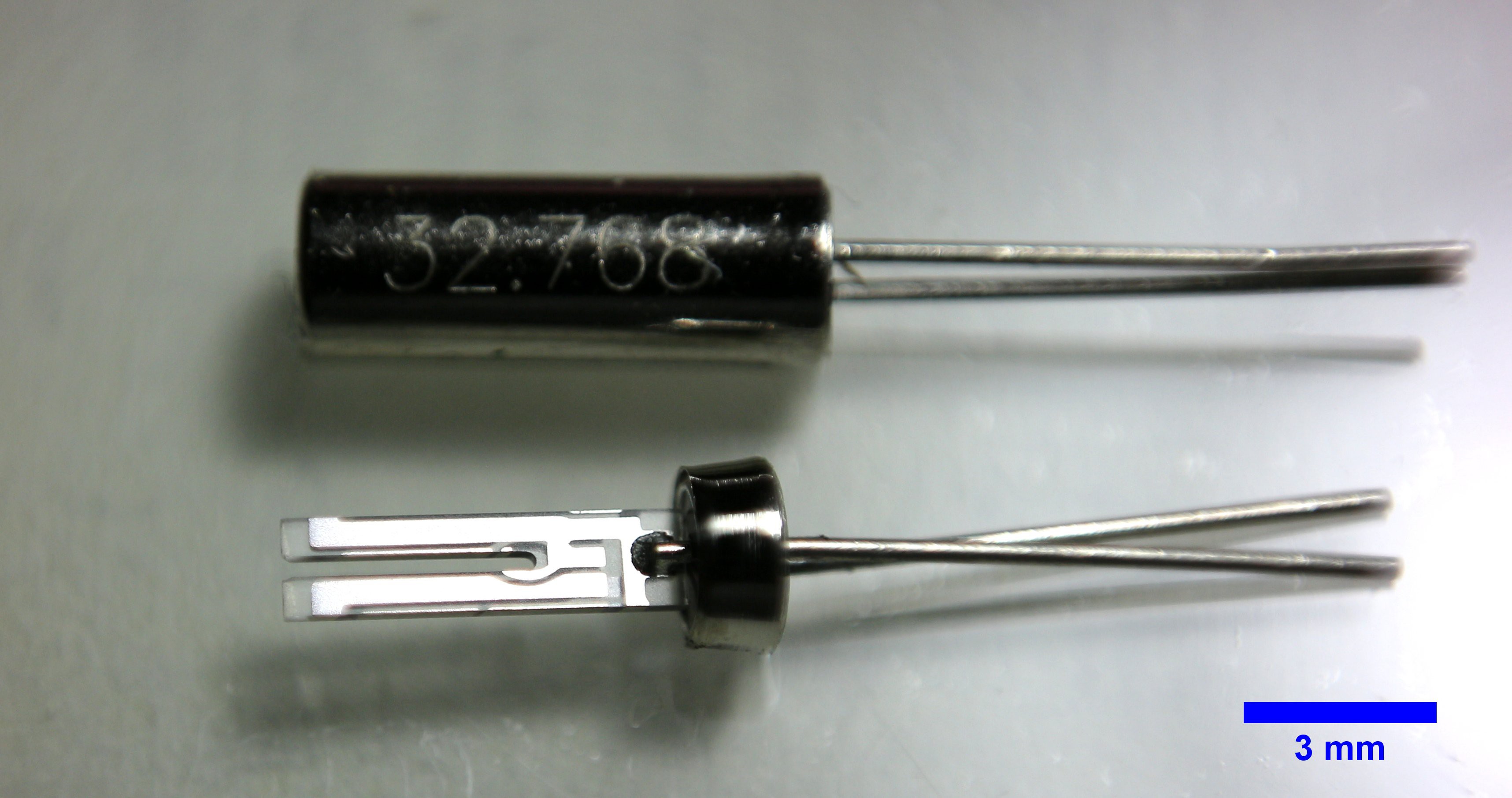
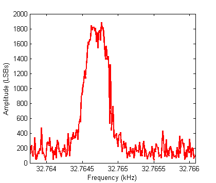
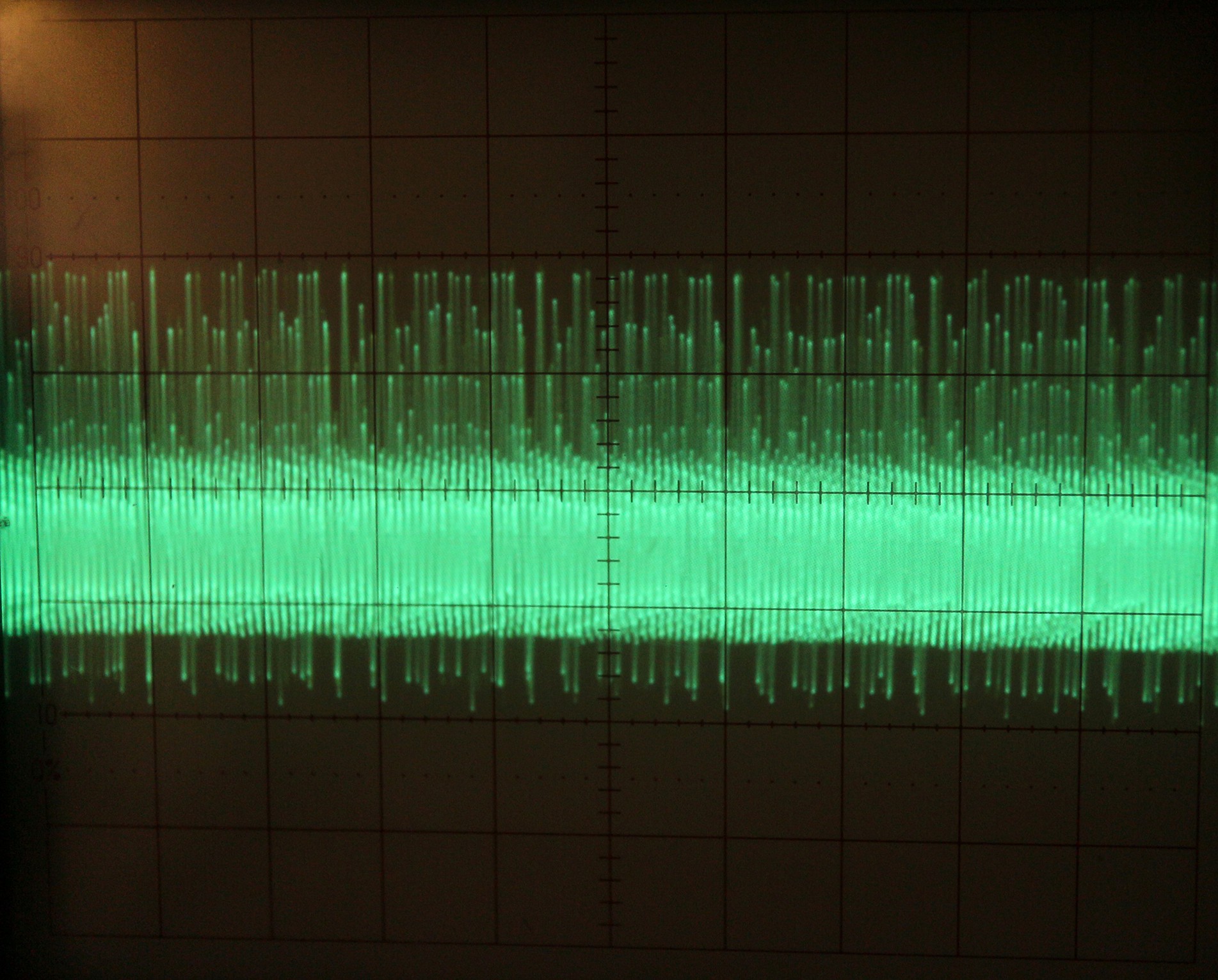
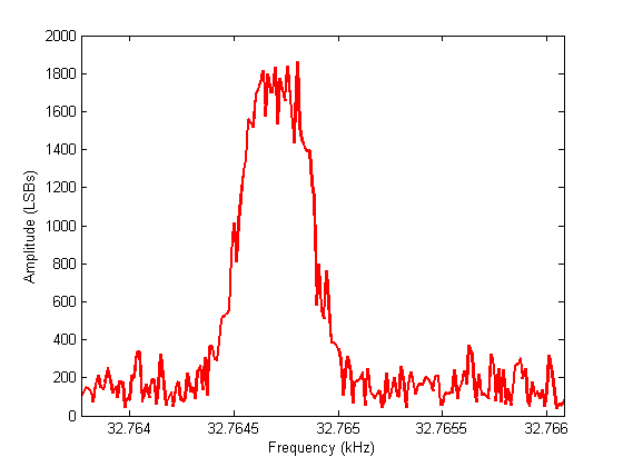
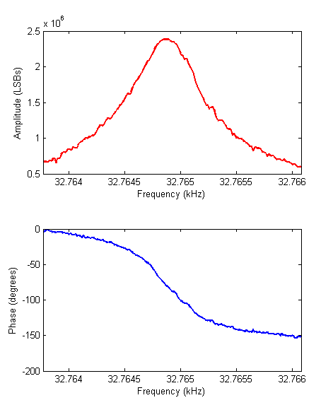
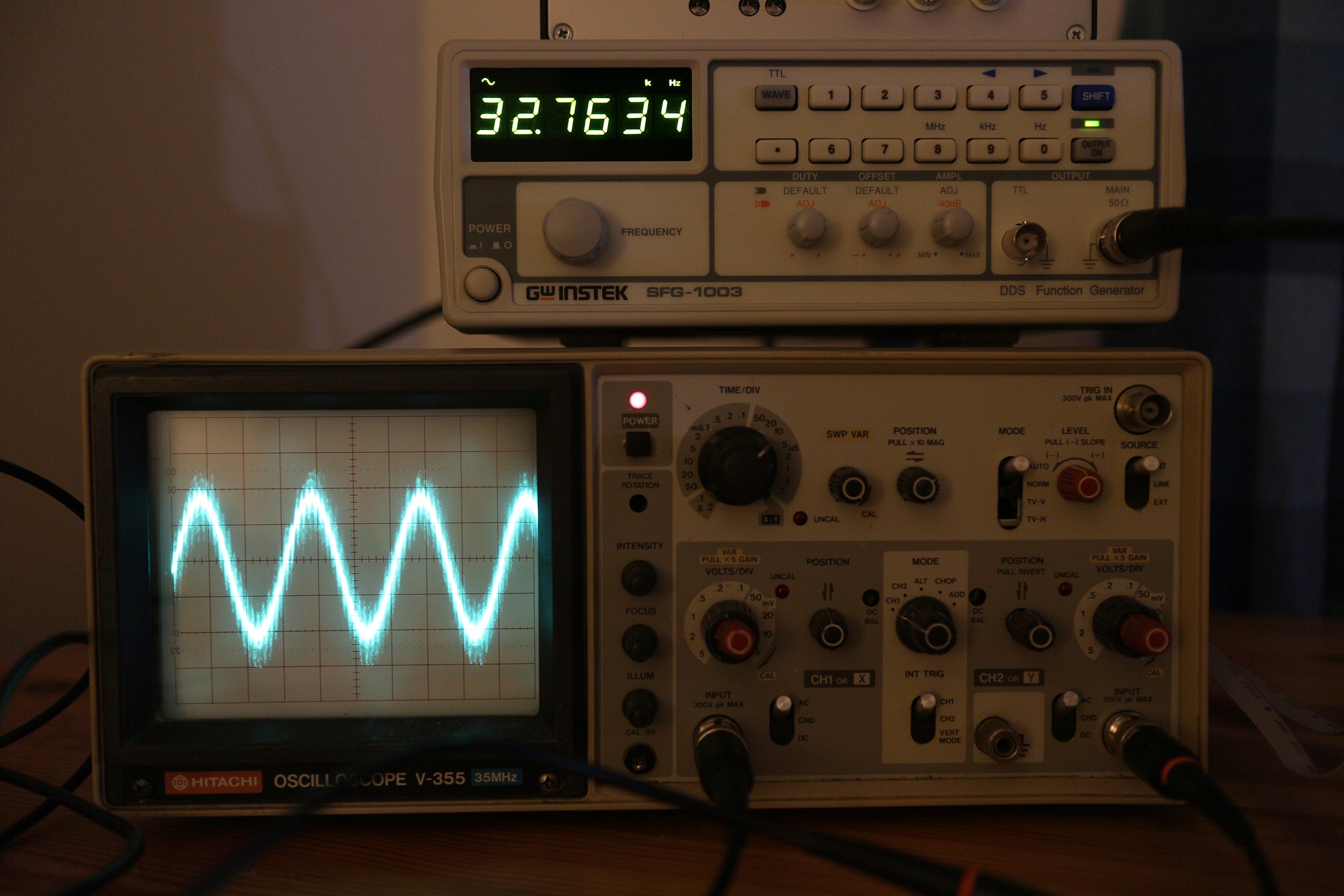
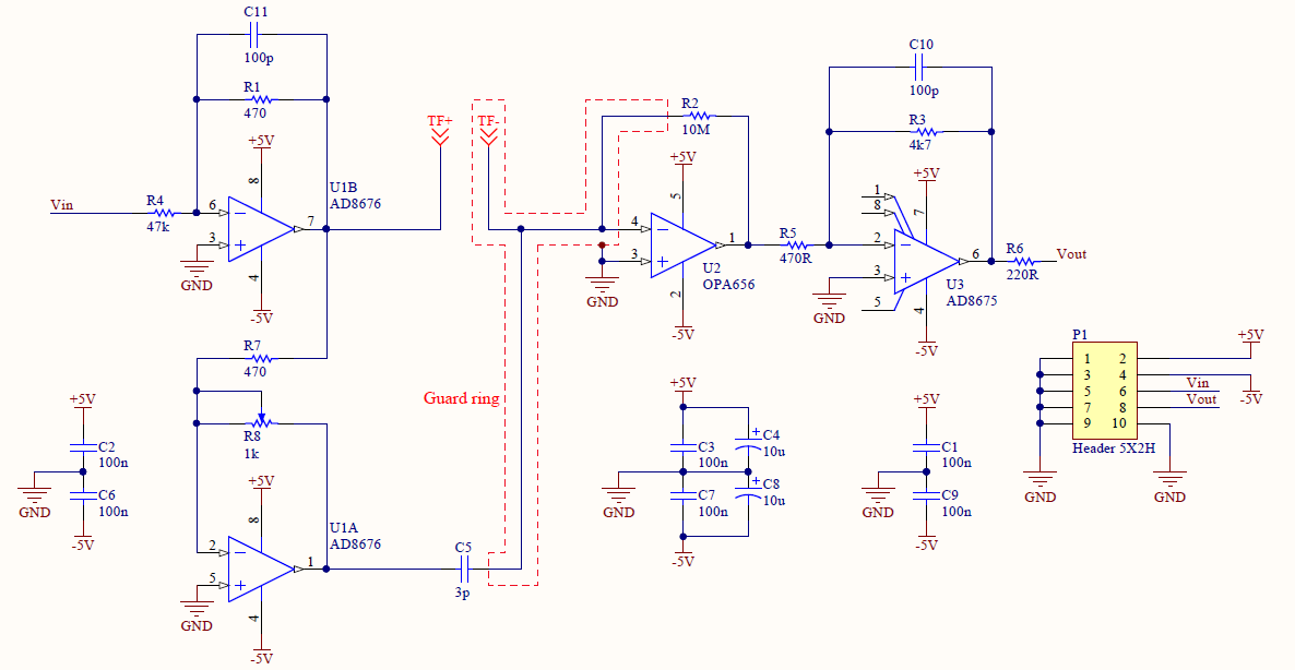
The excitation signal source will be a DDS sine wave generator, implemented in an FPGA. The piezoelectric response of the tuning fork is measured by an I-V converter (as in STM) and digitized. A lock-in amplifier, also implemented in the FPGA, extracts the amplitude and phase of the signal. The phase signal is fed to a PI loop which controls the DDS frequency. The amplitude is kept constant. The phase setpoint is 90 degrees to ensure that the tuning fork is driven at resonance, but the resonant frequency is allowed to change through tip-sample interactions.
This mode of operation is called frequency modulation. Amplitude modulation, in which the tuning fork is driven at a constant frequency and changes in amplitude are recorded, is simpler to implement but is slower due to the low frequency and high Q-factor of the quartz tuning fork. My controller will be able to operate in both modes.
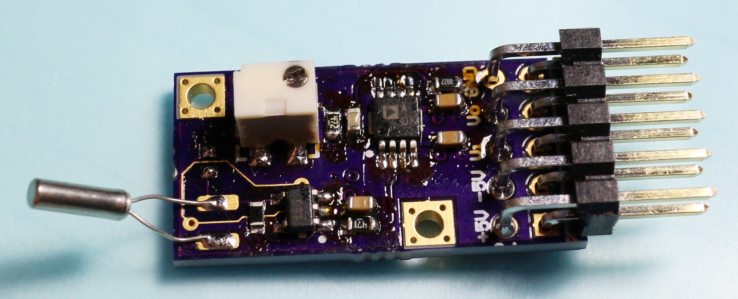
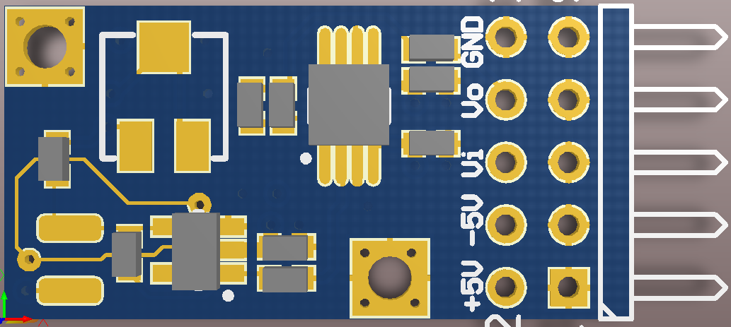
So far I've built the preamplifier and have a basic lock-in detector and numerically-controlled oscillator running on an FPGA.
The preamplifier PCB is available on OSH Park.
 Dan Berard
 Ted Yapo
 gitmodimo
 Andrew Ferguson
Since you already have the STM have you thought about electric field induced deposition for the tip on the fork? You could use the fork as the sample and bring a wolfram wire on top of it and put a negative bias on the wolfram tip. In theory you should be able to deposit wolfram atoms very narrowly on the fork and thereby create a new tip.