Dan Berard
-
Quartz tuning fork decapping
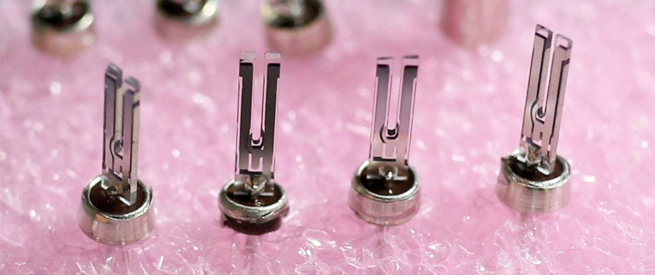
08/29/2016 at 04:37 • 0 commentsRemoving the steel can from quartz tuning forks turned out to be a bit tricky, and I broke about half of the ones I bought. Luckily these things cost only $0.22CAD in 10X quantity, so breaking a few is no big deal.
Chucking the can in a drill and filing the edge while spinning it worked alright, but using a lathe was quicker and easier. I tried at first mounting the base of the can in a drill chuck (on the lathe) so that the fork would remain in the chuck when the can was cut off, but found I couldn't get enough grip on it this way. Holding it in a collet rather than a drill chuck would provide better grip, but I don't have a collet adapter for my lathe. Mounting the top of the can in the chuck gives good grip, but means that the fork falls out once the can is cut off, so the lathe needs to be running at low speed! The forks are very fragile and can easily break from hitting the side of the can once it's cut off.
![]()
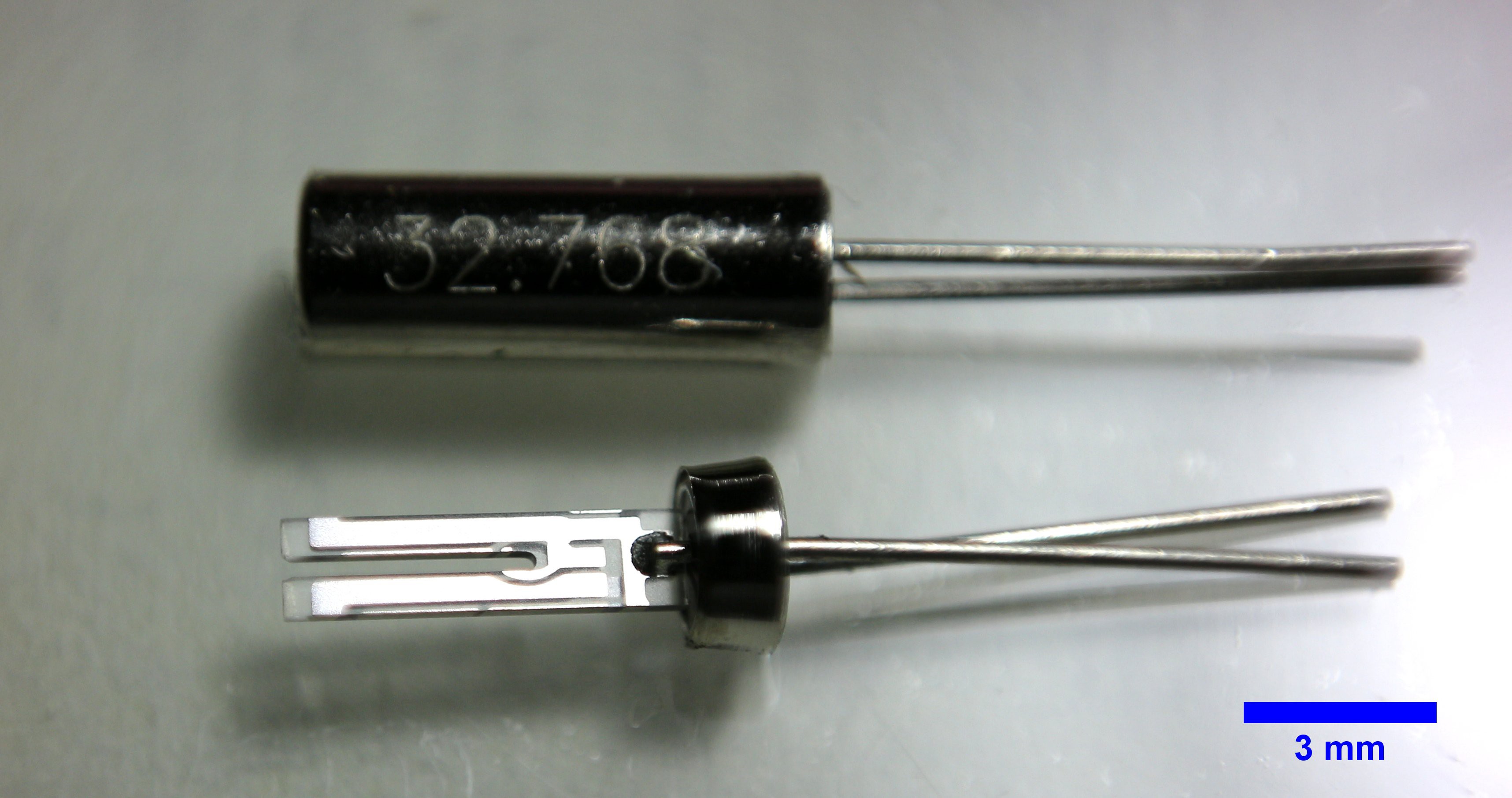
Quartz tuning forks are available in different sizes. The one shown below is ~6 mm long with 4 mm long prongs (digikey link: https://www.digikey.ca/product-detail/en/abracon-llc/AB38T-32.768KHZ/535-9034-ND/675229). Smaller ones are available, but I'd rather start with something easier to handle.
![]()
The next step step is to glue one prong to a rigid support. Super-gluing to a small piece of glass cut from a microscope slide turned out to be relatively easy. For the sensing tip, I've been attempting to glue a short piece of 50 um tungsten wire to the other prong. This is the real tricky part! The added mass of the glue will reduce the resonant frequency and Q, and should be minimized. CA type glues don't seem to be suitable for this, so I'm experimenting with epoxies. Positioning and holding the tiny piece of wire in place while the tiny blob of epoxy cures is not trivial! A pair of fine, self-closing tweezers might be good for this.
-
Lock-in measurements
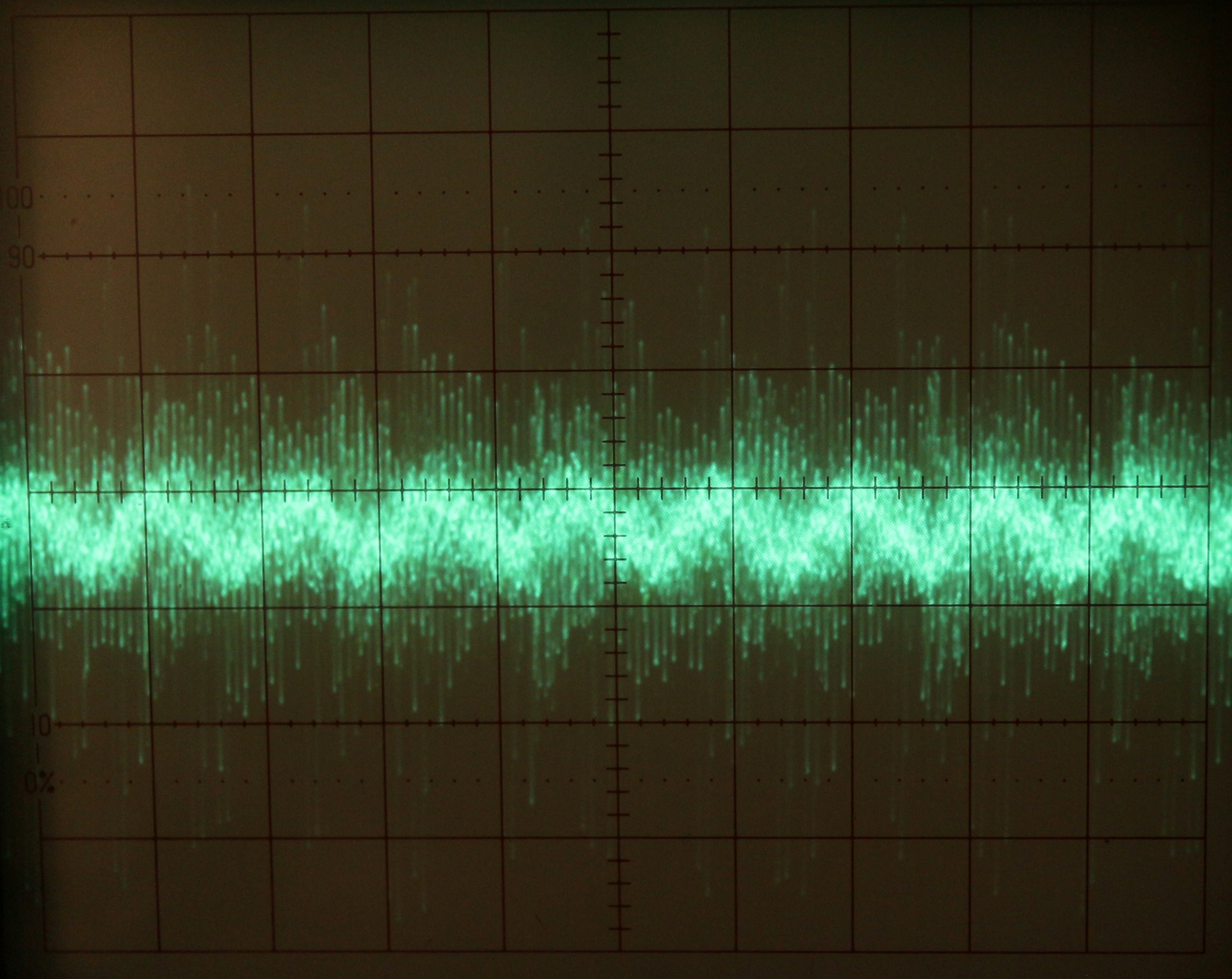
07/30/2015 at 02:48 • 0 commentsI thought it would be interesting to see if I could measure oscillations of the tuning fork without applying any drive signal. Sure enough, a small, noisy signal (noise from SPMS) from the preamplifier output is visible on the scope at 100 mV/div vertical scale and 20 us/div timescale:
![]()
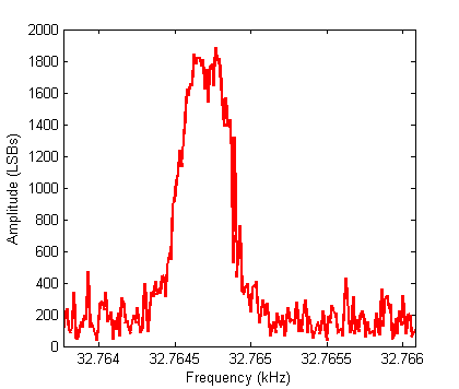
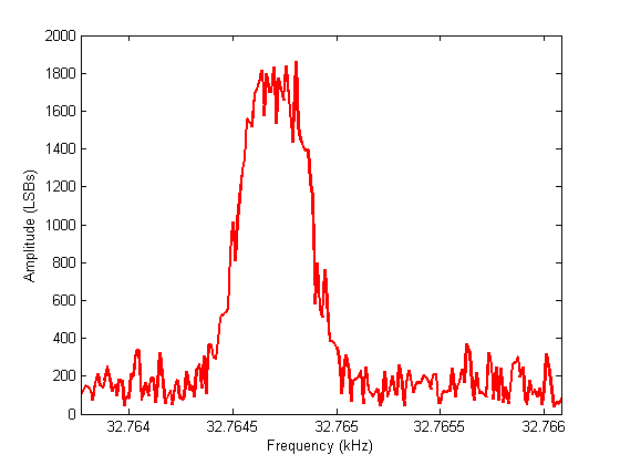
The tuning fork oscillates at it's resonant frequency despite there being no drive voltage. This could be induced thermally, electrically by conducted or radiated noise, or acoustically by a nearby air-conditioner. The small oscillation signal is easily measured by the FPGA lock-in detector despite the high noise. Here's the result of a narrow frequency sweep:
![]()
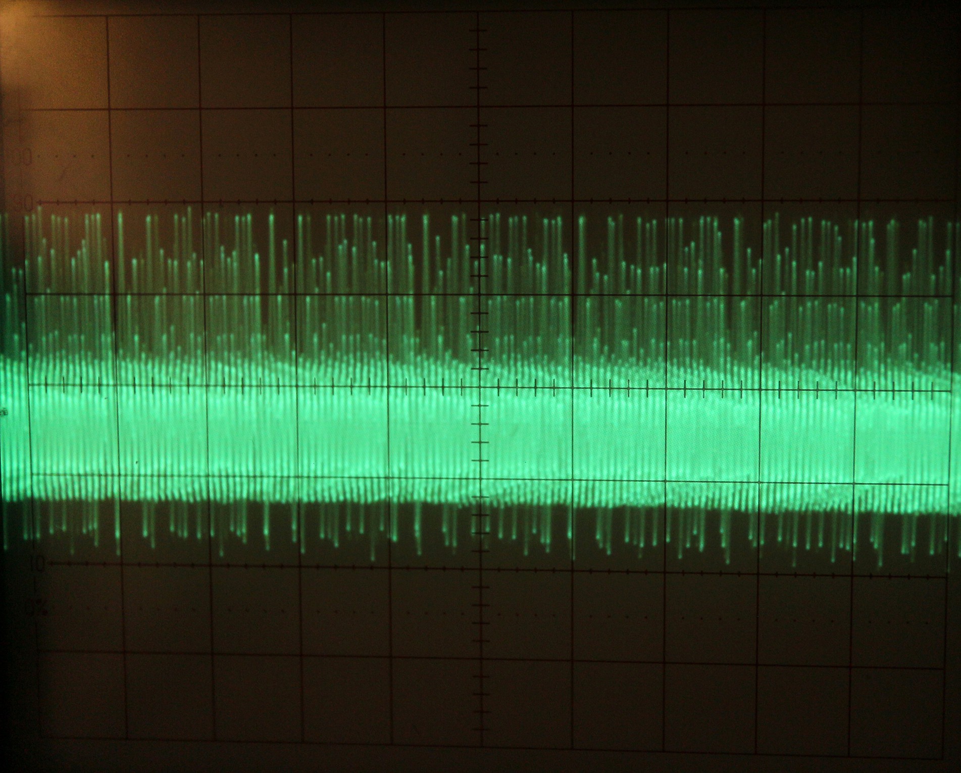
Not bad. I then placed an SMPS power brick next to the preamp, burying the signal in switching noise. The peak-peak noise is ~40X larger than the signal. This scope trace is at 1 V/div and 20 us/div:
![]()
The resulting amplitude curve is essentially unchanged, since the signal and noise are at different frequencies. The lock-in measures only the signal in a very narrow band around the frequency of interest. Pretty cool!
![]()
-
Measuring the resonant frequency and phase using an FPGA
07/28/2015 at 02:49 • 0 commentsI've got a numerically-controlled oscillator (NCO) and lock-in detector working on a DE-0 nano FPGA board, which I've now got hooked up to my preamplifier board. At the moment I'm using a sigma-delta DAC implemented in the FPGA (50 MHz PWM output on a GPIO pin) to generate the ~32.768 kHz excitation sine wave.
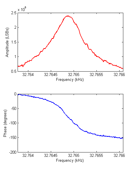
After finding the resonance of a tuning fork with a function generator and scope, I used a Nios II processor in the FPGA to sweep the frequency of the NCO over a narrow ~2.3 Hz range close to resonance, while reading the amplitude and phase outputs from the lock-in detector. Here are the results:
![]()
A bit noisy, possibly from the SMPS powering the preamplifier or the PWM DAC I used, but the resonance peak and phase shift are clearly defined. There is some offset in the phase introduced by the preamplifier. The reason I'm doing this frequency sweep is to zero in on the resonant frequency and find the phase at resonance, which in this case is not exactly -90 degrees (it's about -81 degrees) due to the offset error. Next step is to add a PI control loop between the lock-in and NCO, and use this resonant phase as the setpoint to the controller so that it always drives the sensor at resonance.
We can also calculate the Q-factor from the resonant frequency and width of the amplitude curve. Just looking at the amplitude graph, and using
gives a pretty large Q of about 40000. I expect it to decrease by an order of magnitude when I remove it from the metal can. Because this value is so high, the sweep, although very narrow, took about 30 seconds. The amplitude responds very slowly to changes in the drive frequency, but the frequency responds immediately.
-
Preamplifier up and running!
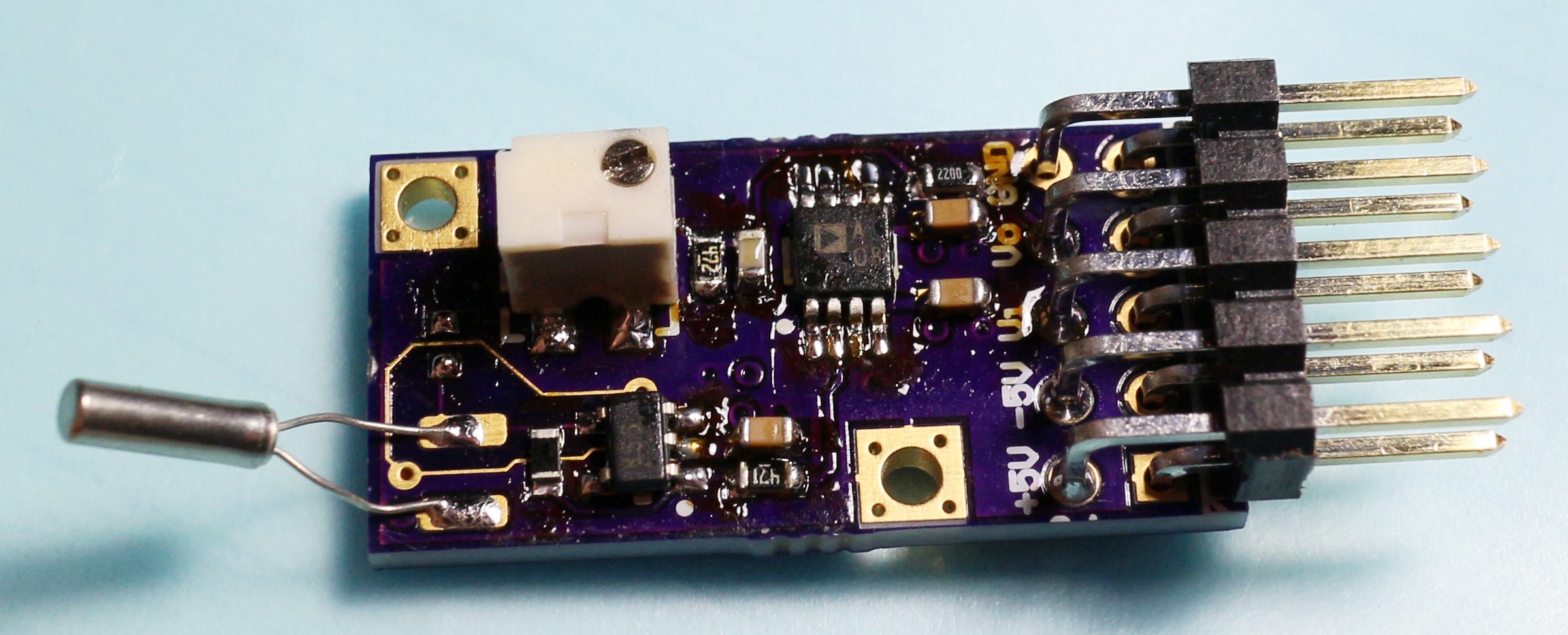
07/23/2015 at 02:49 • 0 commentsGot the preamplifier PCB in from OSHpark the other day and soldered it up.
![]()
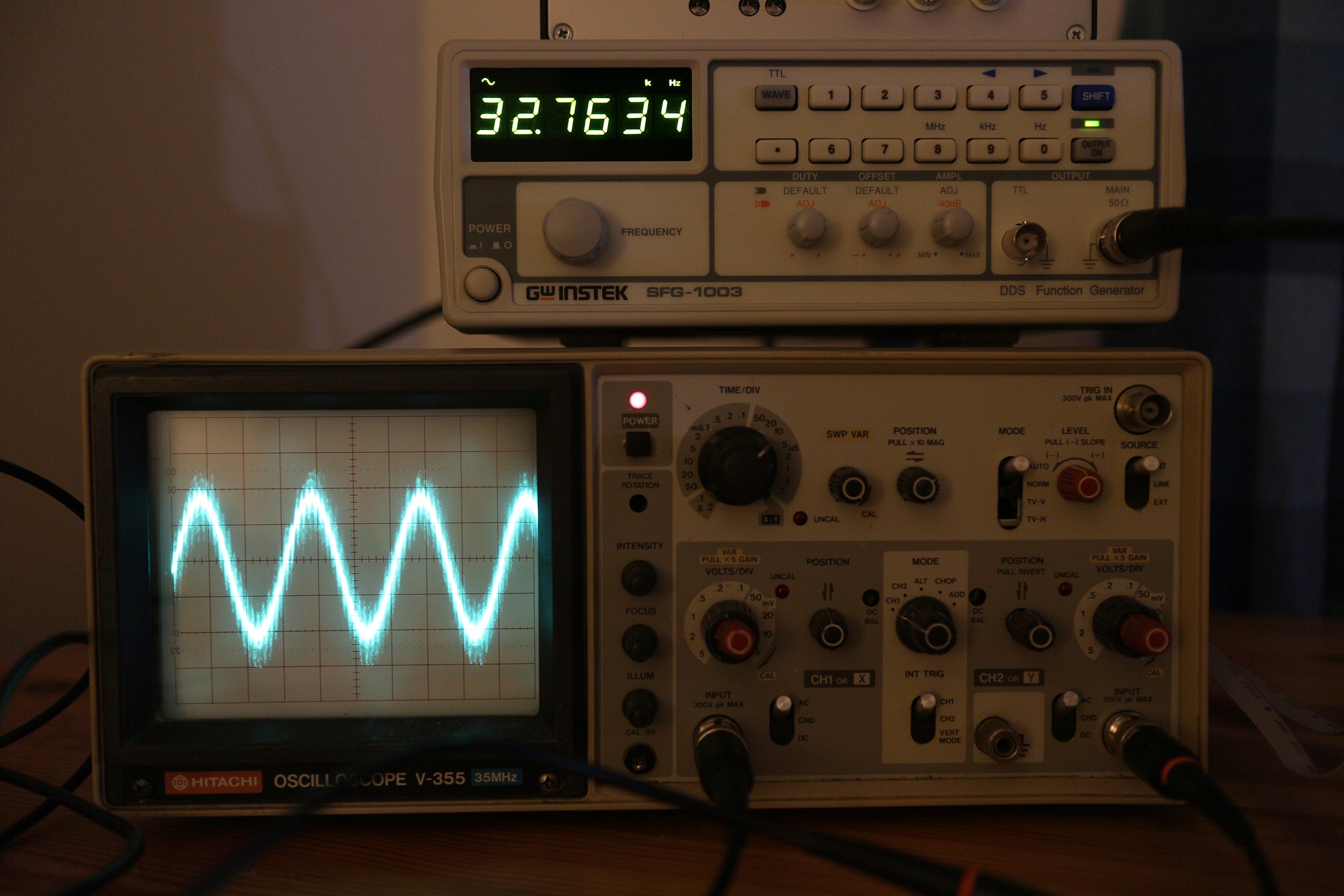
Hooked up a 32.768 kHz crystal and fed in a sine wave from a function generator. A few hundred mVpp is attenuated by a factor of 100 by the preamp to drive the crystal. Resonant frequency of this particular crystal is 32.7634 kHz. The waveform shown below is the preamp output of several Vpp. There's a ton of noise on it from the SMPS I'm currently using to power it. This will be replaced with a linear supply eventually.
![]()
The Q of these oscillators is quite high, but will decrease once removed from the metal can. The resonant frequency will also decrease by a few kHz when exposed to air. I was concerned about bandwidth with the 10M feedback resistor, but it turned out not to be a problem at all. Should be able to use 100 kHz or even 200 kHz tuning fork.
Here's the PCB on OSH Park: https://oshpark.com/shared_projects/eJGJCT8f
-
Preamplifier design
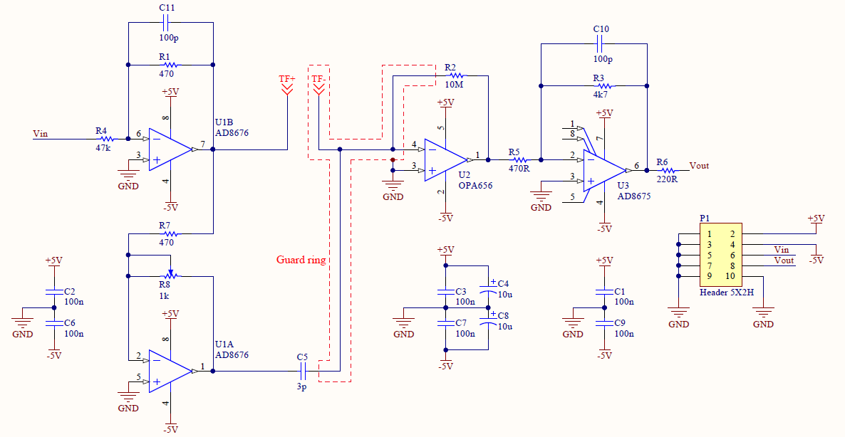
06/24/2015 at 04:06 • 1 commentThe preamplifier will be a small PCB mounted as close as possible to the tuning fork. It takes an input signal, which is divided by 100 by op-amp U1B and used to drive the tuning fork's oscillation, which should be around ~0.1 nm/mV. U2 is is a current-to-voltage converter used to measure the tuning fork's oscillation. The current should be in the nA range, at a frequency of ~25 kHz (but tuning forks are available up to 200 kHz, which would allow faster scanning), so I've used a high-speed, low-bias-current op-amp (OPA656) and routed a guard ring around the input node to keep leakage currents out. Getting a high enough bandwidth with a 10M feedback resistor requires that the parasitic capacitance across this resistor be less than 1 pF. U3 provides an additional gain of 10.
![]()
U1A inverts the excitation signal and drives a small capacitor, also connected to the I-V converter. By tuning the pot R8, the current can be adjusted to cancel out the current through the parasitic capacitance of the tuning fork electrodes and wiring. This way, the I-V converter only measures the piezoelectric response of the fork (which can be modeled as a series RLC circuit).
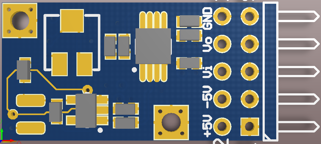
The PCB has 4 layers, and is 1" X 0.5". The two exposed pads at the bottom left are the connections for the tuning fork.
![]()
Here are some references I found useful. They really show that a tuning-fork oscillation controller can be built quite cheaply.
Frequency-Modulated Atomic Force Microscope
Quartz tuning fork-based FM-AFM