Introducing the String Controller, a wearable game controller that will transform the way we engage with games. Unlike traditional controllers, this unique approach allows players to operate the controller with their natural finger movements, providing a more ergonomic and simpler experience.
Details
Traditional game controllers need constant gripping, which can cause hand strain over time. But do we really need to hold them at all?
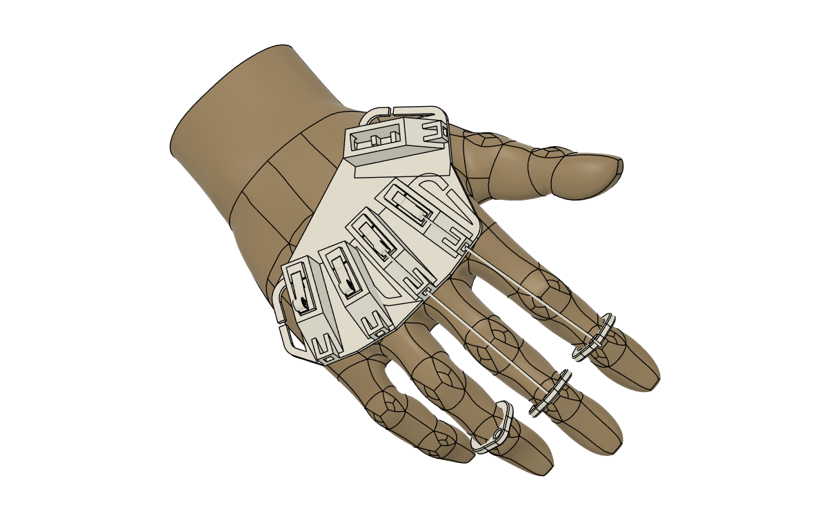
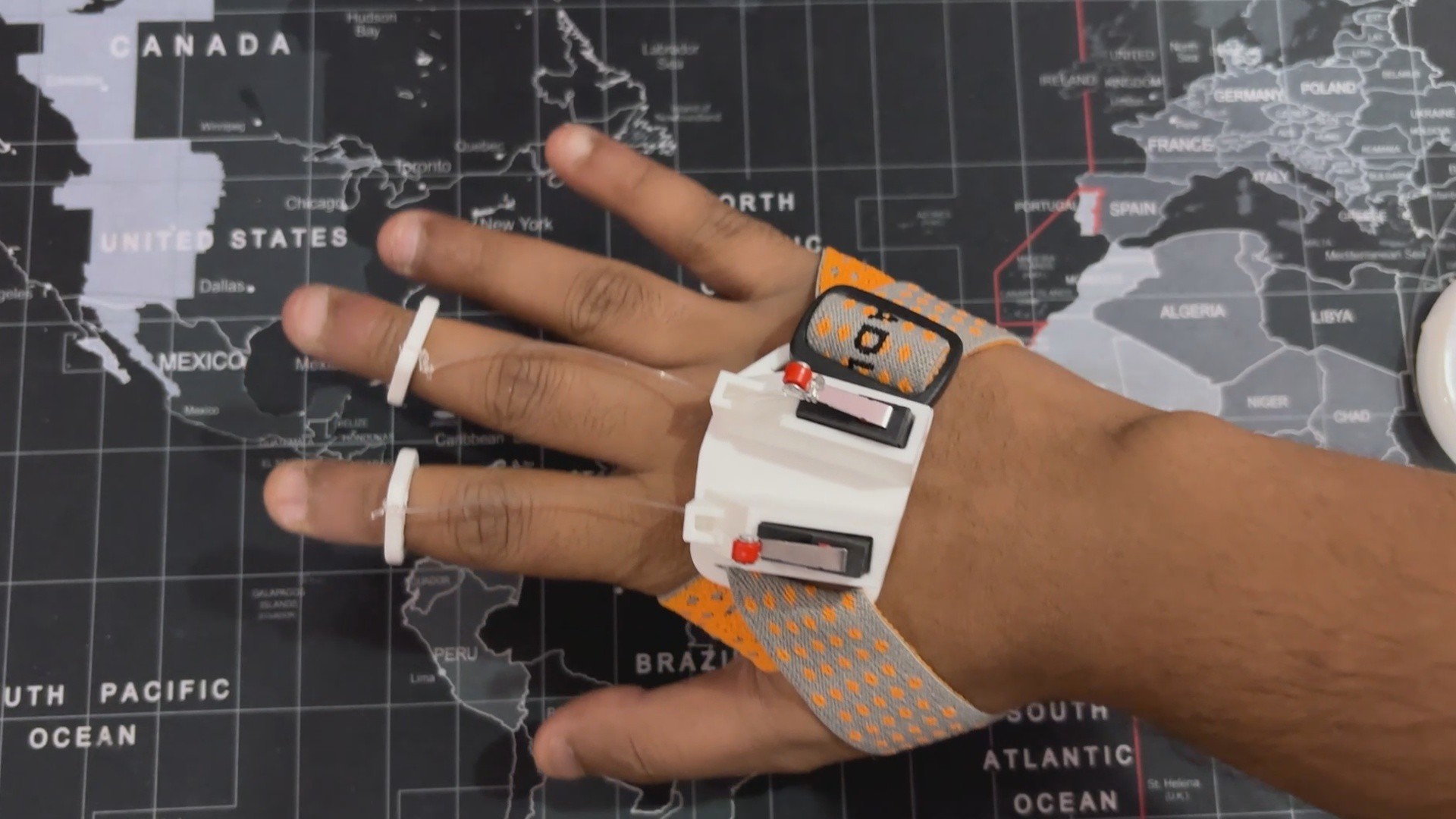
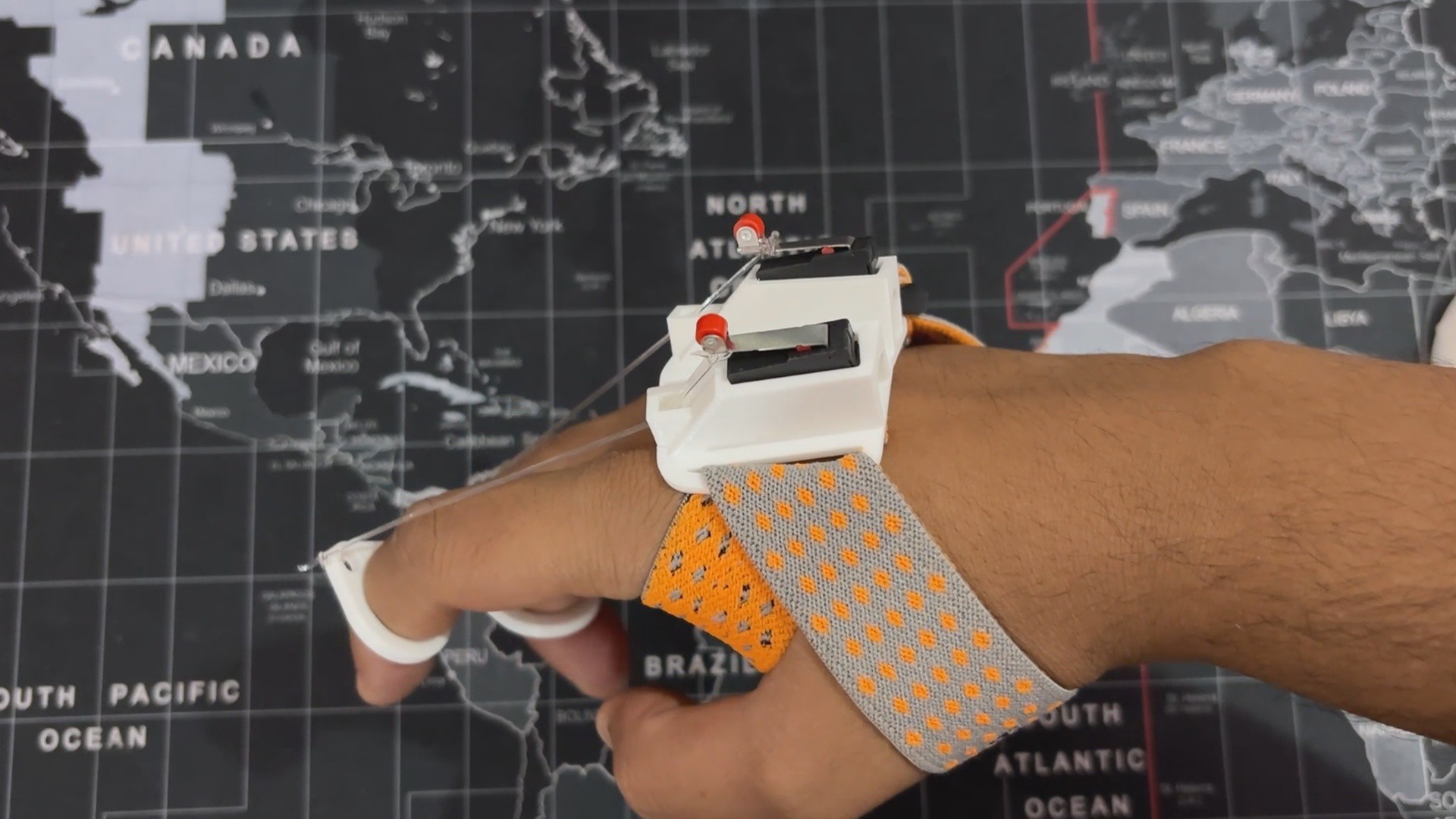
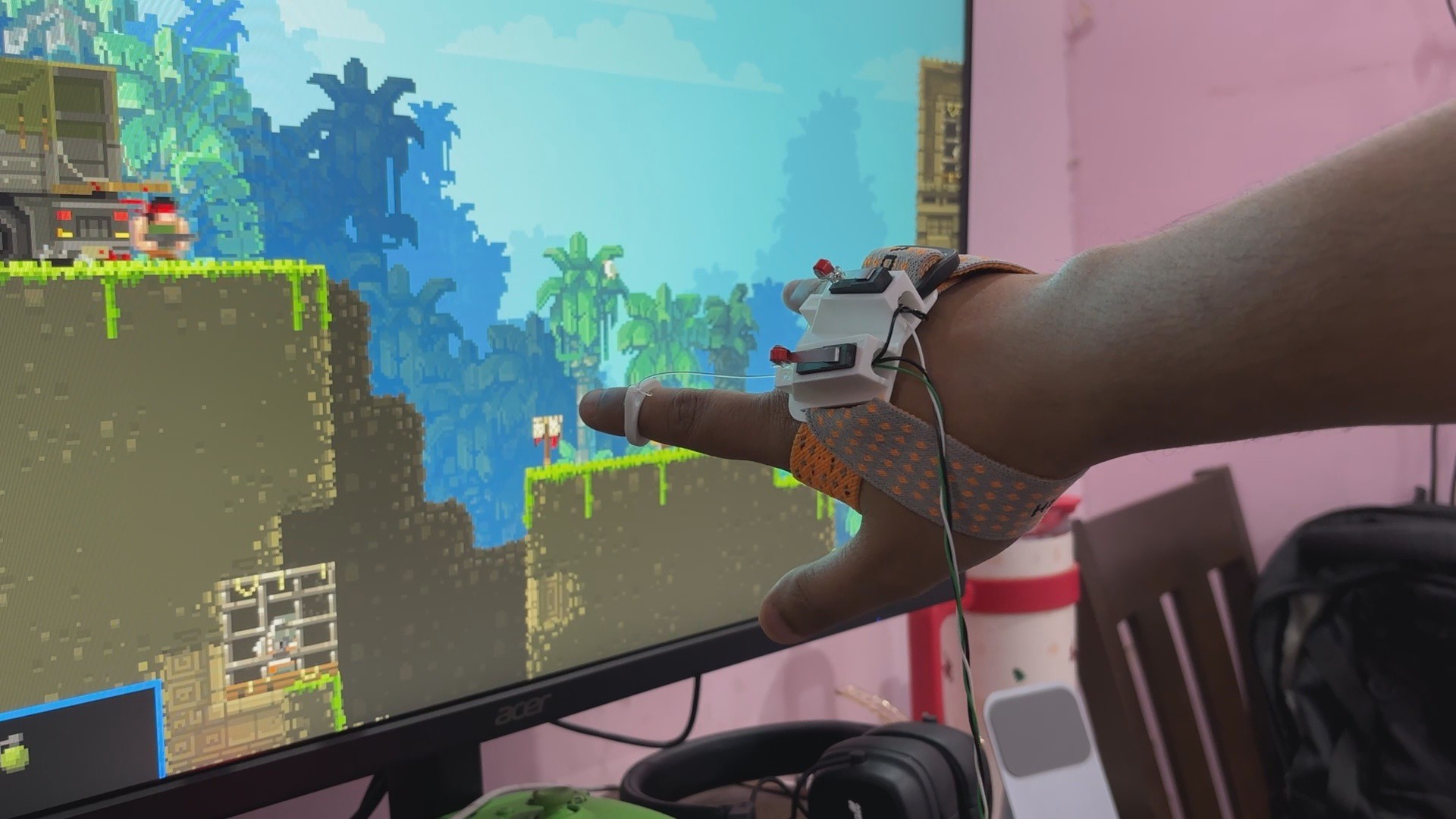
Our design has a wrist-mounted controller, which eliminates the need for holding a typical controller. Instead, it uses carefully placed limit switches that operate with finger movements, providing simple control by just curling or bending the fingers.
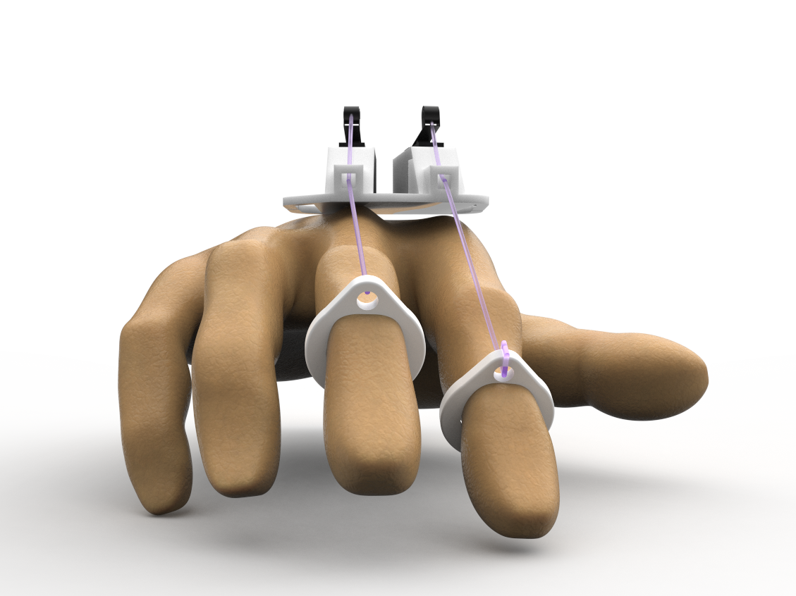
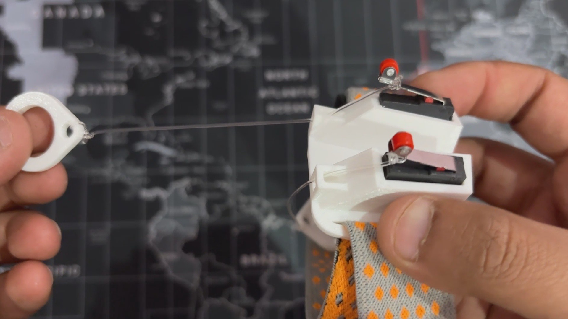
Each switch is linked to a lever mechanism, with a string connecting the lever to a ring worn on the finger. When the finger moves, the string pulls the lever, which triggers the switch.
We utilize two limit switches that are connected in parallel with the button inputs of our previously made SNES Mini controller.
This method provides an intuitive and ergonomic way to interact with games, reducing hand strain. It challenges standard control methods by allowing natural finger movements to drive games.
This article is about setting up this basic string-based wearable controller, so let's get started with the build.
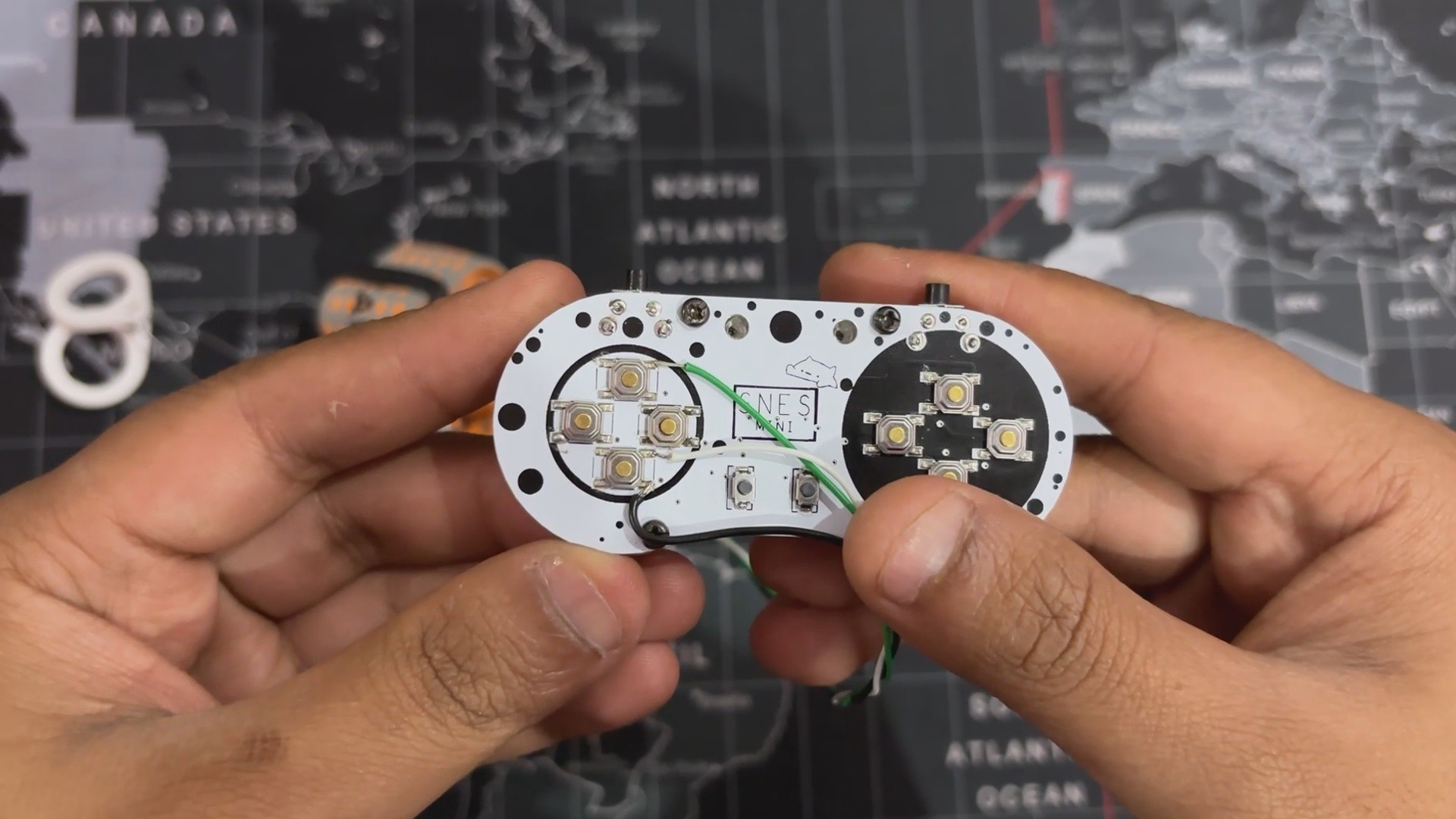
For this project, we are utilizing our previously made POCKET SNES controller as the base for this project. Base here means we are using this Pocket SNES as the main controller, and we will be adding our custom wrist-mounted contraption with this setup.
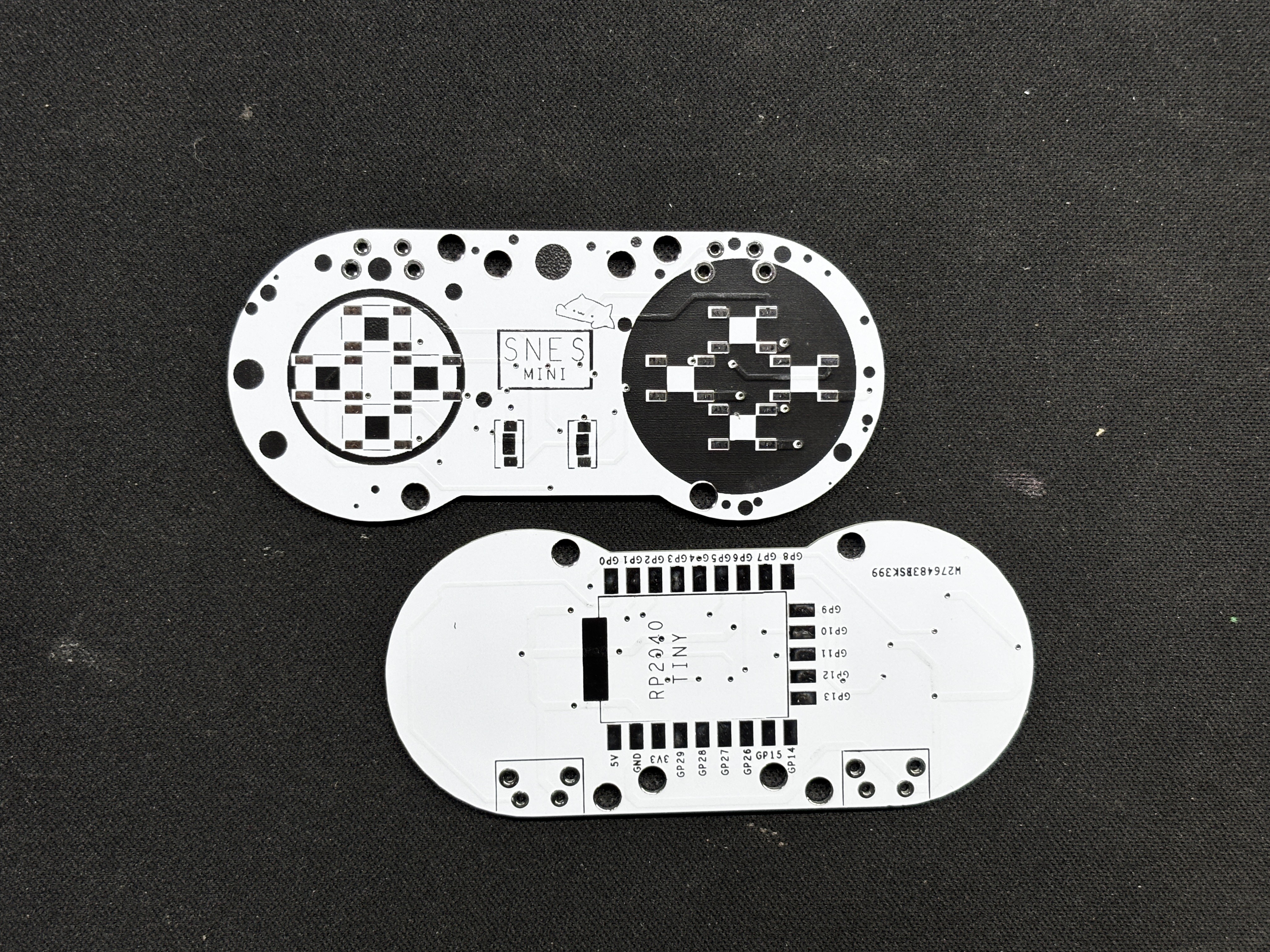
Let's have a recap of the project: the RP2040-Tiny mini development board, which is an SMD or module version of the Raspberry Pi PICO, serves as the controller brain.
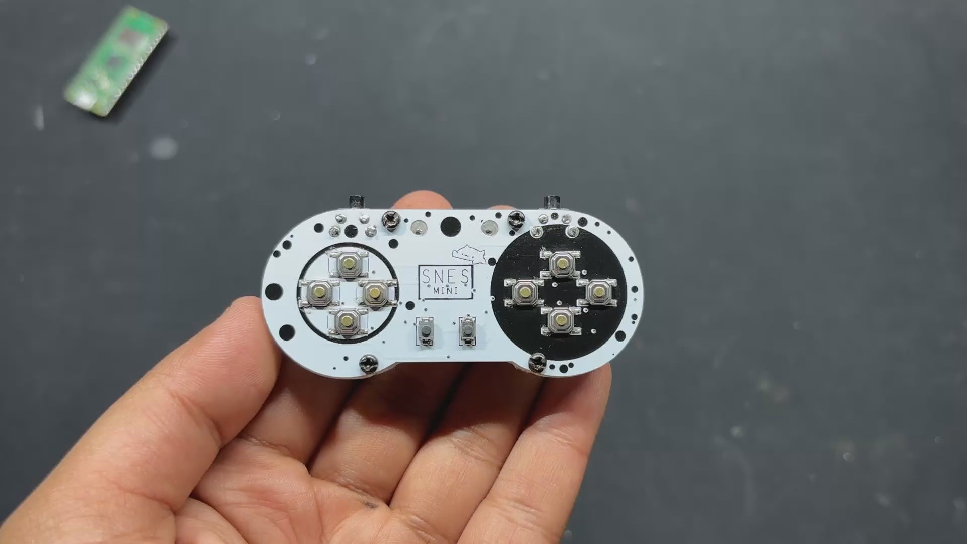
The RP2040 Tiny Module was installed on a controller-shaped PCB that had small SMD tactile buttons on one side and the RP2040 controller on the other.
To increase the controller's grip, an enclosure is added to the bottom side of the PCB, making it easier to hold. You can check out the full build guide about this project from the link below. https://www.hackster.io/Arnov_Sharma_makes/pocket-snes-9babf9
PCBWAY SERVICE
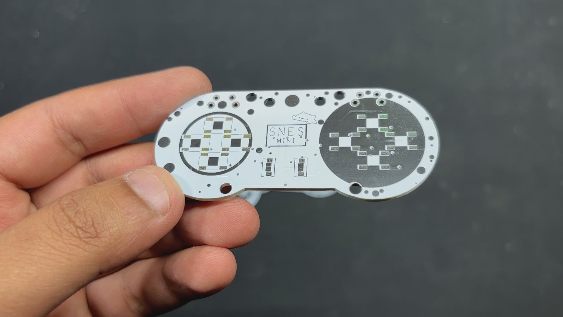
For this project, we are reusing the SNES Mini PCBs provided by PCBWAY. The order was placed for a white solder mask with a black silkscreen PCB.
PCBs were received within a week, and the PCB quality was outstanding. Here, we added a few design elements on the board's silkscreen layer to increase the aesthetic appeal of the project. PCBWAY made the custom layer properly, which shows their great PCB manufacturing capabilities.
Over the past ten years, PCBWay has distinguished themselves by providing outstanding PCB manufacturing and assembly services, becoming a trusted partner for countless engineers and designers worldwide.
You guys can check out PCBWAY if you want great PCB service at an affordable rate.
STRING CONTROLLER DESIGN
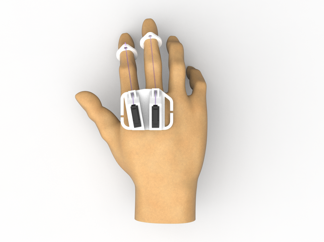
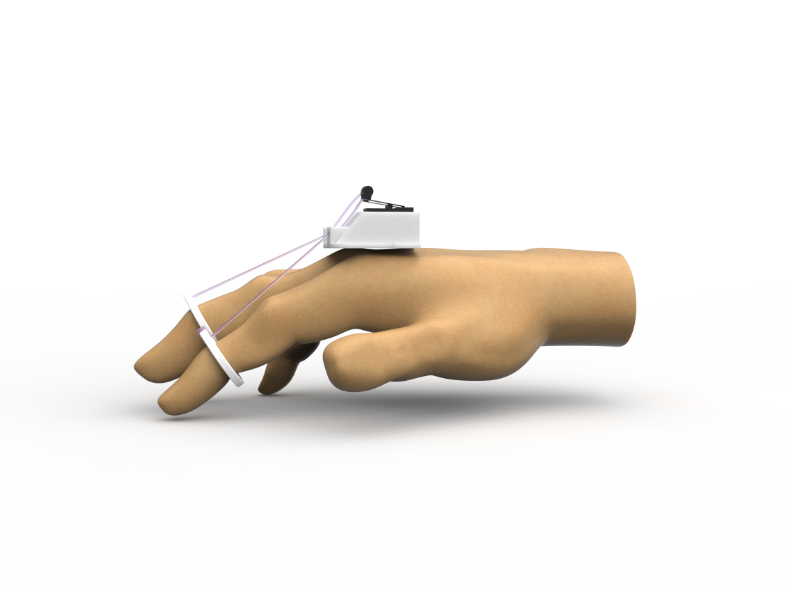
Let's have a look at the design of the Wrist Mount Part, which was really straightforward to put together. We just installed two lever switches near the knuckles of the hands, then modeled a holder to keep these two switches in place. Each switch faces the finger; the first switch is for the index finger, and the second is for the middle finger. Our goal was to add a string with a lever to these limit switches, followed by a ring-like part that will be put on both fingers. Because the string is attached to the switch's lever, when pulled downward, the switch registers a click, which is how our controller works.
This was merely for testing whether or not this idea works; therefore, we only put up two limit switches, but we could modify this setup to operate five switches utilizing our five fingers. After finishing the model, we exported the STL files for the Switch Holder and rings and printed them on our Creality K10 max with a 0.4mm nozzle and 0.2mm layer height.
BASIC SETUP
The assembly process for this small experiment was rather simple; limit switches were attached to their...
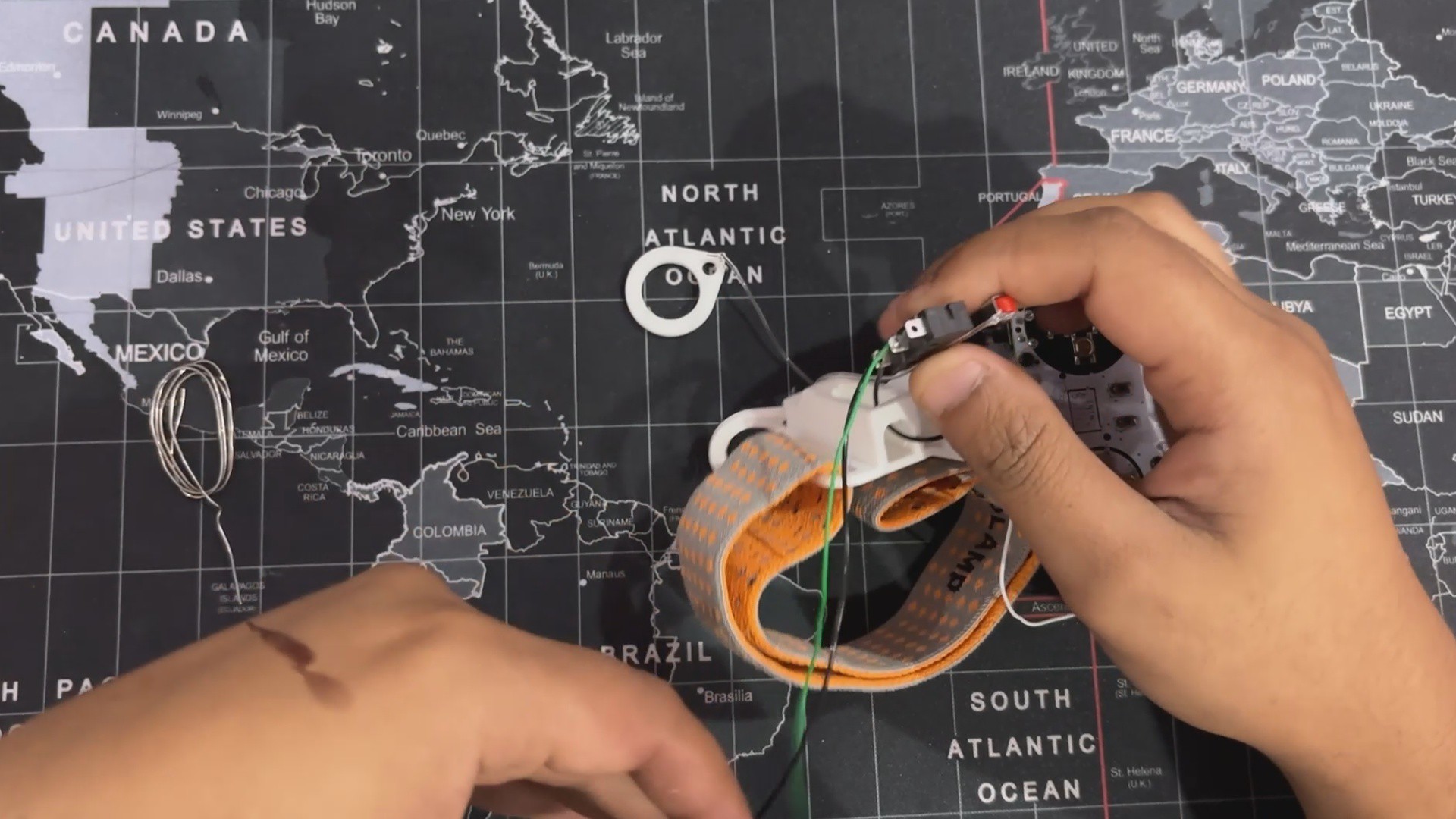
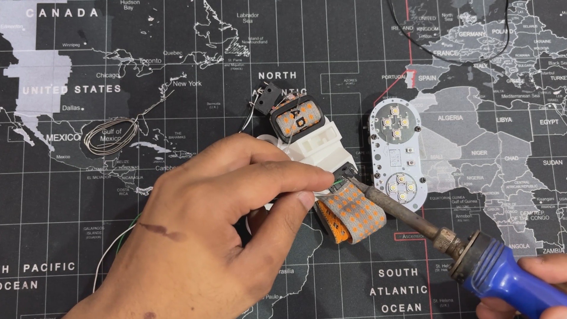
This is the main section of the project, which involves connecting the limit switches to the SNES controller.
We begin by soldering connecting wire to the first Limit switch's COM and NC terminals. We then route the wire through the opening on the back side of the holder and install the limit switch in its place.
We then repeated the process with the second Limit switch, connecting one wire to the COM terminal and then to NC, but this time we added a single short black wire to the COM terminal, which will be connected to the first Limit switch's COM terminal. This will link both limit switch COM terminals in parallel, allowing us to connect this wire to the GND of the SNES controller.
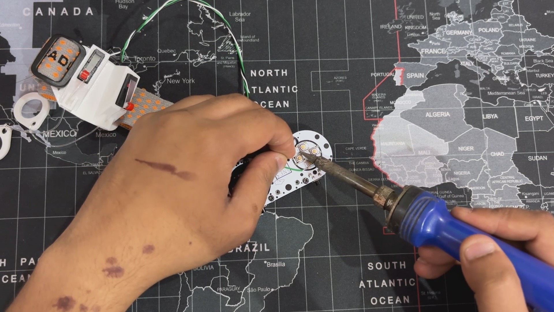
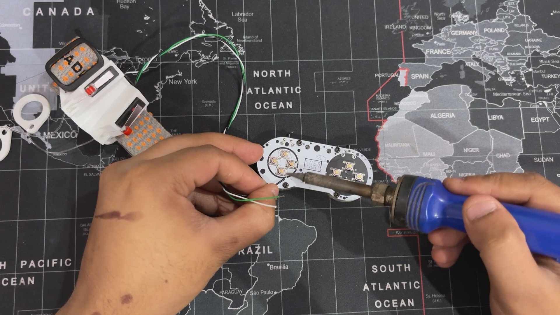
The three wires from the limit switches (COM, First Limit Switch NC, and Second Limit Switch NC) are connected to the SNES controller buttons. We connected a COM wire to the GND terminal of the SNES Controller. The first limit switch NC wire is attached to the left button, while the second switch NC wire is connected to the right button.
After attaching the wires, our setup is complete; now we'll add the new code to the SNES Controller and test it.
2
CODE
Here, we're using a revised version of the code from the previous SNES project. This code works with PICO as well as any HID-enabled Arduino or other development board, providing for smooth integration and functioning across multiple platforms.
#include"Adafruit_TinyUSB.h"// === Gamepad Setup ===#define NUM_BUTTONS 12constuint8_t buttonPins[NUM_BUTTONS] = {
0, 1, 2, 3, 4, 5, 6, 7, 8, 9, 10, 11
};
// Gamepad HID Descriptor (12 buttons)uint8_tconst hid_report_descriptor[] = {
0x05, 0x01, 0x09, 0x05, 0xA1, 0x01, 0x15, 0x00,
0x25, 0x01, 0x35, 0x00, 0x45, 0x01, 0x75, 0x01,
0x95, 0x0C, 0x05, 0x09, 0x19, 0x01, 0x29, 0x0C,
0x81, 0x02, 0x75, 0x01, 0x95, 0x04, 0x81, 0x03,
0xC0
};
Adafruit_USBD_HID usb_hid;
uint8_t report[2] = {0};
voidsetup(){
for (int i = 0; i < NUM_BUTTONS; i++) {
pinMode(buttonPins[i], INPUT_PULLUP);
}
// Setup USB HID
usb_hid.setReportDescriptor(hid_report_descriptor, sizeof(hid_report_descriptor));
usb_hid.setPollInterval(2);
usb_hid.begin();
while (!USBDevice.mounted()) delay(10);
}
voidloop(){
staticuint32_t last = 0;
if (millis() - last < 10) return;
last = millis();
// Clear report
report[0] = 0;
report[1] = 0;
for (int i = 0; i < NUM_BUTTONS; i++) {
if (digitalRead(buttonPins[i]) == LOW) {
report[i / 8] |= (1 << (i % 8)); // Set button state in report
}
}
usb_hid.sendReport(0, report, sizeof(report));
}
Let's have a Code Breakdown, and it's a simple one.
#include "Adafruit_TinyUSB.h"
Adafruit TinyUSB is added, which enables USB HID support on RP2040, allowing it to function as a gamepad.
This section is the descriptor that defines the controller as a USB HID device with 12 buttons. It tells the operating system how to interpret input from the controller. Each button has a corresponding bit (pressed or not).
This section creates a USB HID object (usb_hid) to manage data transmission and defines the HID report buffer (report), which stores button states before sending them.
Pin Initialization & USB Connection
void setup() { for (int i = 0; i < NUM_BUTTONS; i++) { pinMode(buttonPins[i], INPUT_PULLUP); } // Setup USB HID usb_hid.setReportDescriptor(hid_report_descriptor, sizeof(hid_report_descriptor)); usb_hid.setPollInterval(2); usb_hid.begin(); while (!USBDevice.mounted()) delay(10);}
This section Configures button pins as INPUT_PULLUP to detect presses and Initializes the USB HID device, setting the descriptor and polling rate, then Waits for the device to mount before proceeding.
Handling Button Input & Sending Reports
void loop() { static uint32_t last = 0; if (millis() - last < 10) return; last = millis();
This Section in the loop Ensures the loop updates every 10ms for smooth input processing and Prevents unnecessary processing, improving efficiency.
Detect Button Presses & Update HID Report
report[0] = 0;report[1] = 0;for (int i = 0; i < NUM_BUTTONS; i++) {if (digitalRead(buttonPins[i]) == LOW) {report[i / 8] |= (1 << (i % 8)); // Sets button state in report}}
This part Scans each button, checking if it is pressed (LOW state) and uses bitwise operations to efficiently store 12 button states in 2 bytes
Send HID Report
usb_hid.sendReport(0, report, sizeof(report));}
This section Sends the HID report to the computer, allowing button presses to be recognized.
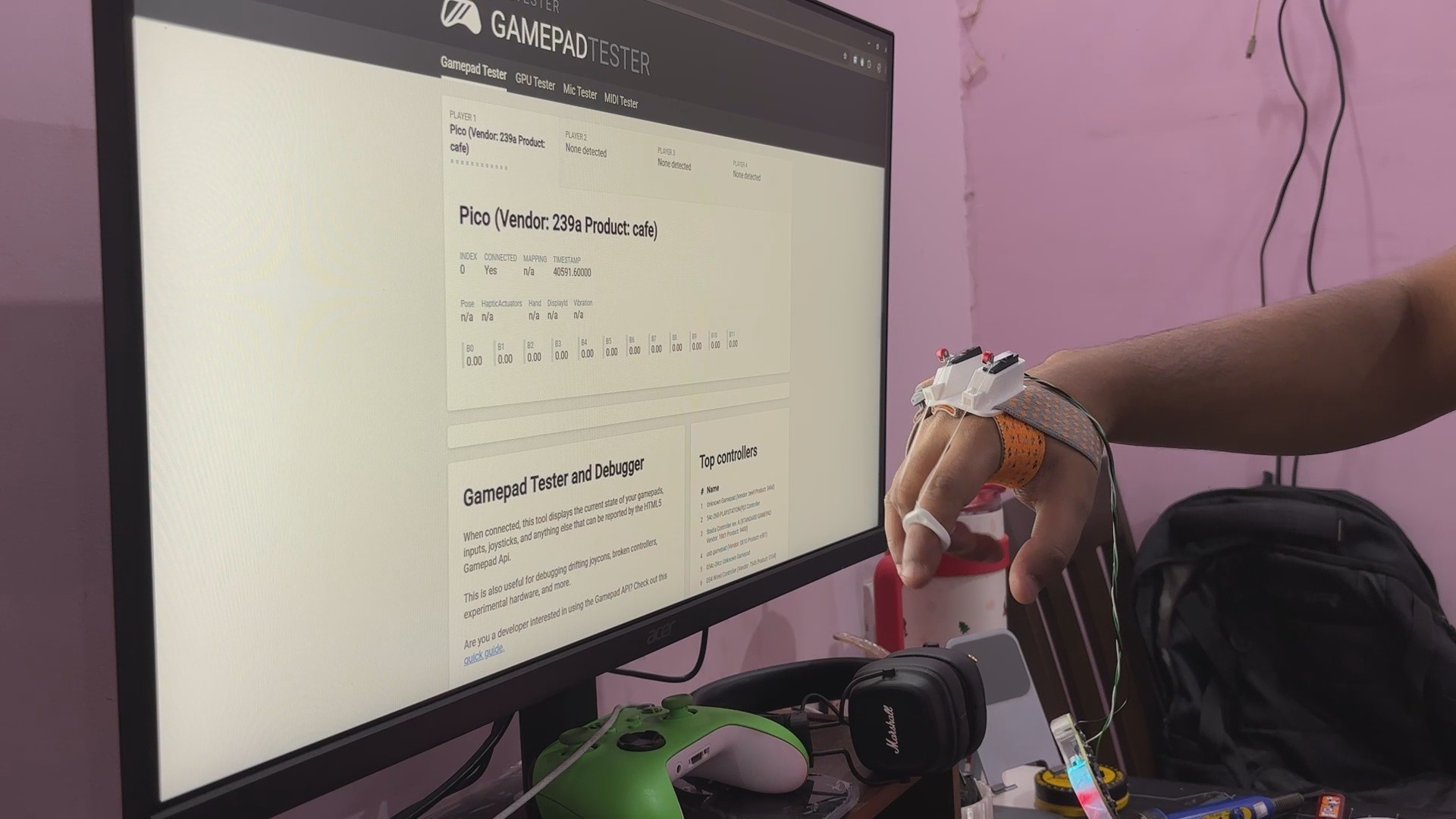
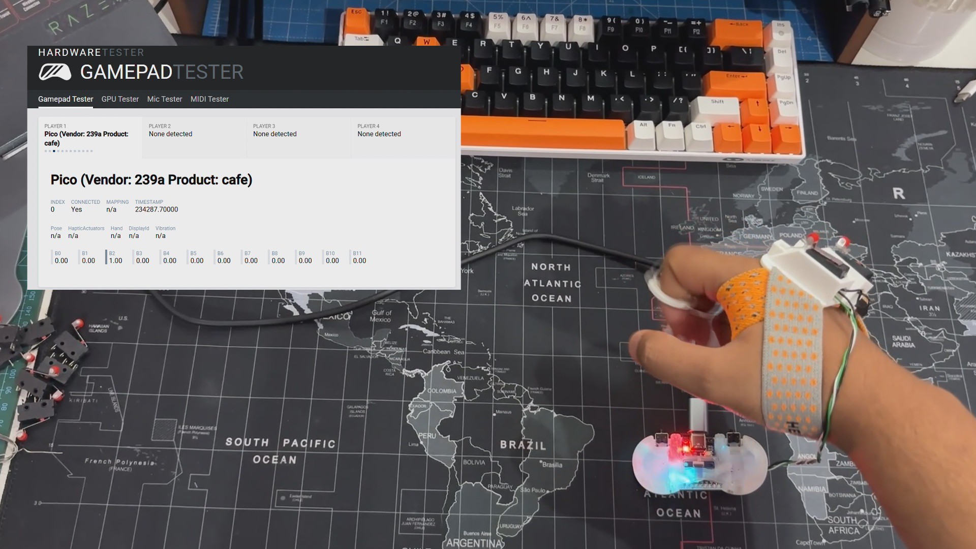
After uploading the code into our SNES Controller setup, we utilize a website called game pad tester to test that our button input functions correctly. Using this site, we were able to confirm that our device was functioning.
3
RESULT
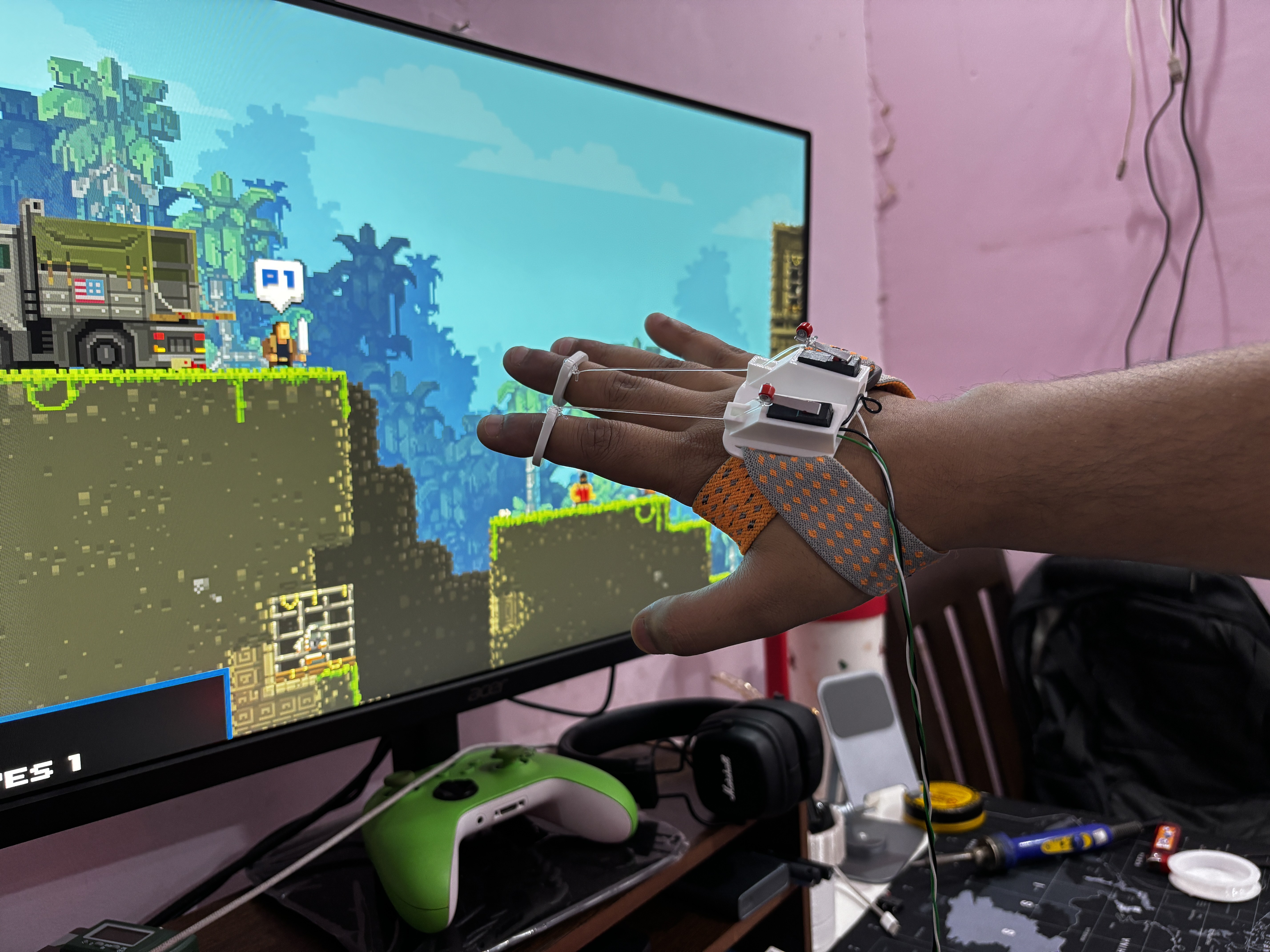
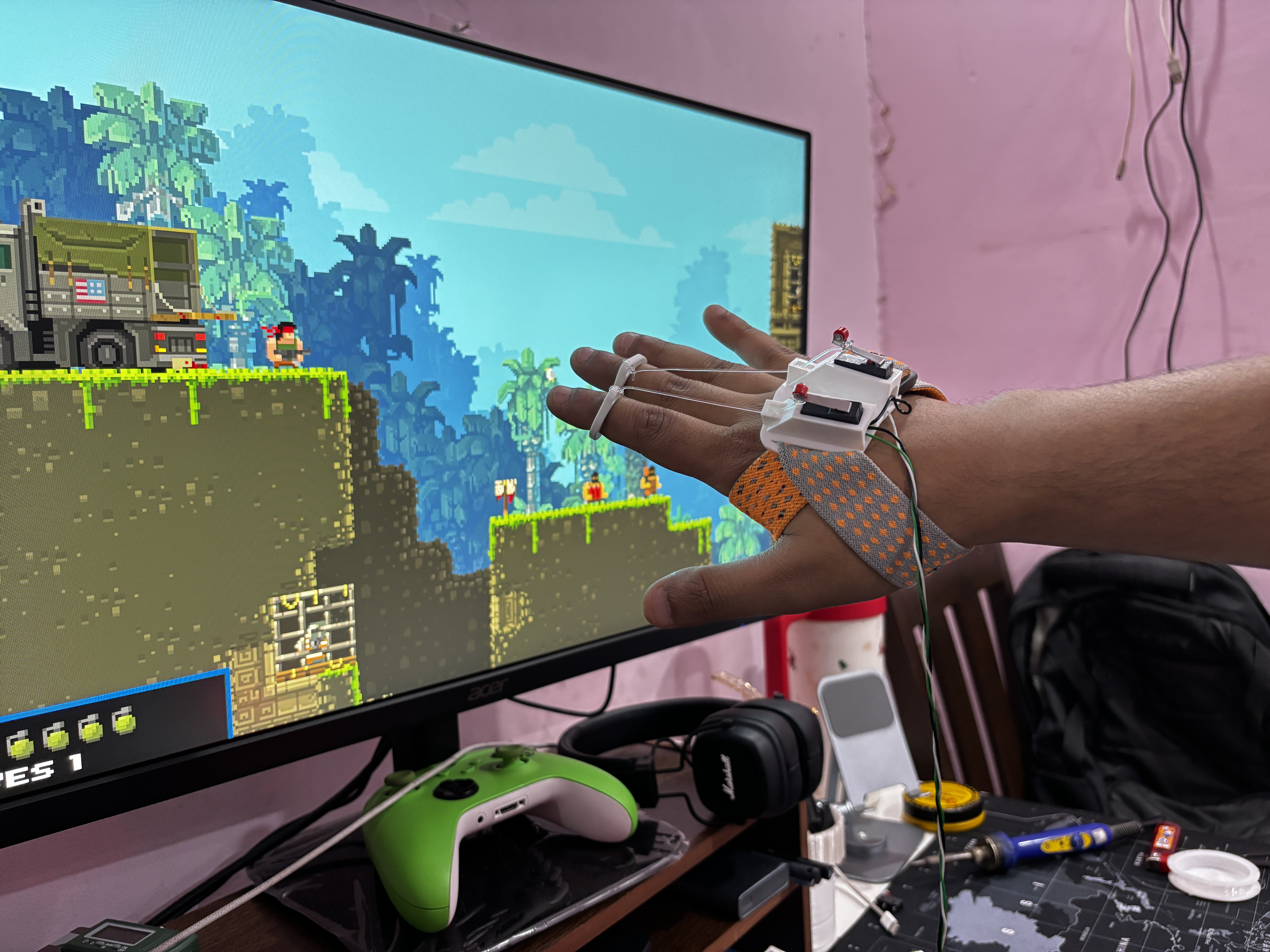
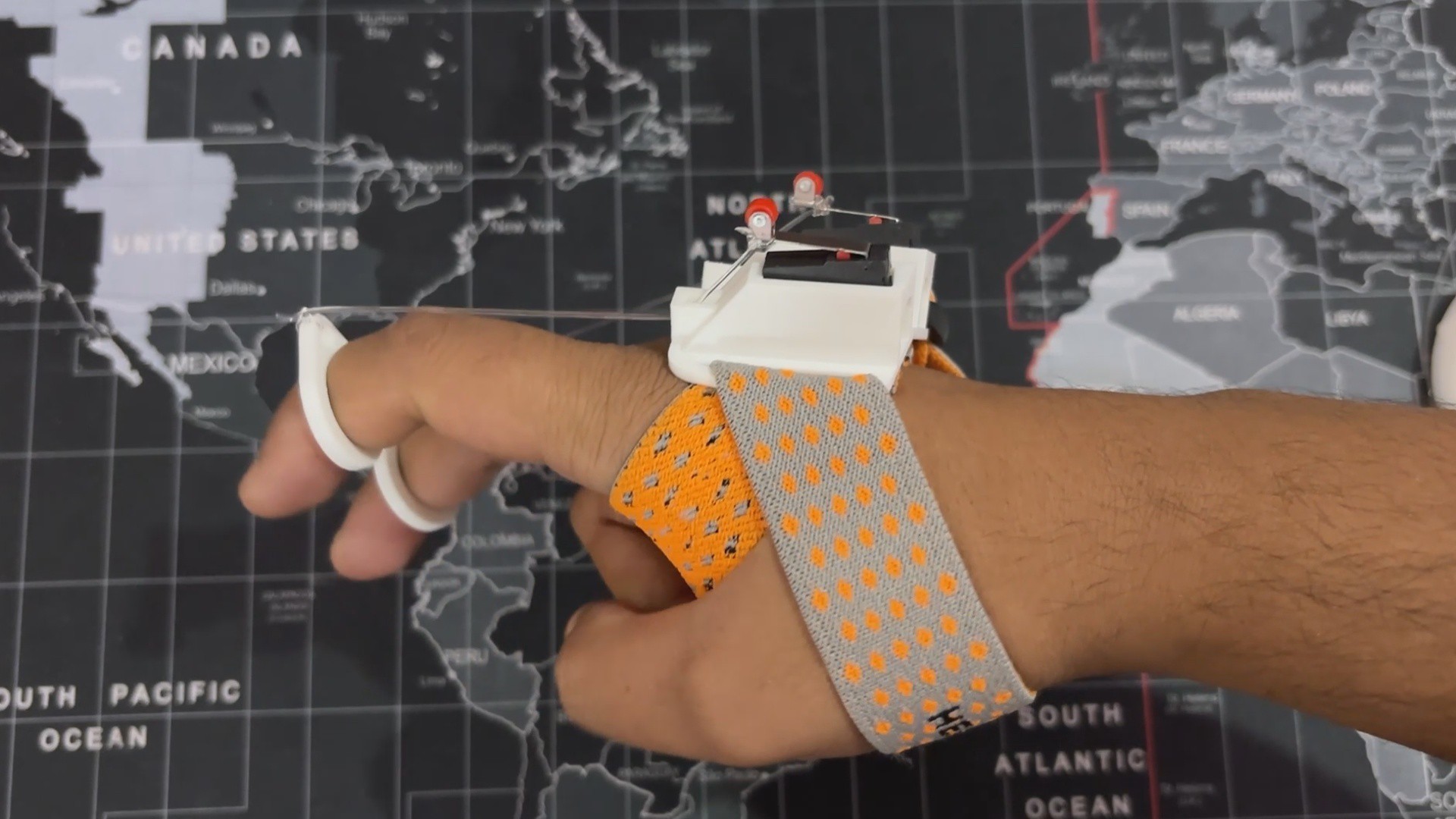
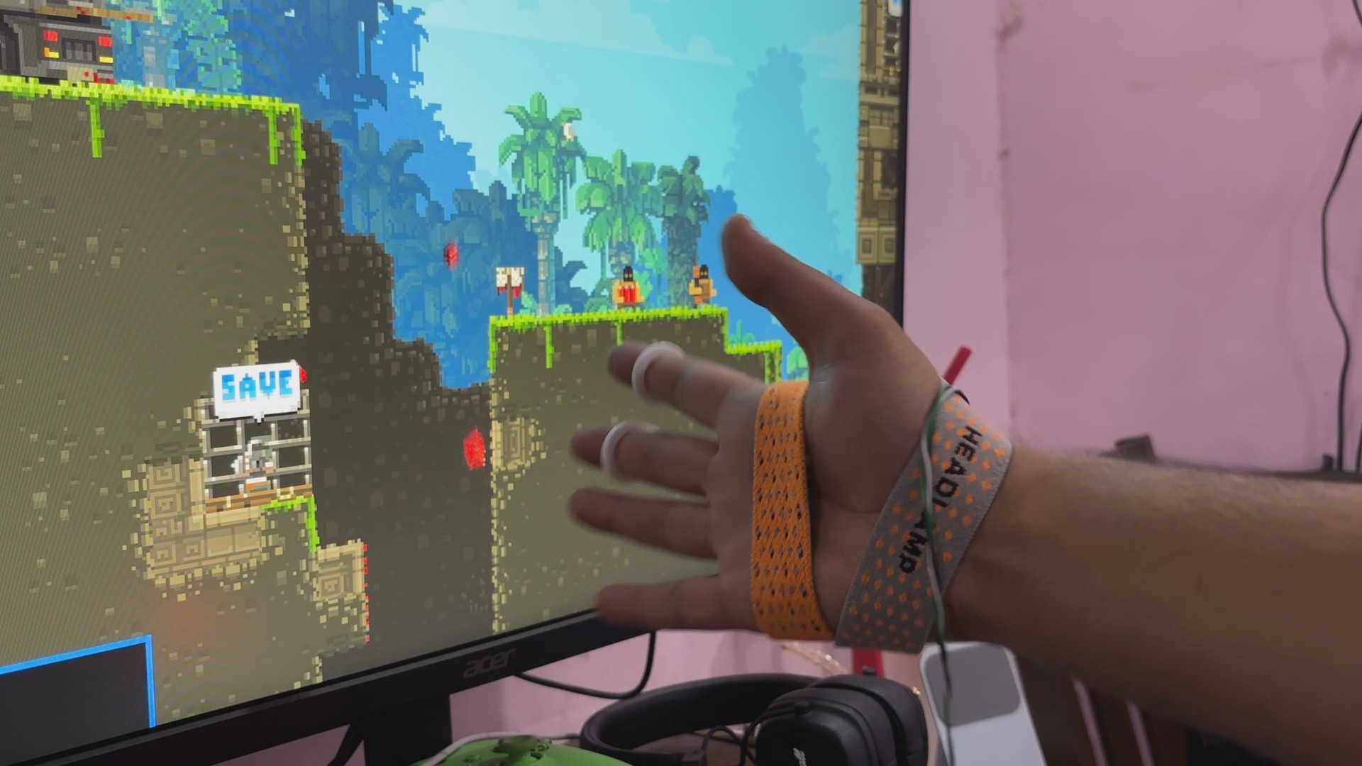
The end result of this experimental project is a wearable game controller that operates exactly like a standard one. What's the key difference? Instead of pressing buttons, movement is controlled using finger movements.
This was achieved through a simple string-based approach in which a limit switch is linked to a string. When the string is pulled downward, the switch triggers, pulling a GPIO pin to GND, which is detected by the Raspberry Pi Pico. This clever contraption allows intuitive movement control with only finger motions!
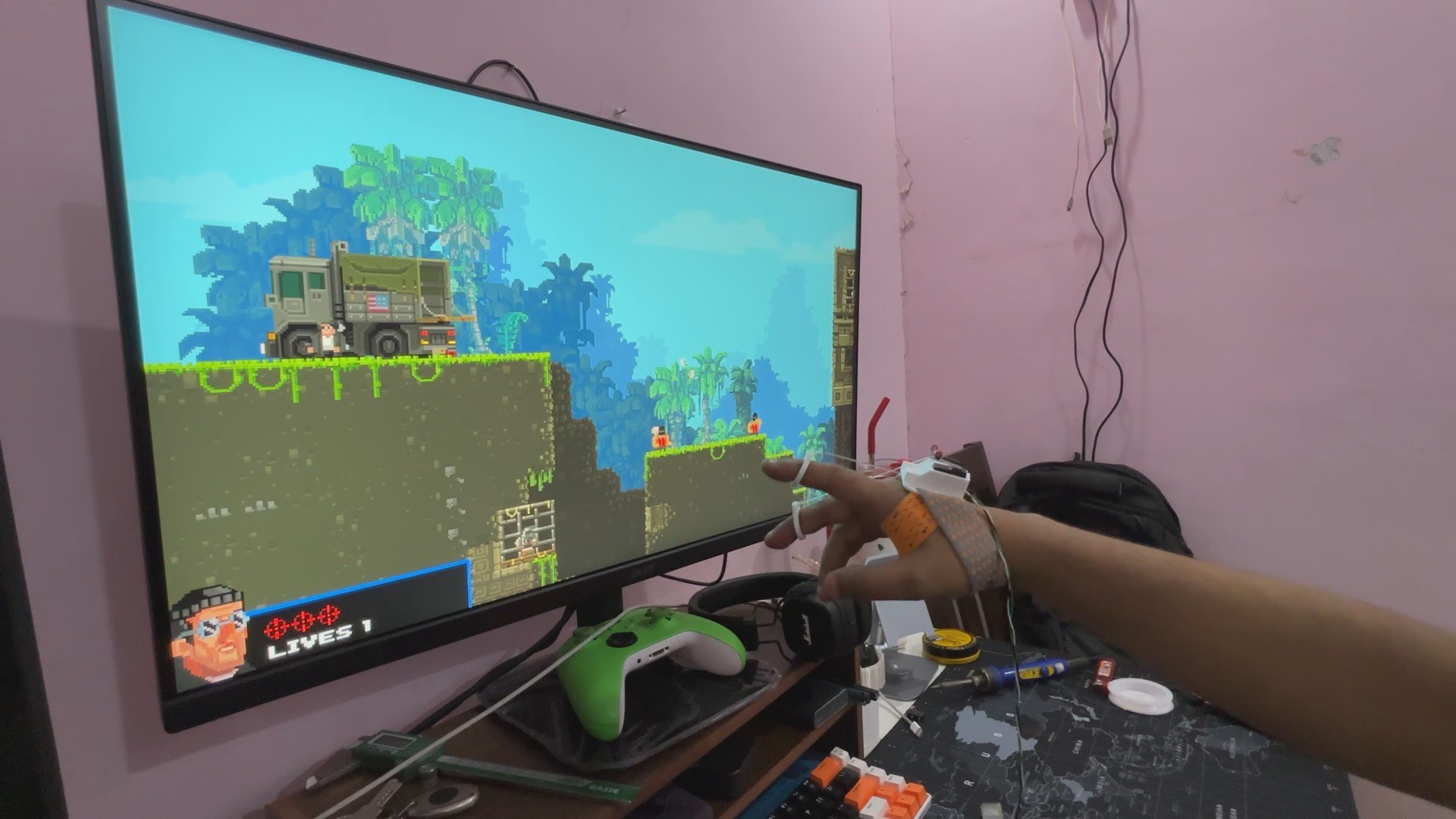
To put this to the test, we opened Broforce and mapped our controller in the Controller Mapping option. We set the first limit switch to move backwards and the second to move forwards.
We could control our character's movement with both fingertips, effortlessly moving it forward and backward. We couldn't use all of the features because the setup only had two buttons, but for an experimental project, this demonstration was ideal.
 Arnov Sharma


 David Brown
 victor
This is a great project, congrat!