 Bud Bennett
Feel free to ignore this and do your own thing. There is no "correct" method. Take the following as suggested procedure.
Step 0: Drill out the holes in the case lid to allow for trimming
I have no pics for this. Just drill out the 4 indentations in the case lid with a 2.5mm drill to allow access later.
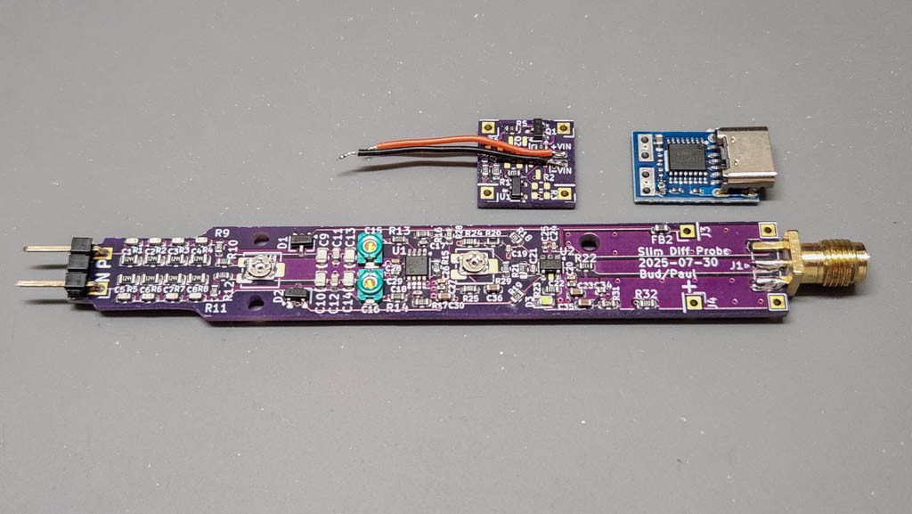
Step 1: Solder the PCBs and test them.
Test all three boards, and make sure that the probe can be compensated (although this could be fixed later.) Solder the power leads that go from the daughter board you are using to the appropriate trigger board. The PCBs below are for the 10MHz probe.
Step 2. Solder the pins to the daughter board.
Try to keep them as flush as possible on the top side of the board. If you have large solder bumps, remove them with solder wick.
Step 3. Glue the trigger board on top of the daughter board and solder the power leads:
I use a dollop of 5 minute epoxy. Make sure that the trigger board doesn't extend past the front of the daughter board. (A side note at this point. Notice that the USB-C connector extends past the trigger board edge. This will make it easier to fully seat the USB-C cable.)
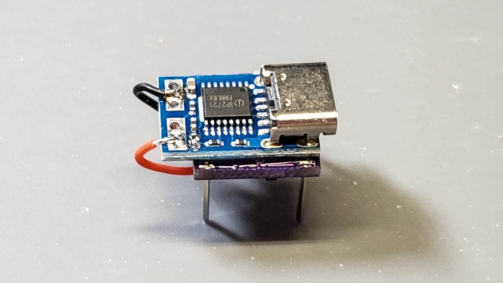
This trigger board is the shortest one that I know of at present -- it's only 10mm x 16mm. The design will accept a trigger board length up to 23mm, but you might have to change how the power leads are soldered to avoid interference with objects in the case.
Step 4. Solder the daughter board assembly to the probe:
The spacing of the daughter board above the probe PCB depends upon the thickness of the trigger board. I think the most straightforward method is to use the bottom case section to help align the board, as shown below. Get everything lined up and solder the four posts in place. Cut off the excess post material.

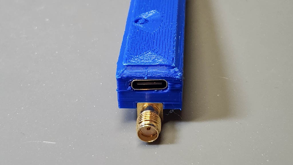
When you assemble the probe body into the case it should fit perfectly:
Step 5. Screw the two halves of the case together.
I don't have any pics of this. I use two M2x10mm screws for the front, and M2x16mm for the rear. Unfortunately, the M2x16 is too long and I must cut it 4-5mm shorter (after cutting threads in the lid first).
At this point your are most likely finished. But you should perform a re-calibration/compensation of the probe before you use it. If you wish to shield the probe from unwanted sensitivities, then read the next log.
Discussions
Become a Hackaday.io Member
Create an account to leave a comment. Already have an account? Log In.