 Bud Bennett
The probe can be used without shielding, but just laying it flat on a bench will cause the CMRR to degrade (or improve). Moving your hand anywhere near the front part of the probe will create parasitic capacitance that upsets the equilibrium of your trimmed capacitors.
I tried several shielding scenarios before settling upon the following. Here's what doesn't work: placing copper tape inside the case -- it is too close, and will disrupt the trim settings beyond what can be compensated; placing copper tape directly upon the under side of the attenuator section of the PCB -- this is a disaster, the copper ground plane was left off this area for a very good reason (but I tried it anyway.)
Paul used a different method to shield his probes. You can check out what he did here.
After you've shielded the probe it will be mostly insensitive to normal handling. By "mostly" I mean that the CMRR will not be affected more than a couple mV when you manhandle the probe. Some of my probes don't show any sensitivity to handling. I did not test it further.
Step 1. Run copper tape from the SMA connector to in front of the two capacitor trim holes, as shown.
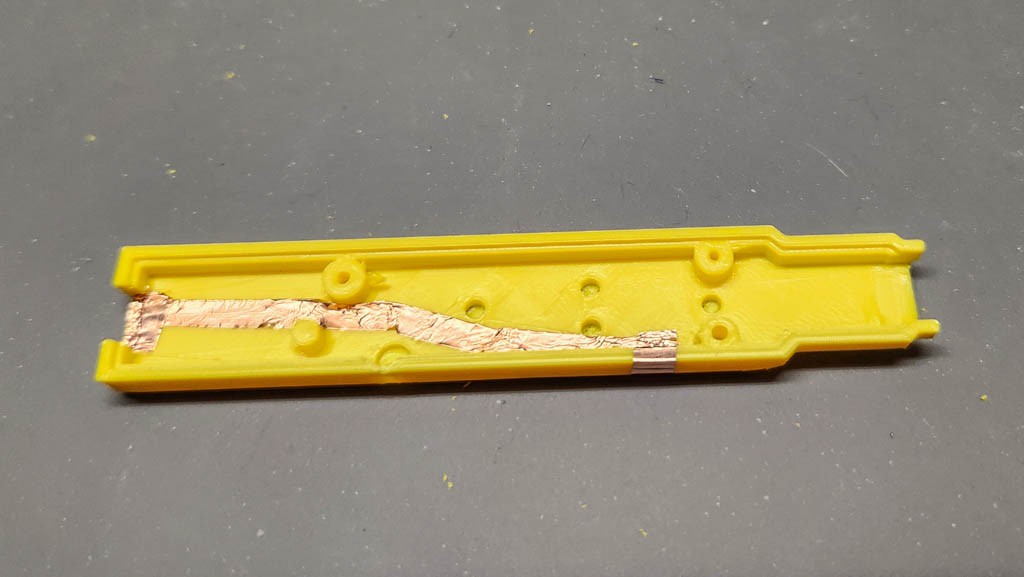
There are three pieces of tape in the above fuzzy photo. Use a thin strip to go from the SMA cutout, winding it way to avoid the trim holes and LED area, past the capacitor trim holes. Then put two additional pieces of tape: one to extend the coverage at the SMA cutout, and another to connect the end of the first strip to the outside of the case.
Make sure than these pieces of copper tape are connected with reasonably low resistance. Get out your DVM and measure the resistance from the SMA cutout all the way to the end of the path. If you aren't getting less than 200Ω, then try poking a bunch of holes where the different copper tape sections intersect. You can use your sharp DVM probe tips to do this or a pin. This is REALLY IMPORTANT! If you don't have a GND connection to the shielding then it will not work properly. (Trust me on this. I originally thought that the adhesive for my copper tape was conductive -- it was not -- hence the perforation procedure.)
Step 2. Wrap the area over the attenuator.
I don't really need to tell you how to do this...do I? Here's a photo of the end result:
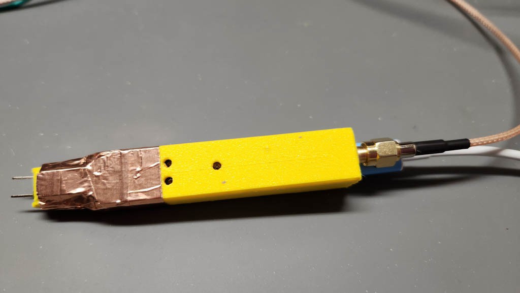
I used strips about 10mm wide it's not very pretty, but that's not the point. It gets covered up later. Again, make sure that you have a good connection to the copper tape all the way back to the SMA housing.
Step 3. Redo the Trims.
You need to redo the capacitor trims, and maybe the offset trim at this point. They are easy to access. The DC CMRR trim is not accessible without punching a hole to gain access. You shouldn't really need it if you trimmed it properly previously.
If things don't work out, then you might need to cut the two halves of the case apart and make some more serious adjustments (I did a couple of times.) You can leave the copper tape in place and just place a strip of tape to connect the two halves together -- making holes with pins or probe tips.
(By serious adjustments I mean replacing C11/C12 with smaller capacitors to allow you to get a flat compensation.)
Step 4. Cover It Up.
I used 15mm black heat shrink tubing. It does the job, but I had to stretch it out a bit before slipping it over the shielding. Here's the end result (with a change in color.) I doesn't look that bad, but I'm not showing you the printing on the heat shrink on the other side.

You could also use electrical tape. It is a bit shinier, and a bit less pretty (I tried it.)
Discussions
Become a Hackaday.io Member
Create an account to leave a comment. Already have an account? Log In.