 Jorisclayton
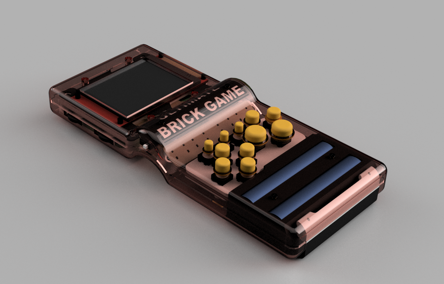
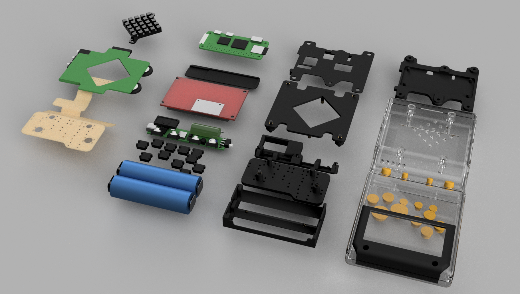
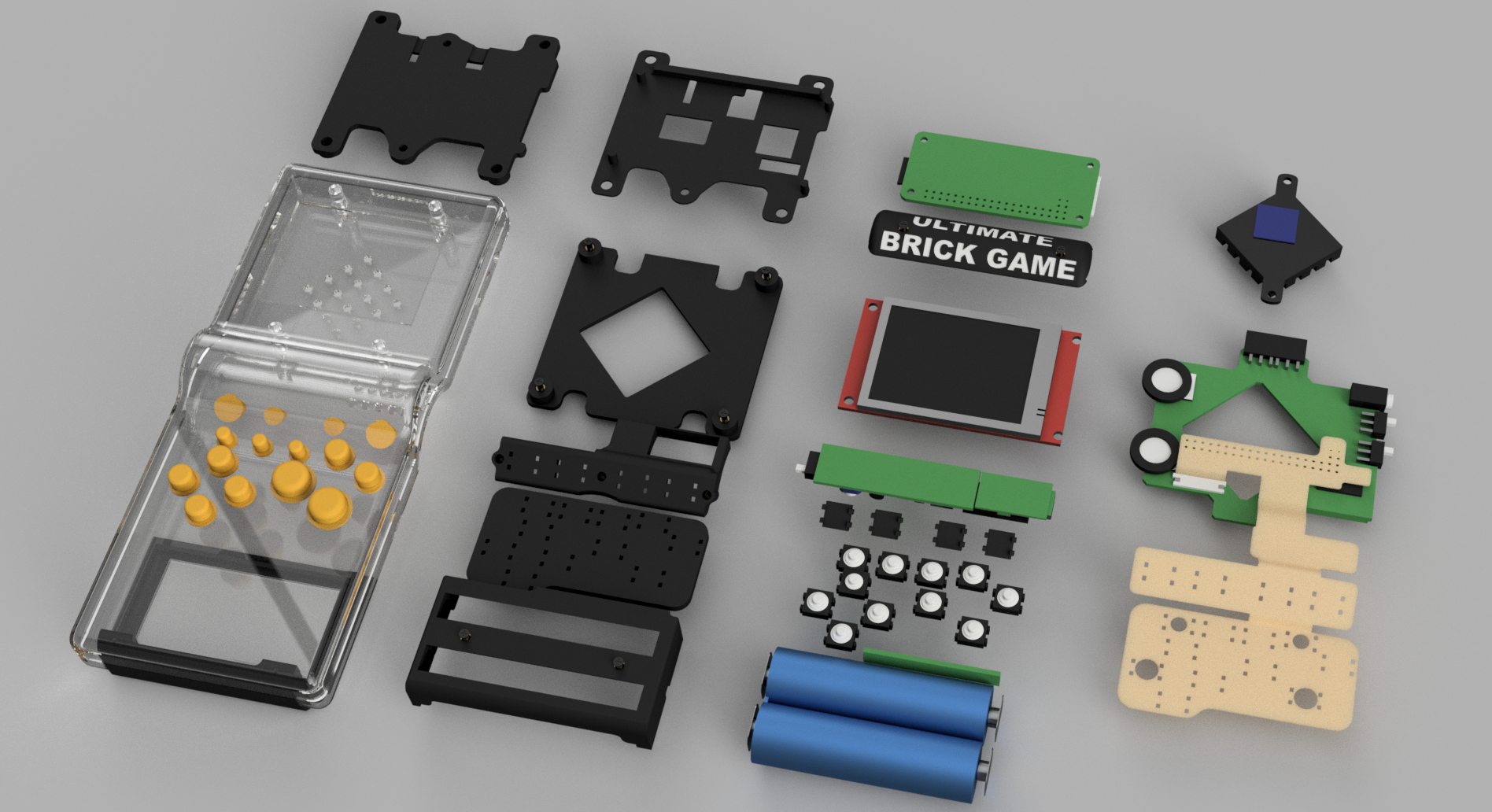
I'm ready with the V3 design. The 3D models are fine; I’ve already printed and tested them, and they fit properly. I created a complete 3D model of the whole console to help, since the components are getting very close to each other and the available space is disappearing quickly. I'm currently working with a version that I like to call V2.5, as it was made to test the button positions and the internal structures for the V3. The new controller layout works much better than in V1 and helped me identify the problems I needed to solve to design this new version.
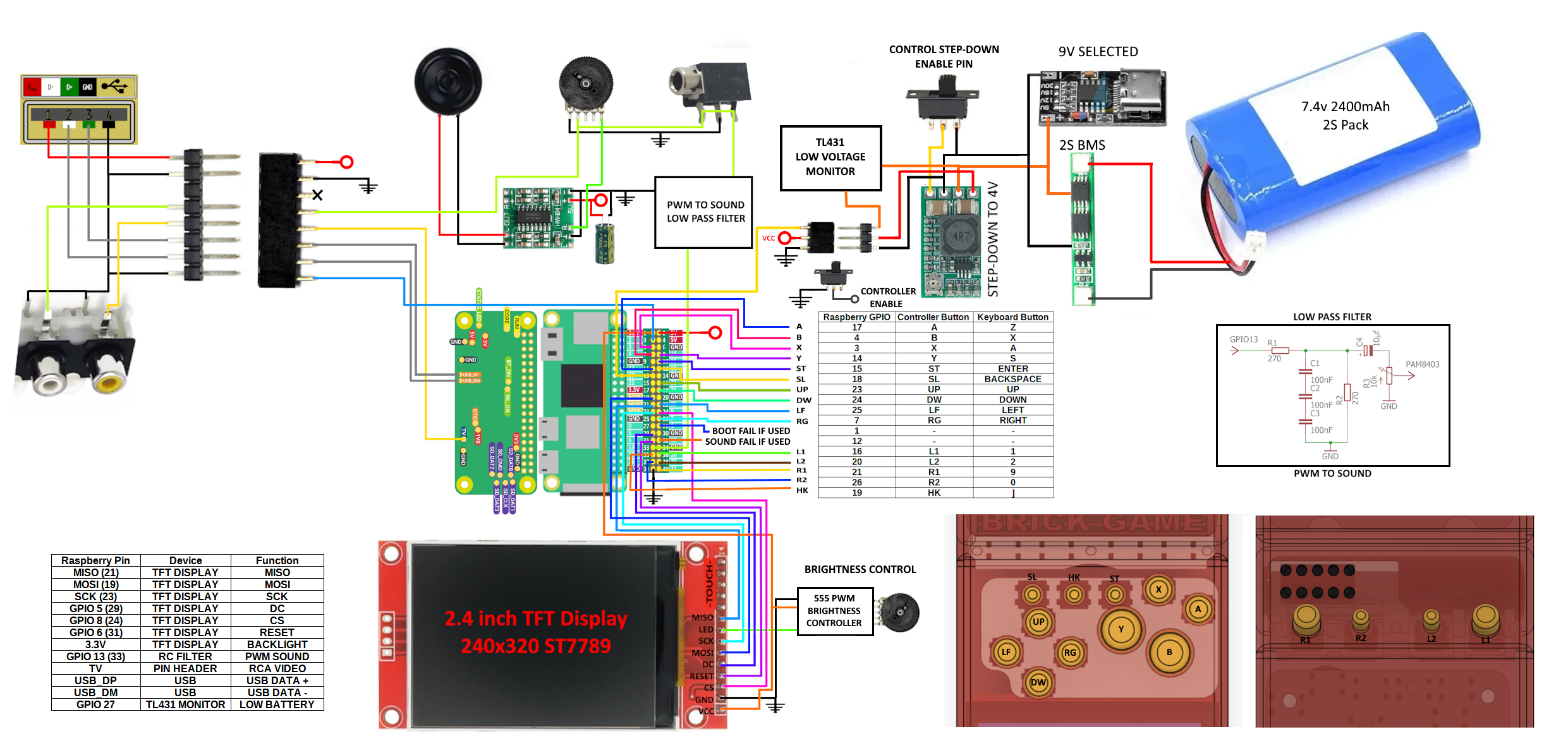
The software side will change just slightly, as V3 will include a Low Battery Warning to help save the game before a sudden shutdown. Some electronic components also need to be modified. The Raspberry Pi works fine when connected directly to a 3.7V source (operating between 4.2V and 3.2V), but the BMS cuts off the battery when it reaches around 2.6V — which seems to be normal behavior. However, this causes the system to crash before it powers down cleanly, so the handheld can be turned on again only to crash repeatedly.
V3 will also feature a display brightness control, implemented through a rotary potentiometer similar to the one used for volume. Currently, in V2.5, the potentiometer is wired directly to adjust the TFT’s supply voltage — and while it works, it doesn’t provide perfect control. In the new version, I plan to build a PWM-based dimming circuit using an SMD 555 timer, which will offer smoother and more stable brightness adjustment.
Additionally, V3 will include three On/Off switches with different functions: one to mute the audio, one to disable the controls (useful when storing the handheld while keeping it powered on, preventing unwanted input), and a third switch simply to power the system on and off.
I came up with a solution to monitor the voltage, but distinguishing 3.2V from 2.8V is difficult due to how close those values are. I also couldn’t find a MOSFET that works well in that range, and a simple TL431 circuit wouldn’t function properly at these voltages. So I decided to switch to a 2S 2400mAh battery setup. With that, I’ll use a very compact and approximately 97% efficient step-down converter (I tested it with an electronic load and it performed really well). This circuit includes an enable pin, which will serve the same purpose as the MOSFET I used before, eliminating one component.
For the battery monitor, I’ll build a small circuit using a TL431 and some resistors, which will pull a GPIO pin LOW when the battery level drops below 6.4V, indicating that the battery is nearly empty. The TFT display will then show a warning for the user, and the driver I’m using can handle this input.
The 3D models will now be updated to fit a PCB. Yes, I’m considering using a printed circuit board to connect the electronic parts to the Raspberry Pi and the controller. I’ll use three PCBs: one of them will be a flexible board that connects the buttons to the main board via a flex connector and connects to the Raspberry Pi through solder points on the GPIO.
I'm not yet done with the final electronic design, but I’ll work on that as soon as possible and try to build one. Currently, the V2.5 uses a lot of wiring (much thinner than what I showed in previous pictures), and it’s a bit complicated to assemble and troubleshoot — sometimes I need to desolder parts just to open things up, and it’s a mess.
I’m already enjoying the console. I’ve played NES and SNES Zeldas, PS1 Spyro, and all the SNES Donkey Kong Country games — they all run great and the controllers fit well. For N64, I’m still having trouble configuring the controllers properly, but they work okay, and I’ve already played some Mario Kart 64 races. I’m having a lot of fun building this project.
If anyone wants to build one of these, I’ll be happy to help as much as I can, but please wait until the V3 is finished, because I still need to fix some things and I’m sure new problems will appear once the final version is alive.
Below are some images of the new 3D models. I uploaded them to Thingiverse, along with the new (unfinished) schematic that will be used in V3. I plan to make a proper version in Eagle or EasyEDA in the future and use it to manufacture the PCBs. But first I need to run more tests and create some custom libraries for the components I plan to use.
3D files are available here: https://www.thingiverse.com/thing:7107931. They include parts to assemble the console and templates to modify the original Brick Game shell.
I’m open to suggestions — feel free to share any ideas or feedback.
Discussions
Become a Hackaday.io Member
Create an account to leave a comment. Already have an account? Log In.