 retrobyte
First challenge: interface the Nokia N97's original keyboard.
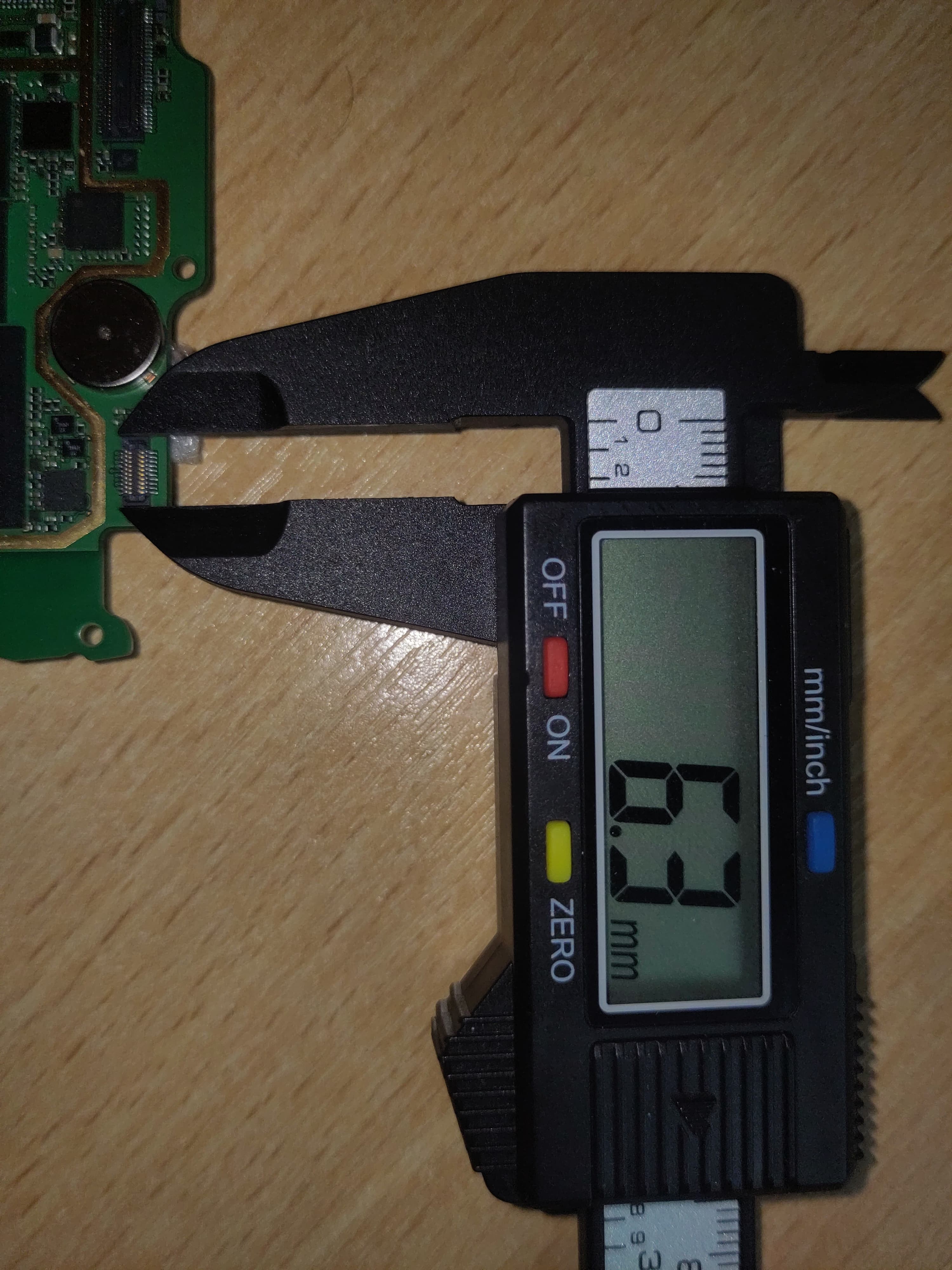
I desoldered the 0.4 mm pitch FPC connector (X4401) from the N97 mainboard. With no microscope or stencil, I used a combination of:
-
Tinning pads via drag soldering
-
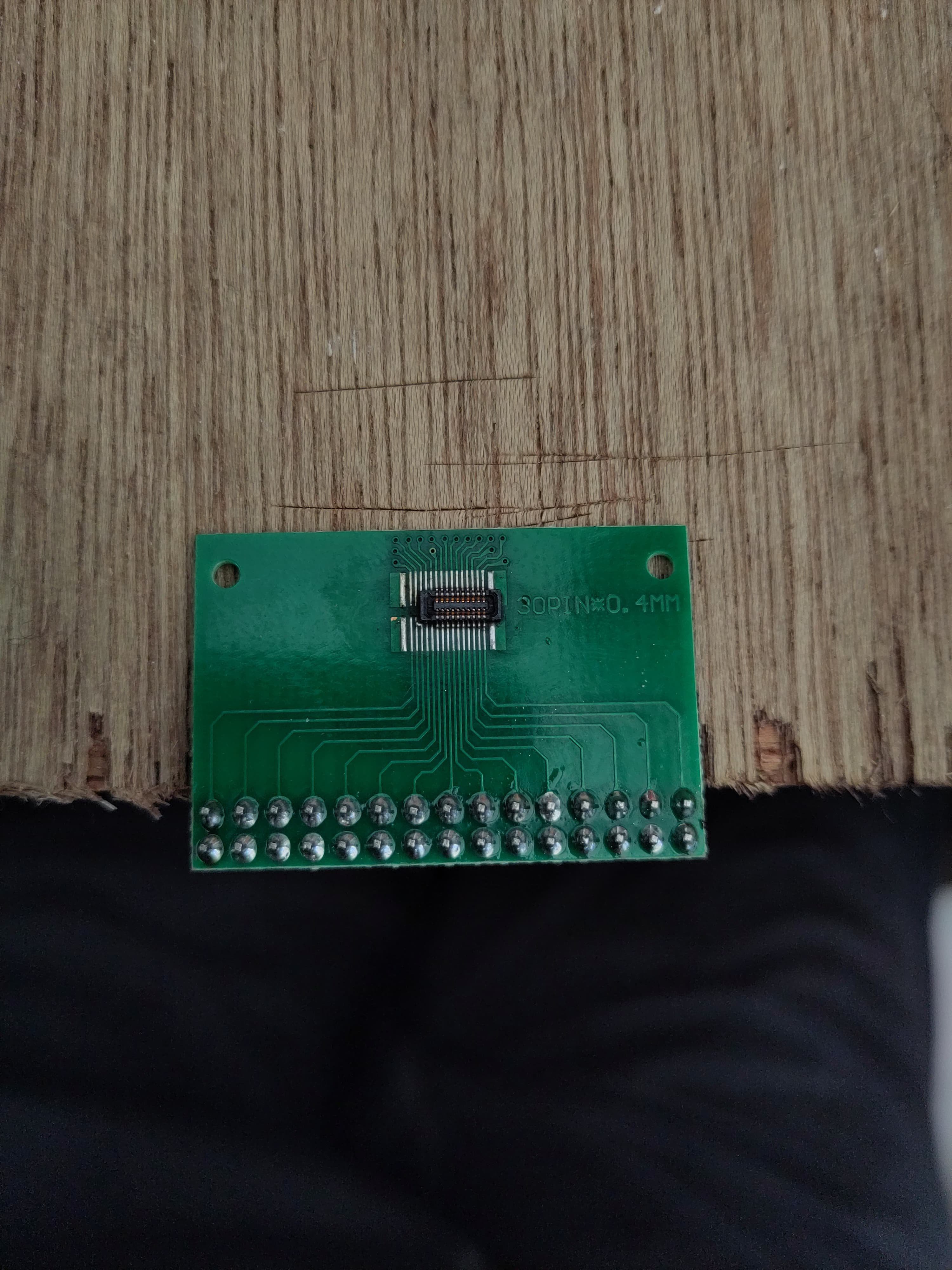
Reflowing with hot air to seat the connector
-
Final drag pass with flux to clean and confirm joints
First try — no bridges, no lifted pads. All 20 pins mapped successfully.
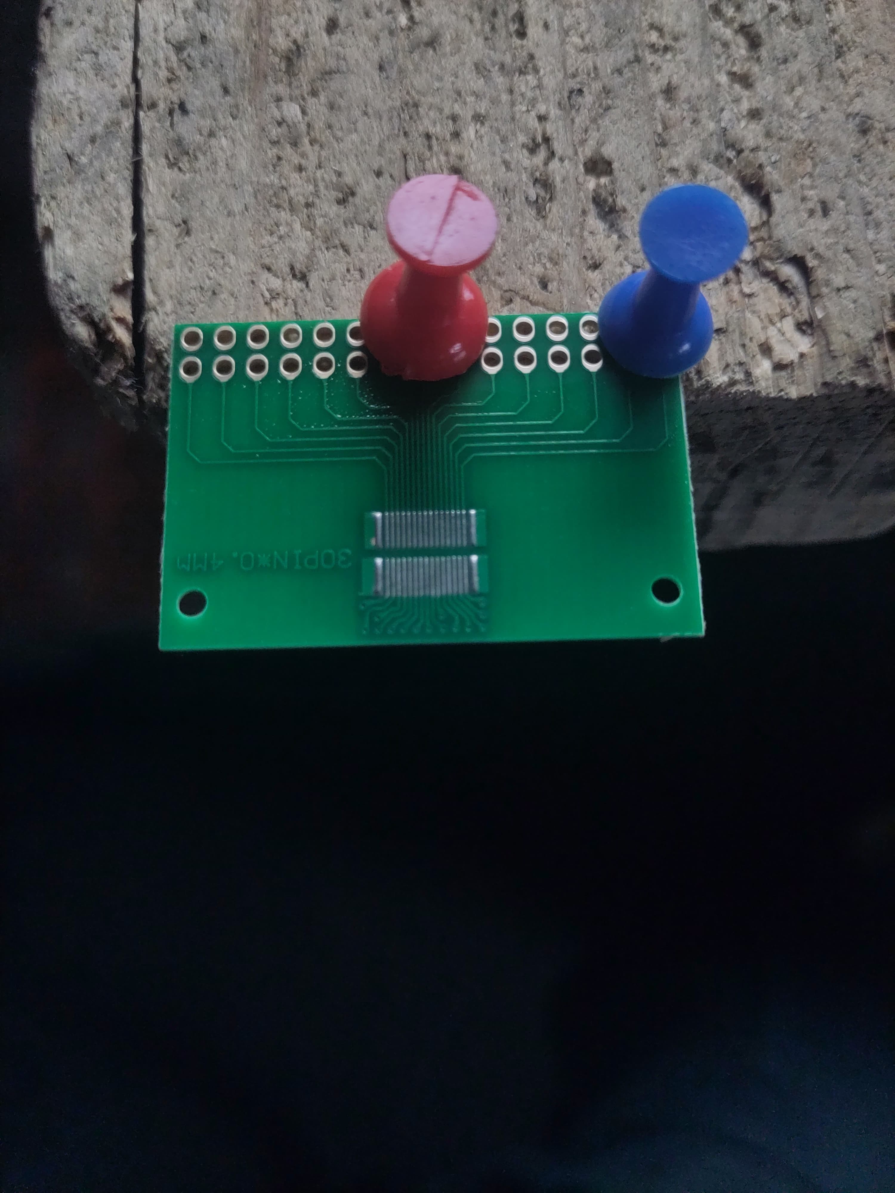
From Nokia’s schematic, I confirmed the keyboard runs on 3.3 V logic and has 3.3 V LEDs (verified via testing). I repurposed a double row 30 pin 0.4 pitch breakout board to route the FPC pins to a 2.54 mm header for prototyping.
I also identified the resistive touchscreen's 4-wire layout by resistance probing — no onboard controller, fully passive. Will drive it via an XPT2046 SPI controller.
The original LCD (LTJ035L001A) uses RGB input, but I’m currently adapting a Waveshare 3.2″ HDMI panel to fit the housing. The long-term plan is to build a custom HDMI driver board once I finalize display fit and power routing.
First attempt at 0.4 pitch pad tinning
 Salvaged and resoldered 20 pin FPC. No bridges on any of the FPC pins
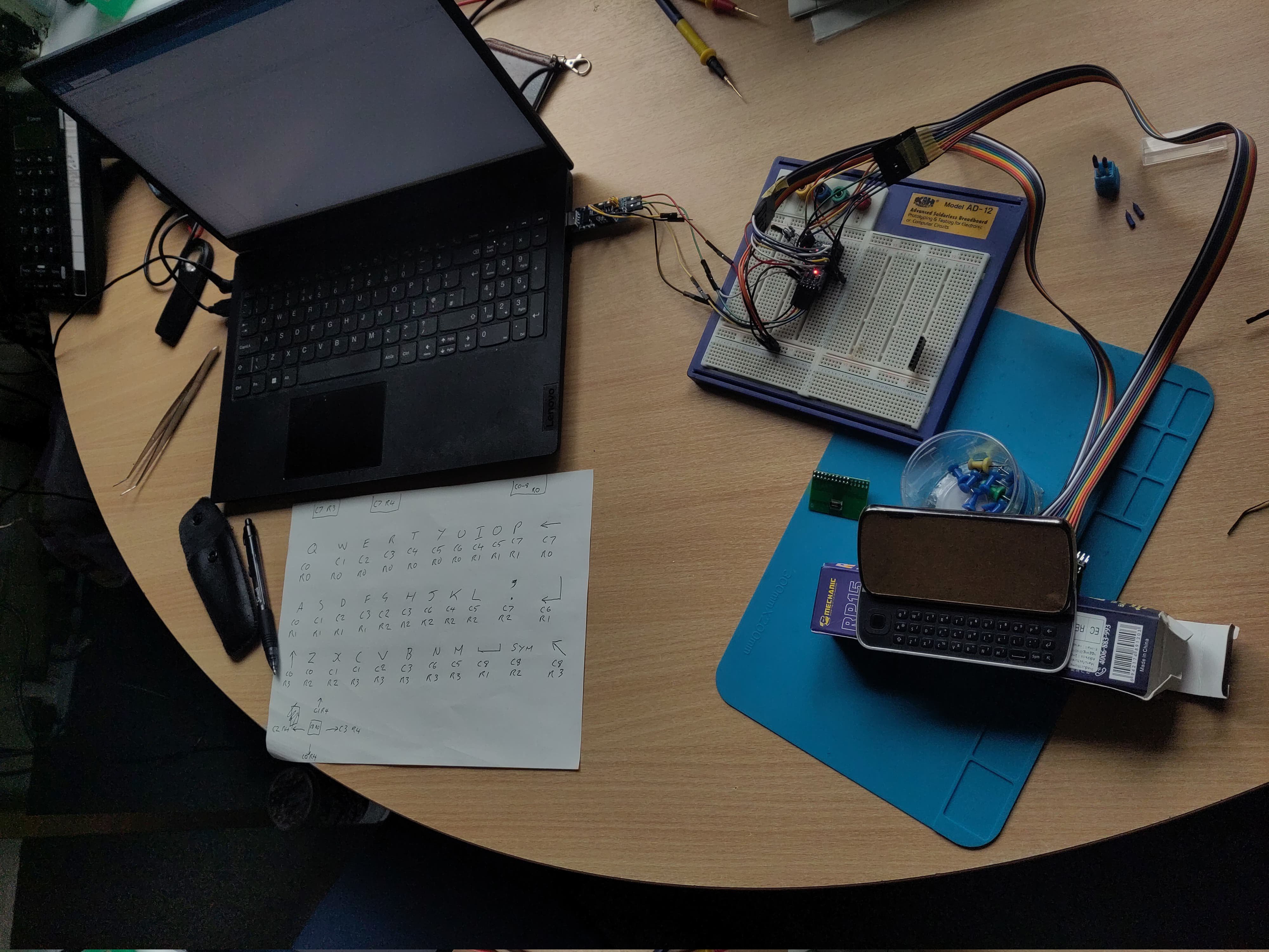
Keyboard mapping.
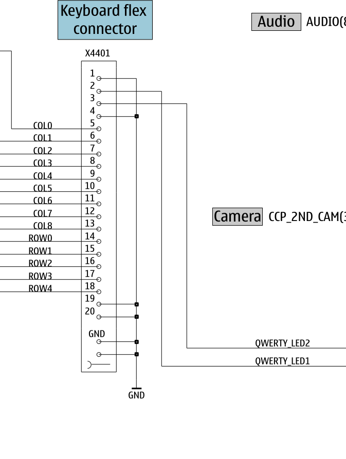
I’ve added an Excel spreadsheet to the Files section with the full keyboard matrix mapping — based on testing and confirmed against the Nokia schematic. This includes pin assignments, row/column layout, and working key labels
Discussions
Become a Hackaday.io Member
Create an account to leave a comment. Already have an account? Log In.