 retrobyte
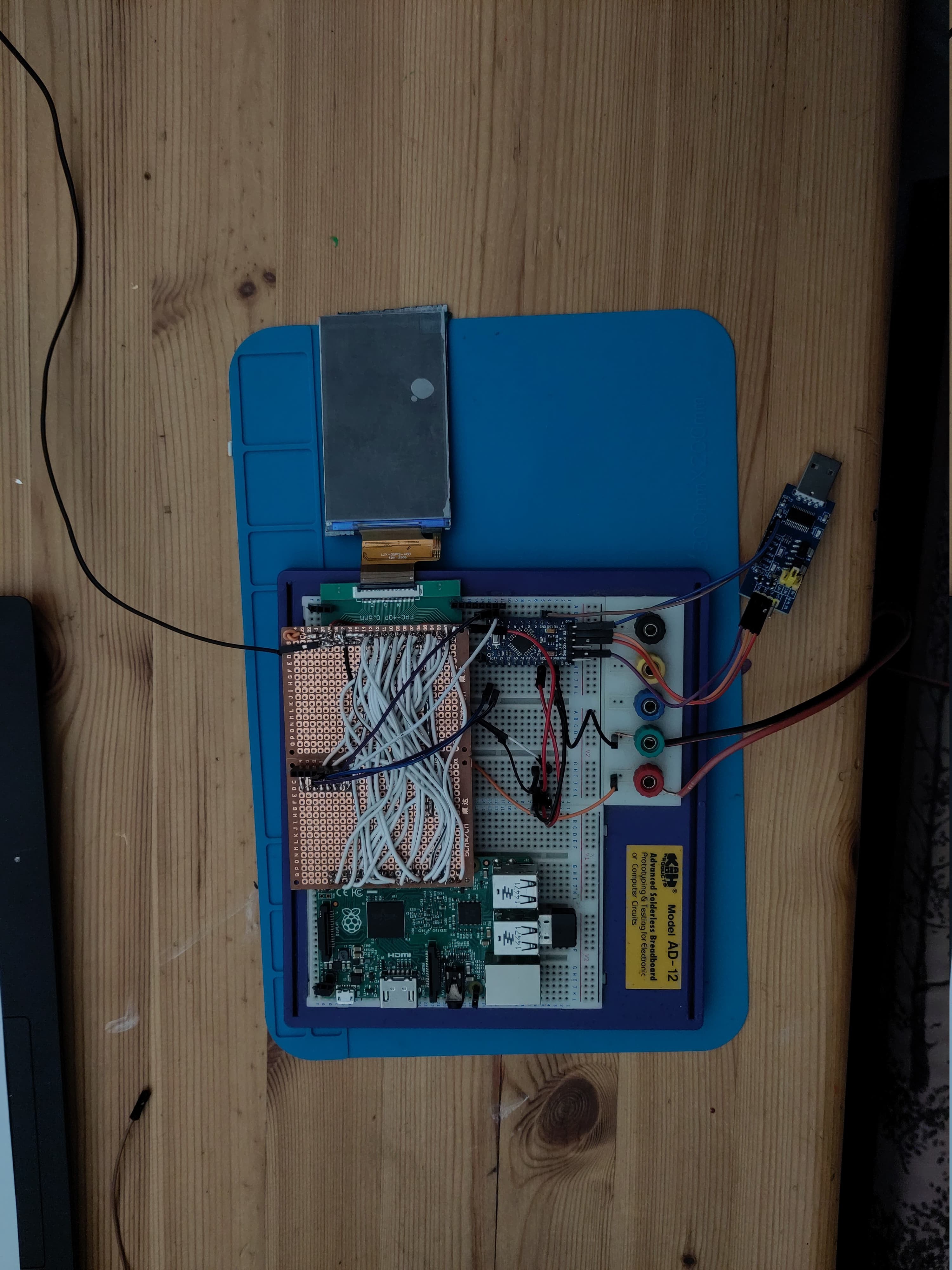
Spent some time this week building and refining the test rig for the LCD panel. The goal was to get the RGB565-compatible display hooked up and talking to the SBC to start validating the interface. Wiring was less messy than dupont cables and things were going smoothly — power was stable, backlight was on, and I had all the signals mapped out.
Unfortunately… no image yet — and before I could get much deeper into debugging, I accidentally dropped the LCD and cracked it. 💀
Not ideal, obviously. But I’m posting this as part of the "real build log" — mistakes and setbacks are part of the process. I’ve got a replacement screen already on order, and I’ll be taking a closer look at the signal integrity and timing once it arrives. This time, I’ll be securing the panel to the jig before powering on.
The upside:
-
The test rig layout itself works
-
GPIO/pin mapping seems solid
-
I now know exactly how fragile this panel is 😅
More soon once the new screen arrives. If anyone’s got tips on minimizing LCD signal noise or working with RGB565 over FPC, I’m all ears.
Discussions
Become a Hackaday.io Member
Create an account to leave a comment. Already have an account? Log In.