 electronicsworkshops
Introduction
A toggle switch with a timer using the 555 timer IC is an electronic circuit that allows a device to be turned ON or OFF alternately with each press of a button, while also incorporating a timing function to control how long the output remains active. By configuring the 555 timer in a bistable or monostable mode, the circuit can respond to user input to toggle the output state and include a delay or auto-off feature. This type of circuit is commonly used in applications like delayed lighting, timed relays, or simple automation systems where manual control with time-based operation is needed.
For Full Project:
https://electronicsworkshops.com/2025/03/26/toggle-switch-with-a-timer-using-the-555-timer-ic/

Bill Of Materials
| ID | Name | Designator | Footprint | Quantity |
|---|---|---|---|---|
| 1 | BC548B_C713615 | Q1,Q2 | TO-92-3_L4.9-W3.7-P1.27-L | 2 |
| 2 | NE555N_C510566 | U1 | DIP-8_L9.7-W6.4-P2.54-LS7.6-BL | 1 |
| 3 | JL301-50003U01 | U2 | CONN-TH_3P-P5.08_JL301-50003U01 | 1 |
| 4 | K4-6×6_TH | KEY1 | KEY-TH_4P-L6.0-W6.0-P4.50-LS6.5 | 1 |
| 5 | LED 3mm | LED1 | LED-TH_BD3.0_RED | 1 |
| 6 | 10nF | C2 | CAP-TH_L5.5-W3.5-P5.00-D1.2 | 1 |
| 7 | DB301V-5.0-2P-BU-P | U3 | CONN-TH_2P-P5.00_DB301V-5.0-2P-BU-P | 1 |
| 8 | 1N4007 | D1 | DO-41_BD2.4-L4.7-P8.70-D0.9-RD | 1 |
| 9 | 1uF | C1 | CAP-TH_L5.5-W3.5-P5.00-D1.2 | 1 |
| 10 | SRD-12VDC-SL-C | RELAY1 | RELAY-TH_SRD-XXVDC-XL-C | 1 |
| 11 | 1k | R1,R2,R3,R5,R6 | R_AXIAL-0.4 | 5 |
| 12 | 100 | R4 | R_AXIAL-0.4 | 1 |
provide.
Circuit Diagram

This circuit is a toggle switch with a timer using a 555 timer IC configured in monostable mode, designed to activate a relay for a fixed duration when a button is pressed. When the push-button is triggered, it sends a low pulse to the 555 timer’s trigger pin, causing the output (pin 3) to go high for a specific time determined by the resistor and capacitor connected to the timer (R3 and C3). This high output turns on an NPN transistor, which energizes the relay and can power an external device. An LED indicates the relay’s active state, and a flyback diode protects the transistor from voltage spikes. After the time period elapses, the timer automatically resets, turning off the relay and any connected load.
Section-by-Section Explanation
1. Power Supply Section
- VCC = 12V supplies the circuit.
- Decoupling capacitors are added (near the power rail) for stability and noise filtering.
2. NE555 Timer IC (U1)
- Operates in monostable mode.
- Pin 2 (Trigger) is connected to a push-button (KEY1), which pulls the trigger pin LOW when pressed.
- This initiates a one-shot pulse at pin 3 (Output).
3. Timing Components
- R3 and C3 set the timer duration: T=1.1×R3×C3T = 1.1 \times R3 \times C3T=1.1×R3×C3
- When KEY1 is pressed, the capacitor C3 charges and the output at pin 3 goes HIGH for a calculated time.
4. Output and Relay Control
- Q2 (2N3904 NPN transistor) acts as a relay driver.
- When pin 3 of the 555 is HIGH, it turns ON Q2, allowing current through the RELAY1 coil.
- A flyback diode (D2 – 1N4007) across the relay protects the transistor from voltage spikes.
5. Indicator LEDs
- LED1 (Green) shows relay status (ON when output is active).
- Connected with resistor R6 to limit current.
- LED2 at the output side shows power status or may be used for load indication.
6. Relay Output (J2)
- The relay’s Normally Open (NO) and Common (COM) terminals are connected to an output terminal block.
- This can switch external AC or DC loads like lamps, motors, etc.
Working Principle
- Initially, the circuit is OFF.
- When you press KEY1, pin 2 of the 555 is pulled LOW → triggers output HIGH.
- Pin 3 remains HIGH for a duration set by R3 and C3.
- During this time, Q2 turns ON → energizes the relay → turns ON external load.
- After the time expires, pin 3 goes LOW → relay turns OFF automatically.
PCB Files


3D files


Order Directly from PCB WAY
I have already uploaded all these required manufacturing files in PCBWAY website. You can easily go to the below link and place you order,...
Read more »
 Emmanuel Herrera
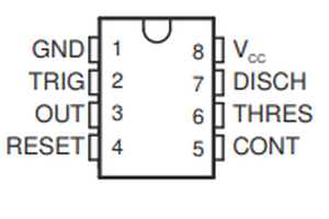
 EMRE
EMRE
 Melvin van Kalsbeek
 Tron9000