Close
0%
0%

No-Silicon digital clock

No-Si clock, with digital readout 0:00-11:59 TOTALLY WITHOUT SILICON. No microcontrollers, no chips, no transistors. Valves/tubes!

Public Chat
Similar projects worth following
The No-Si-Clock is ready! It is a digital clock with nixie tube readout in Valve/tube technology. I have used absolutely NO SILICON TRANSISTORS or chips, let alone a microcontroller. I have used 7 germanium diodes to keep the tube count acceptably low.

The 1Hz frequency is derived from the mains frequency (50/60Hz). Frequency division and counting the minutes and hours is done with dekatrons. Readout is nixie. In total I have used 31 tubes in this project, some vaccuum and some gas-filled.

I have done numerous clock projects in the past, some with nixie readout and some with other technology. I wanted to challenge myself and decided to go No-Si.

The objective of the No-Si-Clock is a digital clock with nixie tube readout in Valve/tube technology. I have used absolutely no silicon chips or transistors, let alone a microcontroller. I have used a few germanium diodes to keep the tube count acceptably low. The 1Hz frequency is derived from the mains frequency (50/60Hz). Frequency division is based on vacuum and gas-filled tubes. I am using 31 tubes in this project. 

The block diagram contains: 

  • Power supply block
  • One BPM generator block
  • Unit minutes block
  • Tens minutes block
  • Hours block 

This is now a finished, working project. The schematic diagram is available in the Files section (Kicad). Also the physical design of the aluminium base plate is avaible there (FreeCad). Check out the video below. 

I have done numerous clock projects in the past, some with nixie readout and some with other technology. I wanted to challenge myself and decided to go No-Si.

The design encompasses seven dekatrons, which are the counting elements. A dekatron is a neon-filled tube, with one anode and a great number of cathodes (typically 30), arranged in a circle. At any moment in time, a discharge is present at one of the cathodes and as long as nothing happens, the discharge continues on that cathode. This makes the dekatron a memory element. Ten of the cathodes represent a stable state, while the other 20 are transient. These 20 are connected together in two groups of 10 and by applying negative impulses to these groups, the neon discharge can be transferred from one to the next stable cathode. This makes the dekatron a counting element. The dekatron also has one of more outputs, each of which generates an impulse once per revolution.

One dekatron is used to divide the mains frequency by 5 and then by 10. This results in 1Hz.

There is another type of dekatron, that can count to 12 and can also be used to divide by 6.

Starting with 50 Hz (or 60 Hz) mains frequency, the dekatrons will do the following.

Dekatron type 6802 (or GS12C) divides by 5 (or 6) -> 10Hz

Dekatron type 6802 divides by 10 -> 1Hz... Hurraah!

Dekatron type 6802 divides by 10 -> one impulse per 10 seconds

Dekatron type GS12C divides by 6 -> one impulse per minute

Dekatron type GS10C divides by 10 -> drives the minute units and outputs an impulse per 10 minutes

Dekatron type GS12C divides by 6 -> drives the 10 minutes and outputs an impulse per hour

Dekatron type GS12C divides by 12 -> drives the hours

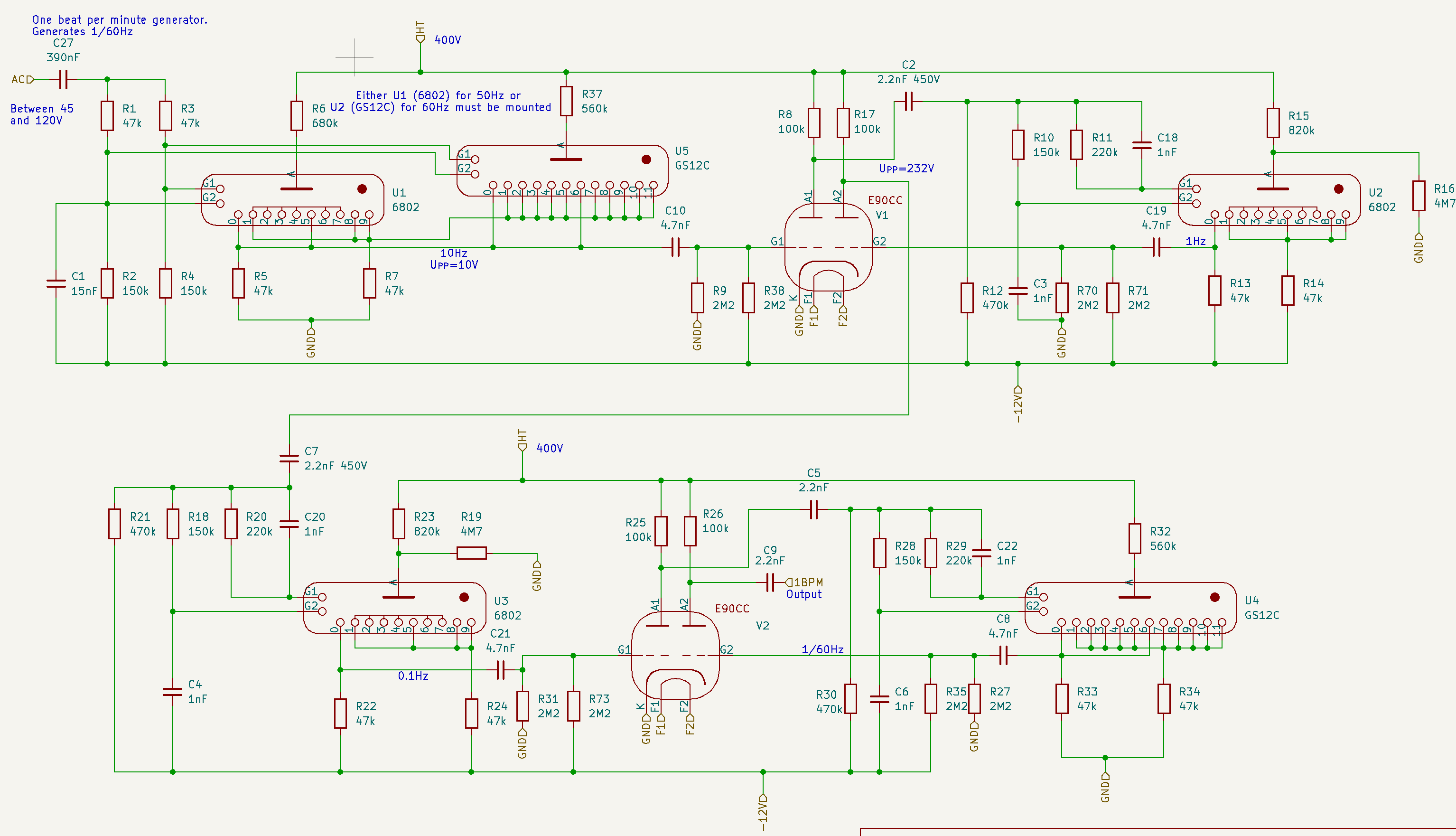
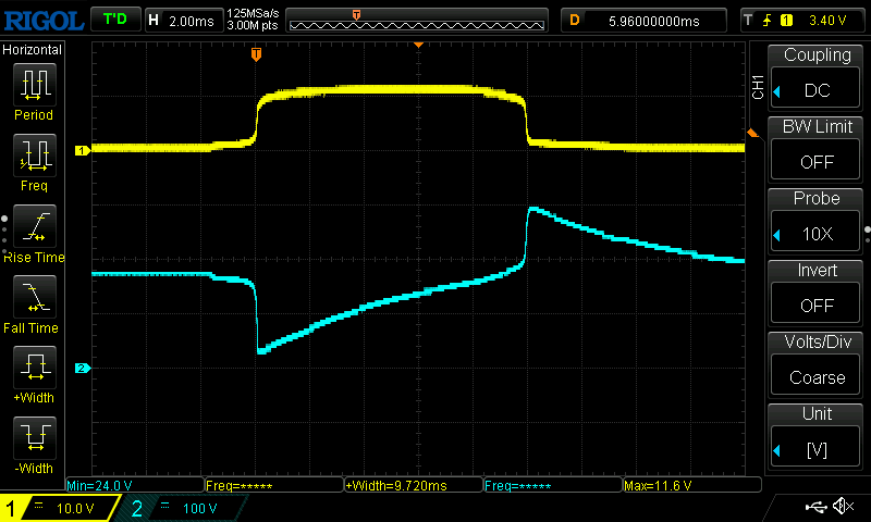
Fig. 1. The "one beat per minute generator". Mains frequency 50Hz is divided by 5, 10, 10 and 6.

The first stage divides the mains frequency (50 or 60Hz) by 5 (or 6). In principle, this is just a 'dekatron spinner' circuit, like the ones that can be found on the internet. But the difference is that the output impuls from 2 of the dekatron's cathodes is taken, amplified and inverted by one of the triodes in a E90CC double triode. For each rotation of the spinner, two such impulses are generated (10Hz) and fed to the second stage, which divides the frequency by 10, which gives a one Hertz (1 Hz) impulse.

The stages that drive the nixies, pose an extra problem. The outputs of the dekatron are not suitable to drive the nixies just like that. The signals need to be amplified and inverted. This will be handled by the E90CC's. These double triodes were specifically designed back in the day for computer and other digital purposes. They are unsuitable for audio applications, among others because the suffer from microphony, and that's very nice because that keeps the price down. I was able to lay my hands on the required number of E90CC's for €2 each.

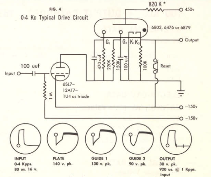
Fig. 2. Driving a nixie tube from a dekatron requires 10 triodes.

If you study figures 1 and 2 carefully, you will notice that the coupling between the stages is done using a 2.2nF capacitor. This is to decouple the high anode voltage from the rest of the circuit. This leads to short impulses. This is typical of digital tube...

Read more »

20250802_120236.mp4

Video showing the completed and working end product

MPEG-4 Video - 25.64 MB - 08/02/2025 at 14:25

Download

No-Si-Digital-Clock.zip

KiCad schematic files, updated at end of project

x-zip-compressed - 148.68 kB - 08/02/2025 at 14:24

Download

20250727_164507.mp4

Another milestone: the units seconds section is working. 1Hz is given to the third dekatron, which makes one step per second and takes ten seconds for a full rotation. This dekatron is a GS10C, a type with all 10 outputs available. Each output is connected to a triode to invert the signal and drive one nixie figure. It takes 5 E90CCs to drive one nixie tube. This is a temporary set-up; because I have only 4 nixie tubes, there will be no seconds in the end solution. On the other hand, it might be a useful feature for setting the time.

MPEG-4 Video - 25.39 MB - 07/27/2025 at 14:58

Download

20250726_161645.mp4

Major milestone: I have the 1 Hz working. Mains frequency is given to the rightmost dekatron, which spins with 50 steps per seond, that gives 5 full rotations per second. The outputs from states 0 and 5 are taken, inverted by an E90CC triode. This gives a 10Hz pulse train, which is given to the second dekatron, which makes 10 steps per second and therefore one full rotation in a second.

MPEG-4 Video - 10.87 MB - 07/26/2025 at 14:37

Download

No-Si-Clock.FCStd

This is the FreeCad 1.0 file containing the design of the aluminium front plate with drill holes for the tubes and screws

x-zip-compressed - 108.33 kB - 07/26/2025 at 14:35

Download

  • 3 × 6802 dekatron
  • 3 × GS12C dekatron
  • 1 × GS10C dekatron
  • 3 × PY88 rectifier tube
  • 16 × E90CC double triode

View all 23 components

  • Problem remaining to be solved

    Charles van Den10/20/2025 at 19:43 0 comments

    I noticed that the dekatron that is counting the tens of minutes sometimes seems to miss a step. It seems to be geting worse when the clock is left on for a longer period of time (several hours). I guess I will have to look into that. I remember that this particular tube has shown some problems before, when I was building. Because it appeared to have a problem in a certain step, I decided back then to have it run in the opposite direction, e.g. counterclockwise in stead of clockwise. Which is kind of strange for a clock, admittedly. But it is as easy as swapping the G1 and G2 connections. 

    I have already tried to change the triode that is driving it, but that doesn't solve the problem. So the problem is either in the resistors and capacitors generating the phase shift G1/G2, or it is in the GS12C itself. I still have one or two of these lying around, but still it is a lot of work, because this particular tube does not sit in a socket, but the wires are soldered straight on. Maybe it's best to start with some measurements of the G1/G2 waveforms and then some tweaking.

  • Bug

    Charles van Den08/14/2025 at 08:45 0 comments

    Yesterday, I noticed a problem with the No-Si digital clock. The hours figure show something unreadable. On closer inspection, it looked like the '5' was always burning regardless the actual hour, through the intended figure. I thought a possible cause might be the triode tube, so I exchanged the responsible E90CC with another one in the clock. Bingo, now the '3' was constantly burning. So yes, the tube was the cause. Luckily, I have some spares laying around, so I put in another E90CC and the problem was solved.

  • How it began

    Charles van Den08/05/2025 at 16:08 0 comments

    Flash back to a few years ago.

    I have been experimenting and building circuits with dektrons for years now. Absolute highlight was a project I did for Elektor, the printed magazine in 5 languages. The original title of this was: I finally found a useful application for dekatrons. It was published in 2022 under the title Audio Spectrum Analyzer With Dekatrons. Which is exactly what it is: it uses 7 dekatrons to display the levels of audio in the different frequency. Stereo, also. You can still read this story at https://www.elektormagazine.nl/labs/i-finally-found-a-useful-application-for-dekatrons

    In 2023, to get inspiration I visited the WITCH computer in the National Museum of Computing, near Bletchley Park, which is comprised of hundreds of dekatrons. The people working there have managed to get the machine running, which I think is an incredible feat. They do a daily demonstration.

    In July 2024, I got the opportunity to buy a couple of 12 step dekatrons (GS12C), about which I didn't hesitate a second. I had no clue what I was going to use these for, but I knew I needed them urgently. They had been laying around for a couple of months until the idea to use them in a digital clock gradually matured. 

    In my previous projects, I had been using dekatrons only as display devices. I did not use them for their original purpose: as counting (up/down) device. That was because all the "counting" was done in a microcontroller and the microcontroller directed the dekatron. This bothered me for a while. I wanted to do something where the dekatron was used for its original purpose, to count things and not be subordinate to a microcontroller.

    I did some experimenting on how to couple the 'carry' on the output of one dekatron to the input of the next dekatron. Two document showed how to do this: the Sylvania brochure Decade Counter Tubes second edition and the Ericsson book Electronic Counting Circuits by J.B. Dance (chapter 4). but of course, the circuits were intended for different types of dekatrons, for different types of triodes and for different supply voltages then I intended to use. So I had to do a lot of experiments before I got it right. Luckily, the documents described very well the intended time-shifted waveforms on the two guide electrodes G1 and G2. So I could measure the waveforms on the oscilloscope and choose component values that gave the intended waveforms.

    I took the idea from Sylvania to connect G1 through resistor-and-capacitor-parallel and G2 through an RC-filter-network, as illustrated below.

    In the Ericsson document, they use a different RC topology, e.g.:

    I found out that dc coupling the cathode of a dekatron to the grid of the triode means that the triode is conducting for a longer duration, which means that the power consumption is relatively large. This also leads to the necessity of a high-watt anode resistor. This can all be avoided by introducing a small capacitor between dekatron-cathode and triode-grid, which has the effect that only a brief pulse is given to the triode.But this technique cannot be applied for driving the nixies. So in the end I used both AC-coupling and DC coupling.

    In chapter 4.4.9 of the Ericsson document, it is described how to drive nixie tubes (Ericsson calls them Digitrons) from a dekatron. Unfortunatly, the use a GCA10G type of dekatron for this puropose, which has 10 auxiliary anodes, that can be directly tied to the figures of the nixie tube. So I had to design a way to solve this for a normal dekatron. That proved to be quite easy, it only requires a lot of triodes: 10 triodes for one digit. 

    I found out the existence of the E90CC double triode tube, a tube specially intended for digital purposes. Fun fact about the E90CC that it clearly states in the datasheet that this tube is 100% useless for audio applications, because of microphony and hum. I really like this, because it means that not all of them have been taken by the audiophiles.  I...

    Read more »

  • Family

    Charles van Den08/05/2025 at 12:44 0 comments

    Presented the No-Si Digital Clock to the members of the family. Wife and kids (age 20+) were quite amused, I think they even liked it. My son wanted to know exactly the rotation time of each dekatron. 

    The clock is standing in the living room next to the tv now. We'll see how annoying the continuosly spinning dektrons are when viewing tv. Especially the very first one, rotating five times per second.

    I think I will leave it there for a week or so and then it'll go into storage. Just to get it out sometimes to impress friends and family.

  • Ready!

    Charles van Den08/02/2025 at 12:57 0 comments

    The No-Silicon Digital clock is ready! It is working correctly now. You can set the minutes by turning the "time adjust" knob counterclockwise and adjust the hours by turning it clockwise.

    It consumes a little over 80W (mainly consumed by the filaments) and keeps the room nice and warm.

  • Tube less

    Charles van Den08/01/2025 at 14:16 0 comments

    No, not tubeless, just one tube less... 

    The filaments of the rectifier tubes and triodes consume a lot of power. In total, 70W. In my transformer drawer I found a big transformer, with secondary taps of 23V, 24V and 25V. Therefore, I decided to work with strings of 4 tubes in series. Being all E-series tubes, 4 x 6,3V = 25.2V would fit well enough with the 25V output of the transformer. So, 4 strings of 4 E90CC's and one string of 4 EY88's. Although I needed only 3 EY88's in my design, I added one extra, doing nothing, just hanging around in the corner as a dropper tube. 

    While gradually realizing the No-Si Clock, I realized that I would need some kind of mechanism to set the time initially. I came up with a switch with three positions: one normal position, one position in which the minutes tick switfly by and one position in which the hours pass by. But where am I going to put the switch? then I remembered the useless extra EY88. If I could do without that tube, I would have a place to put the switch. The solution I ended up with is to use not EY88's, but PY88's. These were used in series configuration, directly connected to mains voltage in tv sets of the day. They officially require 26V filament voltage each, so instead of stringing them in series, I could just use 3 of those, connected in parallel to the transformer's 25V. They will also work on a volt less.

    Now I have room for my switch and additional advantage: the power consumption drops by almost 10W (6,.3V×1.55A).

    Photo: The time adjust knob sits where a useless EY88 used to sit. You can see remaining three PY88 rectifier diodes. The switch on the far right may be the one I am going to use.

  • Rotating left

    Charles van Den07/28/2025 at 15:04 0 comments

    I was working on the part of the circuit that deals with the tens of minutes. I had the dekatron wired up. Every time it gets an impulse, it should jumps to the next stage. I have used a GS12C, which has 12 stages. I have connected stage 6 to stage 0, stage 7 to stage 1, etc, thereby halving the number of outputs to 6, which is good, because it's the tens of minutes and after 5 it is supposed to go back to 0. So we will count 58, 59, 00, 01...

    The particular problem I had is that the dekatron stepped through the stages, but got stuck on 0. It would not move from 0 to 1. I checked all solder joints, resistors etc. but didn't find a problem. The dekatron's inputs are two guides, G1 and G2, which are supposed to get an impulse, briefly shifted in time after one another. If you give an impulse to G1 and then to G2, it moves one stage up. You can also reverse the effect, by giving an impulse first to guide G2 and the to G1, which will cause the dekatron to move one stage down. 

    As an experiment, I reversed G1 an G2 and the dekatron started to move in the reverse direction and - a little to my surprise - did not get stuck anywhere. So for now, I think I will leave it this way. I have not connected the nixie tube yet; in this case I consider it an advantage, because I will have to reverse the nixie wiring to compensate for the reverse dekatron.

    It looks a little like cogwheels now, like in a mechanical clock. Instead of looking at this as a problem, I might see this as a feature. I'll have to reverse some of the other dekatrons also, I guess.

  • The 1 Hz Milestone

    Charles van Den07/26/2025 at 14:39 0 comments

    Major milestone: I've got the 1 Hz working. Mains frequency is given to the rightmost dekatron, which spins with 50 steps per seond, that gives 5 full rotations per second. The outputs from states '0' and '5' are taken, inverted by an E90CC triode. This gives a 10Hz pulse train, which is given to the second dekatron, which makes 10 steps per second and therefore one full rotation in a second. See the attached movie in the files section.

  • Spinning

    Charles van Den07/24/2025 at 20:28 0 comments

    Mixed day. After I blew up my function generator two weeks ago, by applying 300V to its output, today the magic smoke escaped for no reason from my 450V home built power supply. My indestructible 300V Delta Zierikzee power supply unfortunately just doesn't give enough for the Dekatrons to fire up. thankfully I found yet another home grown power supply in the attic, up to 400V.

    This helped me to find one problem why the Dekatron wasn't spinning on first try. It appeared that for some reason, a large DC component appeared on the gates of the dekatron, where I would expect only 50 ~ 100V AC, phase shifted between G1 and G2. I still haven't pinpointed the cause, but I solved the problem by adding a 390nF capacitor, blocking whatever DC component there is.

    Had it working. Then it stopped working again. This turned out to be a loose solder joint with one of the pins of the dekatron. With that solved, I have a spinner. Next stage is to get the output signal from the spinng dekatron. That should be 10Hz, to be inverted by one of the triodes and fed to the second dekatron, which should churn out the desirable 1Hz.

  • Woodwork and soldering

    Charles van Den07/23/2025 at 19:00 0 comments

    Yesterday and today I worked on a wooden base plate, to put everything on including the heavy transformers. I glued three pieces of wood together, cut it and painted it. The aluminium base plate will sit on the wood using a hinge mechanism, so that it is easy to inspect the back where all the soldering should take place.

    I soldered the rectifier circuit with EY88's. so I now have something like 200V and 400V. The EY's and all other tubes that a filament voltage of 6.3V will be connected in chains of 4, connected to 25.2V. Or something in that neighbourhood. 

    I preliminaruly connected the nixie tubes so that display something (it's currently 12:06 all day). I started wiring the first dekatron circuit. It gives a sign of life but it isn't spinning yet.

View all 13 project logs

  • 1
    Before you begin

    If you want to reproduce this project, that's great! But before you begin, beware of a few things.

    This projects involves voltages up to 400V DC!

    If you are afraid of high voltages or not used to working with it, don't do this project. It is a little bit dangerous. I accept no responsibility for any accidents that occur from attempting to reproduce (parts of) this project or otherwise. Do anything at your own risk.

    It is quite a difficult build. If you have no experience with tubes/valves, forget it.

    You will need a digital oscilloscope with at least two channels. I advise against an analog scope, because some of the signals are not repetitive.

    This clock is a show piece, a conversation starter, something to boast and/or brag about, a novelty or whatever you name it, but it is not something to turn on 24×7! It consumes 80W, heats up your room and the tubes have a life expectancy of a little more than one year.

    Do not let children and/or adults get near. There's high voltages everywhere, the thing gets hot, it's heavy and fragile.

    The design depends on the mains frequency. Mine is built for 50Hz. If your mains frequency happens to be 60Hz, don't worry. You just replace U1 (6802) by U5 (GS12C) and the first stage will not divide by 5, but divide by 6. Problem solved. This does mean you need one extra GS12C instead of a 6802, though.

    I built this project without a pcb, in the old style of tube technology with so-called point to point wiring. I regret this decision. Point to point wiring is soo laborious, tedious, error prone and what not. So if you have the chance, design a pcb!

    Dekatrons with 10 steps, like the 6802 are not hard to find, in my opinion. But:

    The 6802 has not all of its 10 cathodes wired to separate pins on the base. The cathodes 1, 2, 3, 4, 6 and 7 are tied together. This is OK for in the 1BPM generator (the prescaler that converts 50Hz into 1/60Hz). But this makes the 6802 unsuitable in the unit-minutes section, because we need all cathodes wired to seperate pins in order to drive the nixie. This is why I chose the GS10C for the unit-minutes. I happened to have only one of those and more 6802's, so that is why 6802 are still in the circuit.

    I use GS12C's in three places. This is a dekatron that counts to 12 and has all cathodes individually exposed. I guess this thing is hard to get. I was just lucky to find a handful of these on the local marketplace a few months ago. They have no socket, they have lugs that you can solder directly to. A suitabel alternative is the CV1740 or GS12D, but I'm afraid these are also made of unobtainium.

    An alternative would be to use normal 10-step dekatrons and then design a reset mechanism, so that it jumps back to 0 after hitting the 6. That is feasible. You will end up with more tubes and I guess more is betterer.

    The E90CC double triodes on the other hand are easily obtainable and dirt cheap (I bought a lot at €2 each). Why? The E90CC was designed "for use in computer circuits" and is perfectly unsuitable for audio applications because, as the datasheet clearly indicates: the E90CC is "not intended to be used in circuits critical as to hum, microphony or noise".  One cannot thank the engineers at Philips too much for these built-in features!

    About the transformers. I found a suitable 25V 100VA transformer in my junk bin. There are two additional transformers needed: a small 9V transformer for the -12V line and a 2x110V transformer for the 200V and 400V DC lines. If you can't find these, nowadays you can have a transformer custom built on aliexpress for next to nothing.

  • 2
    Build step by step

    Think about your mechanical construction first. I mounted all the tube sockets in an aluminium base plate and put all the other components and wiring under the hood. I devised a hinge mechanism using a metal rod from an old ink jet printer to make the hood easily opening, to be able to work on the internals. As already said, next time I would make a pcb, for point to point wiring is terrible.

    Build the power supply section first. In the beginning, the load is still low, so as it is an unregulated power supply, all voltages will be a little bit on the high side. I used a variac to compensate for this. It is important that the V-HT is always exactly 400V (+/-5V). Measure this voltage regularly and correct if necessary. I inserted R74 (1k5) on sheet 'power supply' to bring down the V-HT a little bit. You may have to tune R74. The -12V can deviate a little bit, but not too much. The nixie voltage (200V) isn't that critical.

    When you have the power supply running, the next thing to do is make the 'spinner' U1/U5 work. This dekatron makes five full circles every second. States 0 and 5 generate a 10Hz positive going impulse train that goes to gate 1 of double triode E90CC V1 . You will need an oscilloscope to verify that the Vpp equals about 10V. Also verify that on the anode 1 of V1, there is a similar pulse train, but negative going and with a much higher Vpp (>100V). See figure below. Yellow is pin 0 of the dekatron, blue is the anode of the triode.

  • 3
    Pulse filter

    Build the circuit around R10/R11/C18/C3, connect to G1/G2 and check the results. Both should give a negative going pulse, but one shifted in time a few millisconds with respect to the other. This is what makes a dekatron step to the next stage. See here an oscilloscope view of these pulses.

    Yellow is G1 and blue is G2. Both are negative-going pulses of 40V or more. First, G1 is the most negative. After 100μs or so, G2 is the most negative. This causes the dekatron to take a step.

    These circuits are repeated with slight variations, with each stage of the clock. However, while the first four dekatrons are AC-coupled (through a 4.7nF capacitor) from their cathodes to the grid of the triode, the remaining three are DC-coupled. This is required, because the triodes V5 etc. drive nixie tubes. Without DC-coupling, the nixie would only light up for less than a millisecond.

    Ouch, I spot an error in the circuit diagram. R43 should not be connected to HT (400V) but only to UNIXIE (200V). Otherwise, the germanium diode D1 will not survive! Same as R60, which is drawn correctly.

View all 3 instructions

Enjoy this project?

Share

Discussions

Isaac Wingfield wrote 08/03/2025 at 02:56 point

"No silicon"?? What about the tube envelopes?

  Are you sure? yes | no

Charles van Den wrote 08/05/2025 at 12:46 point

You are absolutely right! I'll have to withdraw the whole project ;-)

  Are you sure? yes | no

Charles van Den wrote 07/12/2025 at 18:46 point

Thank you. I have done more dekatron projects, check out this project: https://www.elektormagazine.nl/labs/i-finally-found-a-useful-application-for-dekatrons which was actually printed in the Elektor Magazine. Stereo audio spectrum analyzer.

  Are you sure? yes | no

Ken Yap wrote 07/08/2025 at 08:13 point

Wow, the last time I saw dekatrons was in a lab event counter some 50 years ago. Cool project. 👍

  Are you sure? yes | no

Similar Projects

Does this project spark your interest?

Become a member to follow this project and never miss any updates