 Tim S
Tim SThe software has seen a few improvements since the previous project log, and there have been some hardware changes.
To start with the latter, I've switched from the ESP32 WROOM devkit I was using previously to a Seeed XIAO ESP32 S3. This was mostly to save space, once I realized I wouldn't need more pins than were already available on the XIAO. I had originally planned on switching to a Seeed XIAO ESP32 C3, before realizing the C3 doesn't have the PCNT support for the rotary encoder. Rather than switching to a software solution for the encoder, I just grabbed the S3 instead.
I have also replaced the single RGB LED with a NeoPixel Ring from Adafruit. My daughter had complained once or twice about not knowing how much longer she needed to stay in her room. The ring can be set up to light up only some of its LEDs to indicate remaining time in a visual way.

The software has seens some upgrades as well. The dial can now be used to adjust the brightness of the display and LED ring, start a nap, and lock the display. The switch has to be held for 3s to unlock it again. This is all the functionality I had intended to include for local control, at least for the MVP, so I think the software changes will slow down for a bit now. I have started work on designing a PCB in KiCad, and building PoC for it on perf-board. I've also started working on a design for the case.
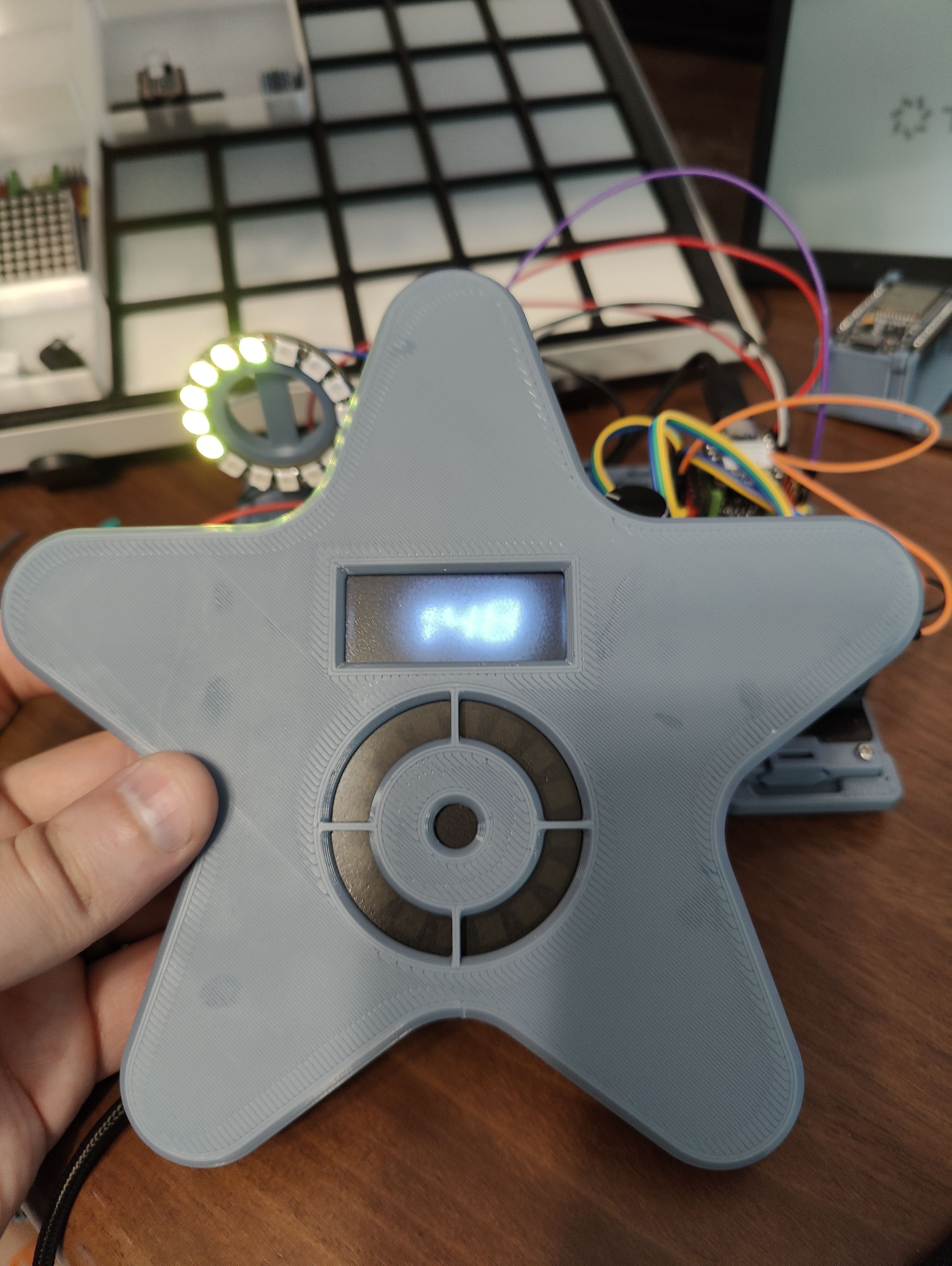
The thought is that the face/control panel will be 3d printable separate from the rest of the case, and connect to the main PCB via a few JST-XH connectors. That way, different designs just have to have a sufficiently large flat surface, and some alignment pins/screw holes to attach it. The PCB will likely also just attach with some small metric bolts, so the case would also need some embedded nuts, heatset inserts, or other threaded holes for it to attach to. The panel slot will, at least on my case, I think be designed to have space for a semi-transparent acrylic sheet to act as a bit of a diffuser/dimmer layer.
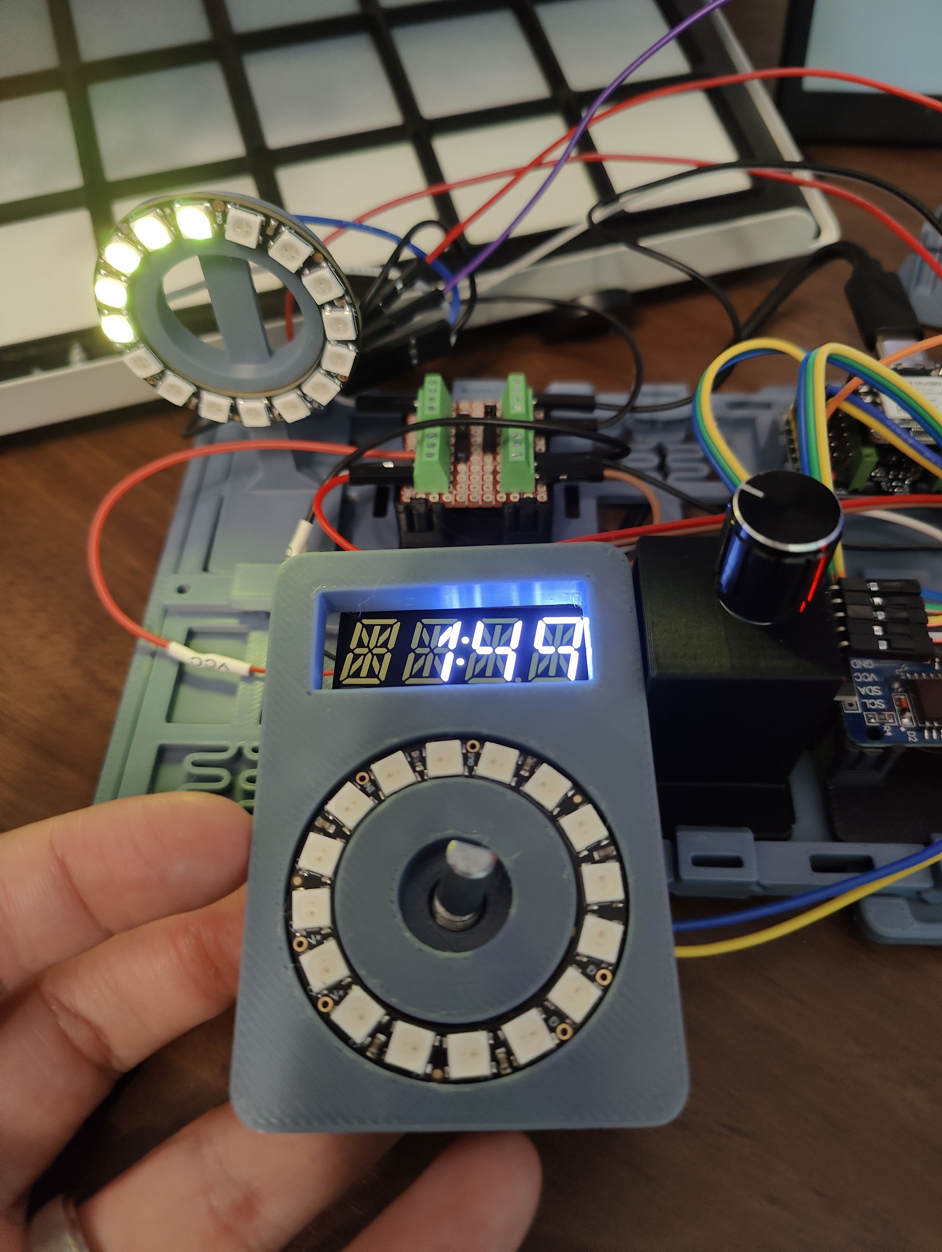
I'm also experimenting a bit with removing the battery holder from the RTC module I've got, and instead connecting it to the module via some wires, so it can be placed somewhere more accessible (E.G. to have a battery cover somewhere on the case, so the battery can be swapped without completely opening it.)
Discussions
Become a Hackaday.io Member
Create an account to leave a comment. Already have an account? Log In.