 Tim S
Tim SLots of progress since the last update. I designed a case and a custom PCB, made a couple dumb mistakes, and fixed most of them (albeit in a slightly bodgey way).
Custom PCBs from PCBWay
First thing I did after the last update was work on a schematic and PCB design. I put the schematic together in KiCad; mostly just breaking pins out into connectors for the various other components, but also a transistor to use as a logic level converter (remember that dumb mistake thing?). PCBWay was kind enough to reach out and offer to supply the PCBs for this project for free.
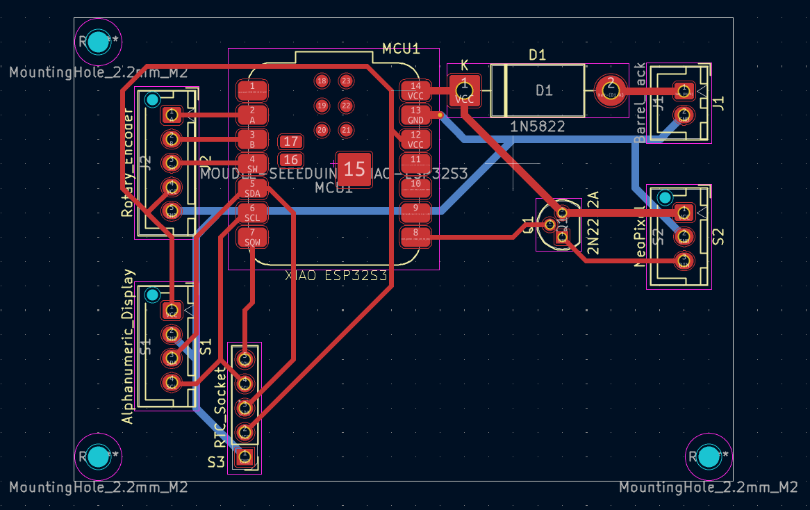
The process was super quick and easy; with the design complete, I just exported the gerber files and uploaded them to PCBWay. This is a fairly basic 2-layer PCB, but the options available on their site have me excited to try projects that would justify something more complex. A couple weeks later, the PCBs arrived and I did some quick testing to make sure they were working as expected - all perfect, thanks PCBWay! I look forward to continuing to work with them in the future on this and other projects.
Initial Assembly
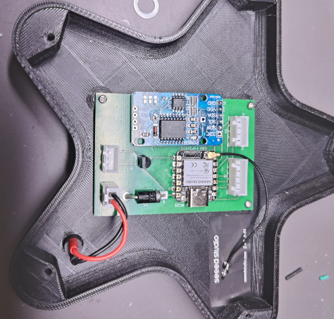
The testing done, I soldered the components onto one of them.
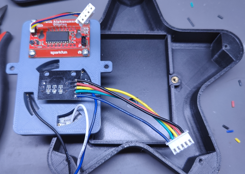
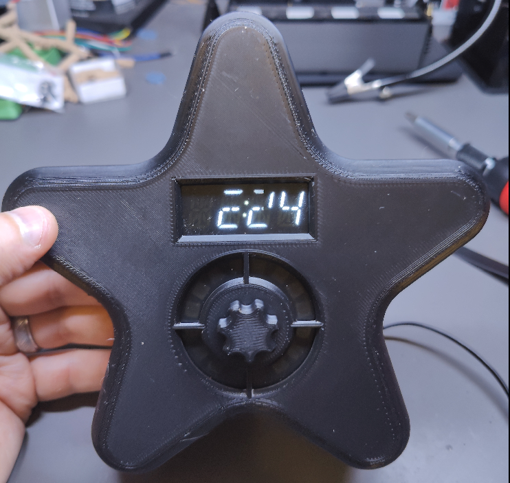
The front of the case was completed as well; I used a weird mix of heatset inserts of various sizes, and some manually threaded holes. This was done mostly so I could experiment and see what process I liked best, and for V2 I’m hoping to standardize onto a single method/piece, to simplify assembly. The diffuser is a small piece of translucent gray acrylic that I drilled a hole in and sprayed with a satin varnish to make a little more opaque.
Debugging and Re-Assembly
With everything assembled… nothing worked. According to some serial debugging, the I2C addresses I was expecting to find the display and RTC at were missing, and nothing I did could get the LED ring to light up. The I2C issue ended up being a loose connection, which was fortunately quite easy to resolve. The LED Ring… that was from me trying to cheap out and use a single transistor like a logic-level converter. I’m looking into a better way to do it in the future, but for the time being, I just manually wired in a 4ch logic-level converter I had on hand. A bit wasted here, but it works.
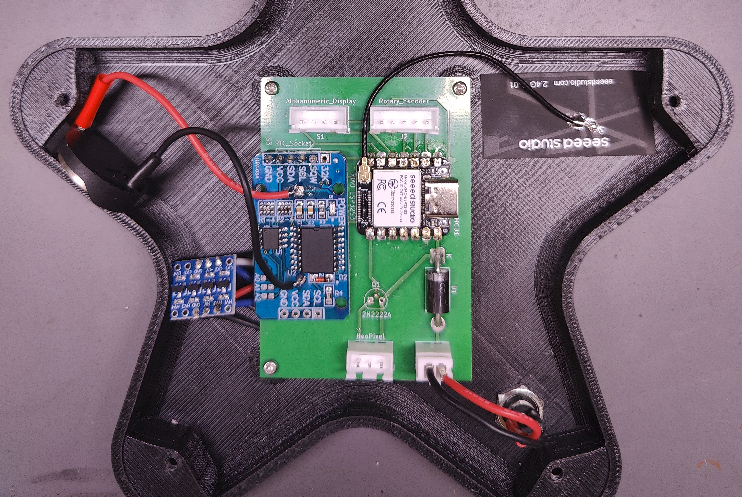
After that it was just a matter of reassembly… and then discovering that I’d broken the square-wave interrupt from the RTC somehow. Honestly, after checking the connections with a multimeter and watching both the I2C and SQW signals with a logic analyzer, I’m not sure what I did. But I appear to have burned it out somehow. Fortunately, the rest of the RTC is working just fine, so for now I’ve just switched the code over to poll roughly every 1s based on the internal clock instead of more exactly every 1s based on the SQW output.
It's Alive!
My daughter has been using it for a few nights now, and loves it. She’s excited about getting to paint it soon, once I have time to disassemble it long enough to do so, and likes knowing when it’s “almost time.”
Next big step is adding the bluetooth functionality, so I can check and adjust the schedule and start/stop naps without having to go into her room to do it. But given my limited experience with mobile development I expect that to take a fair while.
Discussions
Become a Hackaday.io Member
Create an account to leave a comment. Already have an account? Log In.